|
|
D01399820D |

Microphone Adapter
REFERENCE MANUAL
.jpg)
|
|
D01399820D |
Microphone Adapter
REFERENCE MANUAL
Thank you very much for purchasing a TASCAM CA-XLR2d Microphone Adapter.
Before using this unit, read this Reference Manual carefully so that you will be able to use it correctly and enjoy working with it for many years. After you have finished reading this manual, please keep it in a safe place for future reference.
You can download the Reference Manual from the TASCAM website.
|
|
CA-XLR2d |
 Mic adapter to add XLR inputs to mirrorless cameras
2 XLR/TRS input jacks enable optimal mic selection for different filming situations
Built-in high-performance AD converters enable direct transmission of digital audio to cameras through compatible accessory shoes without degradation (using compatible models from Cannon, Fujifilm and Nikon)
Power can be provided by cameras through compatible accessory shoes (using compatible models from Cannon, Fujifilm and Nikon)
Built-in high-performance HDDA mic preamps on the XLR/TRS inputs enable high audio quality, low noise and a wide dynamic range (mic/line level switchable, +48V phantom power supported)
3.5mm stereo mini jack supports plug-in power, enabling connection of gun mics, lapel mics and wireless mics, for example
Connection to numerous mics with analog inputs enabled by included battery box, cold shoe mount adapter and mic holder with shock mount structure to control vibration noise
Cold shoe on top enables attachment of mics, wireless receivers and other devices that support shoe connection
Analog output jacks support two modes
 Camera mode (
 .jpg) ) enables audio transfer to camera mic inputs
) enables audio transfer to camera mic inputs
Headphone mode ( .jpg) ) enables direct monitoring using headphones
) enables direct monitoring using headphones
The same unit can be used with compatible cameras from Canon, Fujifilm and Nikon by using optional CA-AK1-C, CA-AK1-F and CA-AK1-N accessories shoe connection adapters (sold separately)
Attenuation function (0 dB/20 dB/46 dB)
Low cut filter function (OFF/80 Hz/220 Hz)
Limiter function
Auto level function adjusts recording levels automatically
Indicators that show level overloads for each channel
1+2 LINK function links VOLUME, LEVEL and LIMITER operation of INPUT 1 and INPUT 2 when using a stereo mic, for example
Cable holder useful for managing cables around the camera
Conventions used in this manual
The following conventions are used in this manual.
The camera, recorder or other equipment to which this unit is connected is called the “connected device”.
As necessary, additional information is provided under TIP, NOTE and CAUTION headings.
TIP
These are tips about how to use the unit.
NOTE
These provide additional explanations and describe special cases.
ATTENTION
Failure to follow these instructions could result in damage to equipment or lost data, for example.
 CAUTION
Failure to follow these instructions could result in injury.
TASCAM is a registered trademark of TEAC Corporation.
Other company names, product names and logos in this document are the trademarks or registered trademarks of their respective owners.
.jpg)
.jpg)
 POWER SUPPLY indicators
These show the power source and remaining battery charge.
The indicator will blink rapidly when the remaining battery charge becomes low. Change the battery/batteries in this case.
|
Icon |
Lighting state |
Meaning |
|
|
Lit |
Power supplied by the camera is being used for operation. |
|
|
Lit |
AA batteries are being used for operation. |
|
Blinking slowly |
The remaining battery charge is low. |
|
|
Blinking rapidly |
Power will soon turn off. |
 SELECT switch
Use this to select the input device for the camera recording channel.
|
IN 3 |
The stereo input from the INPUT 3 jack will be output to the L/R channels. |
|
IN 1+2 |
The input from the INPUT 1 jack will be output to the L channel and the input from the INPUT 2 jack will be output to the R channel. |
|
IN 1 |
The input from the INPUT 1 jack will be output to both L and R channels. |
NOTE
When “IN 1” is selected, if the 1+2 LINK switch ( ) is not set to “ON”, the INPUT 2 setting will be used for the R channel.
 OL (overload) indicators
These light when input signal levels are high enough that they could distort.
To capture high-quality audio, set the ATT (attenuation) switch ( ) and adjust the input volumes (
 /
/ ) so that these do not light.
When using a digital connection, check the camera level meters.
 INPUT 1 switch
Set this for the equipment connected to INPUT 1.
|
LINE |
Use this setting when connecting a line output jack of a mixer or other external device. |
|
MIC |
Use this setting when connecting a dynamic mic or other equipment that does not require phantom power. |
|
+48V |
Use this setting when connecting a condenser mic that requires phantom power. |
ATTENTION
Do not set the INPUT switch to +48V when connecting mics that do not require phantom power.
Do not connect or disconnect mics when this is set to +48V. Doing so could cause a loud noise and might damage this unit and connected equipment.
NOTE
When the SELECT switch () is set to “IN 3”, the INPUT 1 switch has no effect.
When set to “LINE” or “MIC”, phantom power is not supplied.
ATT (attenuator) switches
These change the input sensitivity to prevent audio distortion during high-volume input.
|
0dB |
Use this setting with mics that have low input sensitivity, for example. |
|
20dB |
Use this setting with mics that have high input sensitivity, for example. |
|
46dB |
Use this setting with mics that have extremely high input sensitivity, for example, if distortion occurs at the 20dB setting. |
If OL (overload) indicators () light even when input volumes are lowered, set these to higher values.
If OL (overload) indicators () continue to light, reduce the volumes of sound sources or move the mics farther away from them.
NOTE
The setting of this switch will have no effect if the INPUT 1 switch () or INPUT 2 switch ( ) setting is “LINE”.
 LOW CUT switches
Use these to set the low-cut filter function, which can reduce noise from air-conditioning equipment and projectors, as well as bothersome wind noise, for example.
|
220Hz |
Use this setting if, for example, environmental noise is not reduced much when set to 80 Hz. |
|
80Hz |
Use this setting to cut the sound of air-conditioning equipment, for example. |
|
OFF |
This turns the low-cut filter function off. |
INPUT 2 switch
Set this for the equipment connected to INPUT 2.
|
LINE |
Use this setting when connecting a line output jack of a mixer or other external device. |
|
MIC |
Use this setting when connecting a dynamic mic or other equipment that does not require phantom power. |
|
+48V |
Use this setting when connecting a condenser mic that requires phantom power. |
ATTENTION
Do not set the INPUT switch to +48V when connecting mics that do not require phantom power.
Do not connect or disconnect mics when this is set to +48V. Doing so could cause a loud noise and might damage this unit and connected equipment.
NOTE
When set to “LINE” or “MIC”, phantom power is not supplied.
1+2 LINK switch
This function links the settings of INPUT 2 to the settings of INPUT 1.
Use this when recording a stereo mic, for example.
|
ON |
This links three settings for INPUT 2 to INPUT 1, enabling their input volume ( This setting takes effect when the SELECT switch ( |
|
OFF |
This setting allows INPUT 1 and INPUT 2 to be operated separately. |
INPUT 1 / INPUT 3 volume
Use this to manually adjust the input level when the LEVEL switch ( ) is set to “MAN”.
Minimizing the volume will mute the input.
The input adjustment that is possible depends on the following switch settings.
|
SELECT switch ( |
1+2 LINK switch ( |
Input volume operation |
|
IN 3 |
— |
Use to adjust the stereo input level of the INPUT 3 jack. |
|
IN 1+2 |
ON |
Use to adjust the input levels of the INPUT 1/2 jacks (L and R channels). |
|
OFF |
Use to adjust the input level of the INPUT 1 jack (L channel). |
|
|
IN 1 |
ON |
Use to adjust the input level of the INPUT 1 jack (L and R channels). |
|
OFF |
Use to adjust the input level of the INPUT 1 jack (L channel). |
NOTE
If the LEVEL switch () setting is “AUTO”, adjustment of the input volume will have no effect.
Distortion might occur when signals that are very loud are input even if the LIMITER switch ( ) is set to “ON”. In such a case, lower the recording level or increase the distance between the mic and the sound source.
LEVEL switches
These switch the input level adjustment mode.
|
AUTO |
Use this setting to have the input level adjusted automatically. |
|
MAN |
Use this setting to enable use of the input volume control ( |
NOTE
When the 1+2 LINK switch () is set to “ON”, the INPUT 2 switch settings have no effect, and the settings of the INPUT 1 switches are applied instead.
LIMITER switches
These turn the limiter function on and off.
|
ON |
Using the limiter can suppress distortion caused by sudden excessive sound input. |
|
OFF |
This turns the limiter function off. |
If the SELECT switch () setting is “IN 1” and the 1+2 LINK switch () setting is “OFF”, the limiter function will affect the INPUT 1 jack (L channel).
If the SELECT switch () setting is “IN 1” and the 1+2 LINK switch () setting is “ON”, the limiter function will affect the INPUT 1 jack (both L and R channels).
NOTE
When the 1+2 LINK switch () is set to “ON”, the INPUT 2 switch settings have no effect, and the settings of the INPUT 1 switches are applied instead.
Distortion could occur when the input sound is excessively loud even if the limiter function is on. In such a case, lower the recording level or increase the distance between the mic and the sound source.
INPUT 2 volume
Use this to manually adjust the input level when the LEVEL switch () is set to “MAN”.
Minimizing the volume will mute the input.
The input adjustment that is possible depends on the following switch settings.
|
SELECT switch ( |
1+2 LINK switch ( |
Input volume operation |
|
IN 3 |
— |
Adjustment of the input volume will have no effect. |
|
IN 1+2 |
ON |
Adjustment of the input volume will have no effect. |
|
OFF |
Use to adjust the input level of the INPUT 2 jack. |
|
|
IN 1 |
ON |
Adjustment of the input volume will have no effect. |
|
OFF |
Use to adjust the input level of the INPUT 1 jack (R channel). |
NOTE
If the LEVEL switch () setting is “AUTO”, adjustment of the input volume will have no effect.
Distortion might occur when signals that are very loud are input even if the LIMITER switch () is set to “ON”. In such a case, lower the recording level or increase the distance between the mic and the sound source.
 Accessory shoe (cold shoe)
This accessory shoe is a cold shoe.
ATTENTION
Do not connect accessory shoe devices that have connectors or other parts that stick out. Doing so could damage this unit and the connected device.
Do not attach heavy equipment. Doing so could cause damage or their falling off due to their weight.
 OUTPUT switch
Set the output setting according to the equipment connected to the OUTPUT jack ( ) and the application.
|
|
Use this setting when connecting to a camera mic or line input jack. Operation of the |
|
|
Use this setting when connecting headphones. Operation of the |
ATTENTION
Do not use with an analog connection to a camera when set to 1.jpg) . If used with the VOLUME +/− buttons (
. If used with the VOLUME +/− buttons ( ) near maximum level, excessive input could occur depending on the camera input specifications, possibly resulting in damage to the connected devices.
NOTE
When set to “ 1.jpg) ”, the level output from the OUTPUT jack is fixed. Refer to the list of cameras that have been confirmed for operation on the TASCAM website (https://tascam.jp/int/product/ca-xlr2d/docs) when setting the camera input gain value.
”, the level output from the OUTPUT jack is fixed. Refer to the list of cameras that have been confirmed for operation on the TASCAM website (https://tascam.jp/int/product/ca-xlr2d/docs) when setting the camera input gain value.
OUTPUT jack
This can be used in two ways, either as a headphone output for monitoring the analog sound with headphones or as a camera output to connect the analog sound to a camera. Set the OUTPUT switch () output setting according to the equipment connected and the application.
ATTENTION
Do not use with an analog connection to a camera when set to . If used with the VOLUME +/− buttons () near maximum level, excessive input could occur depending on the camera input specifications, possibly resulting in damage to the connected devices.
To monitor the analog connection to a camera use TASCAM AK-DR11C or AK-DR11CMKII splitter and attenuator cables. (see “Monitoring through this unit (CA-XLR2d-AN)” on page 16)
VOLUME +/− buttons
If the OUTPUT switch () is set to “ ”, the output volume of the OUTPUT jack () can be adjusted (25 levels total).
The volume can be reset to its center value by pressing the + and − buttons at the same time. The setting from previous use is retained when the power is turned on again.
CAUTION
Continuously pressing the VOLUME + button might cause sudden loud noises, which could harm your hearing or result in other trouble.
 Mic holder
This holder can be used to mount mics with 19–23 mm diameters. (see “Connecting a single mic that uses phantom power” on page 12)
When not being used, it can be removed. (see “Removing the mic holder” on page 13)
 INPUT 1 jack
This input jack is for mics and other recording devices.
Phantom power is supported.
ATTENTION
Before connecting or disconnecting a mic or other recording device, turn this unit off.
Do not connect or disconnect mics when the INPUT 1 switch () is set to +48V. Doing so could cause a loud noise and might damage this unit and connected equipment.
Do not set the INPUT 1 switch () to “+48V” when connecting mics that do not require phantom power.
When using a single mic, connect it to the INPUT 1 jack.
 Cable holder
This is a holder for mic cables.
Wrap and fix cables appropriately so that noise is not caused by loose or pulled cables.
 INPUT 2 jack
This input jack is for mics and other recording devices.
Phantom power is supported.
ATTENTION
Before connecting or disconnecting a mic or other recording device, turn this unit off.
Do not connect or disconnect mics when the INPUT 2 switch () is set to +48V. Doing so could cause a loud noise and might damage this unit and connected equipment.
Do not set the INPUT 2 switch () to “+48V” when connecting mics that do not require phantom power.
When using a single mic, connect it to the INPUT 1 jack.
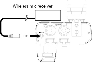
 INPUT 3 jack
This input jack is for mics and other recording devices.
This supports plug-in power (2.7 V).
 Battery holder release button
Press this button to remove the battery holder.
 USB port
This micro-B USB port is specifically for firmware updates. For instructions about updating, refer to the Firmware Update Manual for this unit that will be provided when a firmware update is released.
ATTENTION
This cannot be used to power the unit, for example.
 Battery holder
External batteries can be used to power this unit when, for example, power cannot be supplied from the camera, you do not want to use the camera battery or there are other limitations to power supply due to the camera battery, operating conditions or other factors.
 BATTERY POWERED switch
Set this switch to “ON” to power the unit with the external batteries, or set this to “OFF” to power the unit from the camera.
ATTENTION
When connecting the battery holder and turning the power on for the first time, set this switch to “OFF”.
Since the input sound will be muted when the BATTERY POWERED switch () is switched, stop recording with the camera temporarily beforehand.
 Battery type switch
Use this to set the type of battery used.
This setting is used to show the amount of remaining battery charge and determine if the unit has enough power for normal operation.
|
Ni-MH |
Use this setting for nickel-metal hydride batteries. |
|
Lithium |
Use this setting for lithium batteries. |
|
ALK |
Use this setting for alkaline batteries. |
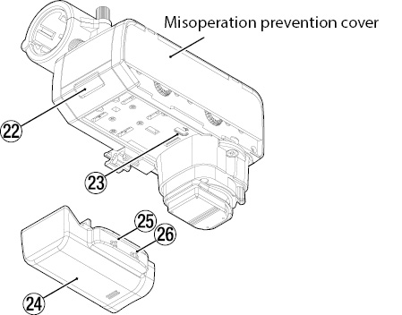
Accessory shoe attachment adapter parts
|
|
|
|
CA-XLR2d-C |
CA-XLR2d-F |
|
|
|
|
CA-XLR2d-N |
CA-XLR2d-AN |
Four types of adapters are available for different cameras.
Connect the adapter that matches the camera being used, and securely tighten the attachment screws. (You can do this replacement yourself.)
See “Changing accessory shoe attachment adapters” on page 8 for instructions about changing accessory shoe attachment adapters.
A list of cameras that have been confirmed for use with this unit is available on the TASCAM website (https://tascam.jp/int/product/ca-xlr2d/docs).
ATTENTION
Do not directly touch the connectors with hands.
Always turn the camera power off when connecting or disconnecting this unit with a camera.
After connecting this unit to a camera, tighten it securely to prevent it from falling off.
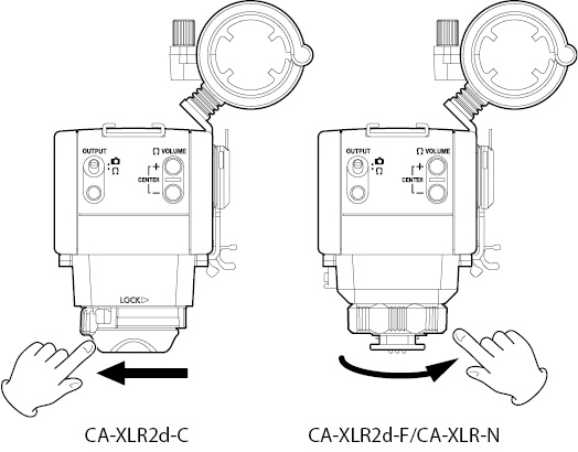
 Lock lever (CA-XLR2d-C)
To secure this unit to a camera, move the lock lever toward LOCK . (see “Connecting to a camera (CA-XLR2d-C/CA-XLR2d-F/CA-XLR2d-N)” on page 10)
NOTE
To release the lock lever, move it while pressing the lock button.
 Tightening dial (CA-XLR2d-F/CA-XLR2d-N/CA-XLR2d-AN)
To secure this unit to a camera, turn the tightening dial from right to left. (see “Connecting to a camera (CA-XLR2d-C/CA-XLR2d-F/CA-XLR2d-N)” on page 10)

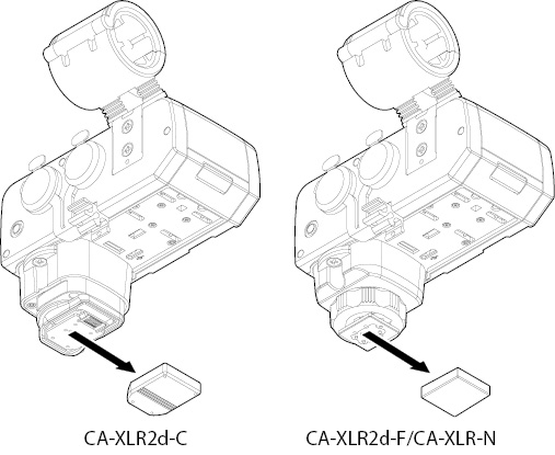
Changing accessory shoe attachment adapters
Change the accessory shoe attachment adapter to use an analog connection with this unit or switch to a camera by a different manufacturer.
For details about accessory shoe attachment adapters, see “ Accessory shoe mount adapter” on page 7.
Changing the accessory shoe attachment adapter
1.Use a Phillips head screwdriver to remove the 2 screws that affix the accessory shoe attachment adapter ().
.jpg)
2.Remove the accessory shoe attachment adapter from the unit.
3.Being careful to use the correct orientation, align the replacement accessory shoe adapter with the unit.
.jpg)
4.Use the 2 screws that were removed to affix the accessory shoe adapter.
.jpg)
ATTENTION
Attach a connector cover to the removed accessory shoe adapter. Failure to do so could result in this unit malfunctioning due to the ingress of foreign matter or connector damage, for example.
This unit can be powered in two ways: from a camera or using AA batteries.
Alkaline, nickel-metal hydride or lithium AA batteries can be used.
Use AA batteries when any of the following considerations apply to power supply from a camera.
Power supply from a camera cannot be received
Using the camera battery is undesirable
Power supply is limited due to conditions that include the camera battery or operating status
Using power supplied from a camera
Power can be supplied to the unit when a camera that can supply power is connected.
For information about cameras that support power supply, refer to the list of cameras that have been confirmed for operation on the TASCAM website (https://tascam.jp/int/product/ca-xlr2d/docs) or contact TASCAM Customer Support.
Install 2 AA batteries in the included battery holder, and attach it to the unit.
1.Slide the cover from the battery holder () to remove it. Install 2 AA batteries with their  and
and  marks as shown in the holder. Then reattach the cover.
.jpg)
2.Remove the battery holder connector cover.
.jpg)
3.Remove the bottom connector cover from the unit and attach the battery holder to the unit.
.jpg)
ATTENTION
If the BATTERY POWERED switch () on the battery holder was set to “ON” when it was connected to the unit, the switch must be set to “OFF” once and then back to “ON” in order to use battery power.
4.Set the battery type switch () according to the type of batteries being used.
.jpg)
5.Set the BATTERY POWERED switch () to “ON” to supply power from the batteries.
.jpg)
ATTENTION
Manganese dry cell batteries cannot be used with this unit.
This unit cannot recharge Ni-MH batteries. Use a commercially available recharger.
When not using the battery holder, attach the bottom connector cover to the unit. Using without this cover could result in this unit malfunctioning due to the ingress of foreign matter or connector damage, for example.
NOTE
A great amount of power is required to provide phantom power to condenser mics. If condenser mics are used while powering the unit with AA batteries, operation time will be shortened due to mic power consumption.
After preparing this unit, connect it to a camera.
ATTENTION
Always confirm that the power is off on both this unit and the camera before connecting them.
Do not hold this unit when lifting a connected device. Doing so could put excessive burden on the connection parts and damage this unit and the connected device.
Disconnect this unit from the connected device and store it when not in use. Not doing so could put excessive burden on the connection parts and damage this unit and the connected device.
Connecting to a camera
(CA-XLR2d-C/CA-XLR2d-F/CA-XLR2d-N)
1.Disengage the lock lever () or the tightening dial (), and remove the accessory shoe attachment adapter cover.
2.With the unit oriented correctly, mount the connector part to the camera accessory shoe, sliding it all the way in.
.jpg)
.jpg)
3.Using the lock lever () or the tightening dial (), attach this unit to the connected device securely.
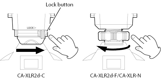
NOTE
To remove a CA-XLR2d-C, release the lock lever while pressing the lock button.
Connecting to a camera (CA-XLR2d-AN)
1.Loosen the tightening dial ().
.jpg)
2.With the unit oriented correctly, mount the connector part to the camera accessory shoe, sliding it all the way in.
.jpg)
.jpg)
3.Using the tightening dial (), attach this unit to the connected device securely.
.jpg)
4.Use the included 3.5mm (1/8”) stereo mini cable to connect the OUTPUT jack () of this unit with the camera input jack.
.jpg)
ATTENTION
Do not use with an analog connection to a camera when set to . If used with the VOLUME +/− buttons () near maximum level, excessive input could occur depending on the camera input specifications, possibly resulting in damage to the connected devices.
Power will not be supplied if the accessory shoe attachment adapter that is connected is not compatible with the camera or attachment is incomplete. To check, refer to the list of cameras that have been confirmed for operation on the TASCAM website (https://tascam.jp/int/product/ca-xlr2d/docs).
When not connected to a camera, attach the connector cover to the unit. Failure to do so could result in this unit malfunctioning due to the ingress of foreign matter or connector damage, for example.
5.Set the OUTPUT switch () to .
This section explains how to connect mics and other recording devices as well as various connection settings.
Connecting a single mic that uses phantom power
1.Loosen the mic holder screw and open the holder.
.jpg)
2.Place the mic in the holder, and close the holder while keeping the mic in place. Then, tighten the screw securely.
.jpg)
.jpg)
3.Connect the mic cable to the INPUT 1 jack () on this unit.
.jpg)
ATTENTION
Before connecting or disconnecting a mic or other recording device, turn this unit off.
Do not connect or disconnect mics when the INPUT 1 switch () is set to +48V. Doing so could cause a loud noise and might damage this unit and connected equipment.
Do not set the INPUT 1 switch () to “+48V” when connecting mics that do not require phantom power.
NOTE
If the cable is long, attach the cable to the cable holder so that it stays out of the way.
.jpg)
4.Set the SELECT switch () to “IN 1” and set the INPUT 1 switch () to “MIC” or “+48V”.
.jpg)
NOTE
The mic holder can be used to mount mics with 19–23 mm diameters.
The mic holder can be detached. Remove it with its screws if it is unneeded. (see “Removing the mic holder” on page 13)
Remove the 2 screws indicated by the arrows to remove the mic holder.
.jpg)
This section explains how to connect and use various devices.
Connecting two mics
.jpg)
.jpg)
When connecting a mic to the INPUT 2 jack () set the SELECT switch () to “IN 1+2” and set the INPUT 2 switch () according to the type of mic connected.
When using mics that require phantom power, set the INPUT 1 () and INPUT 2 () switches to “+48V”.
Connecting mics to the mini jack
.jpg)
When connecting a stereo lapel mic, for example, connect it to the INPUT 3 jack (), and set the SELECT switch () to “IN 3”.
NOTE
When the SELECT switch () is set to “IN 3”, the INPUT 1 switch () has no effect.
Connecting line level equipment
.jpg)
.jpg)
When connecting a mixer or other line level equipment, use XLR or TRS cables to connect it to this unit, and set the INPUT 1 () and INPUT 2 () switches to “LINE”.
Connecting headphones
.jpg)
To monitor analog audio signals, set the OUTPUT switch () to , and connect headphones or an earphone, for example, to the OUTPUT jack (). Then use the VOLUME +/− buttons () to adjust the volume.
TIP
By connecting headphones to this unit, the sound can be monitored with relatively less latency than the sound output from the camera headphone jack.
After completing preparation of connected devices turn on the power supply for this unit.
In order to have this unit operate under the control of the camera, operations and procedures according to the power supply and image capture mode of the camera are necessary. (When using a CA-AK1-AN, it will operate in standalone mode requiring AA batteries.)
CA-XLR2d-C/CA-XLR2d-F/CA-XLR2d-N
When power supplied from camera
1.Set the BATTERY POWERED switch () to “OFF”.
2.Turn the camera power on and set its operation mode to “video recording”.
This will start power supply from the camera, and the POWER SUPPLY indicator () will light.
The input meter shown on the camera display will move according to the input signal, allowing the transmission of audio to be confirmed.
NOTE
Depending on the specifications of the connected camera, an accessory connection indicator might appear on the camera display.
When using AA batteries
1.Set the BATTERY POWERED switch () to “OFF”.
2.Turn the camera power on and set its operation mode to “video recording”.
This will start power supply from the camera, and the POWER SUPPLY indicator () will light.
NOTE
Depending on the specifications of the connected camera, an accessory connection indicator might appear on the camera display.
3.Set the BATTERY POWERED switch () to “ON”.
This will start power supply from the AA batteries, and the POWER SUPPLY .jpg) indicator () will light.
indicator () will light.
The input meter shown on the camera display will move according to the input signal, allowing the transmission of audio to be confirmed.
ATTENTION
Since the CA-XLR2d-C, CA-XLR2d-F and CA-XLR2d-N require control from a camera, they cannot be operated using just AA batteries when there is no power from a camera.
Since the input sound will be muted when the BATTERY POWERED switch () is switched, stop recording with the camera temporarily beforehand.
When the camera is turned on with the CA-XLR2d attached, or when switching from still image modeto movie mode, it takes approximately 4 seconds for audio from the CA-XLR2d to be input.
1.Set the BATTERY POWERED switch () to “OFF”.
2.Turn the camera power on and set its operation mode to “video recording”.
3.Set the BATTERY POWERED switch () to “ON”.
This will start power supply from the AA batteries, and the POWER SUPPLY indicator () will light.
The input meter shown on the camera display will move according to the input signal, allowing the transmission of audio to be confirmed.
ATTENTION
When using a CA-XLR2d-AN, if the BATTERY POWERED switch () is set to “ON”, the batteries will be used. Set it to “OFF” when done using.
After confirming on the camera that audio is being received, adjust the input volume controls (/) while checking the input meters shown on the camera display.
.jpg)
Adjust the sound while monitoring it.
TIP
By connecting headphones to this unit, the sound can be monitored with relatively less latency than the sound output from the camera headphone jack.
Monitoring through this unit
(CA-XLR2d-C/CA-XLR2d-F/CA-XLR2d-N)
Set the OUTPUT switch () to and monitor the sound.
NOTE
When the OUTPUT switch () is set to , the VOLUME +/− buttons () cannot be used to adjust the volume.
Monitoring through this unit (CA-XLR2d-AN)
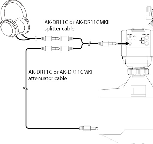
A splitter cable is necessary to monitor analog audio with a CA-XLR2d-AN.
Set the OUTPUT switch () to , and use TASCAM AK-DR11C or AK-DR11CMKII splitter and attenuator cables to connect the OUTPUT jack () to the camera and to headphones or an earphone, for example.
ATTENTION
Do not use for an analog connection to a camera when set to without an attenuator cable. If used with the VOLUME +/− buttons () near maximum level, excessive input could occur depending on the camera input specifications, possibly resulting in damage to the connected devices.
Touching this unit during recording might cause noise to be recorded.
During video recording, noises from operation and other activity of the camera and lens might be recorded.
This unit might not function properly near radio towers and other sources that generate strong radio waves or magnetism.
Always hold this unit firmly when operating its setting switches and changing the mic orientation. Applying a strong force to the connection parts could damage this unit and the connected device.
TIP
To maximize the performance of this unit’s mic preamps, we recommend setting this unit’s volume as high as possible.
Monitoring through the camera
.jpg)
If you are having trouble with the operation of this unit, please try the following before seeking repair.
If these measures do not solve the problem, please contact the store where you bought the unit or TASCAM customer support service.
The unit will not turn on
Confirm that it has been mounted completely on the camera accessory shoe.
Confirm that the batteries are loaded correctly and still have power.
If the BATTERY POWERED switch () on the battery holder was set to “ON” when it was connected to the unit, the switch must be set to “OFF” once and then back to “ON” in order to use battery power.
No sound is output
If the POWER SUPPLY indicator () is blinking rapidly, the power will soon turn off because the battery charge has become very low. Replace the batteries.
Confirm the headphone output level is not minimized.
An error appears on the camera after it is turned on / Power to this unit is interrupted
Confirm that it has been mounted completely on the camera accessory shoe.
Turn the camera power off and on once to restart it.
Depending on the dynamic mic, setting the INPUT 1 () or INPUT 2 () switch to “+48V” could result in excessive current drawn for phantom power supply. This could cause the power to be interrupted due to limitations of the camera power supply. For this reason, when using dynamic mics, set the INPUT 1 () and INPUT 2 () switches to “MIC”.
Since this could be due to limitations* of the camera power supply, use the included battery holder () to power it using AA batteries. (see “Using AA batteries” on page 9)
Depending on the power consumption of the mics being used, errors could result due to limitations* of the camera power supply. Change the mics connected to the unit.
*Check the list of cameras that have been confirmed for operation for information about camera power supply limitations.
The OL (overload) indicators for both INPUT 1 and INPUT 2 blink when the power is turned on
If the firmware versions for the unit and the accessory shoe attachment adapter do not match, both OL indicators () will blink. The cause might be that the unit was updated with the accessory shoe attachment adapter disconnected. Connect the accessory shoe attachment adapter to the CA-XLR2d unit and update the firmware again.
Battery consumption time is fast
Set the type of battery being used because the remaining battery charge is monitored according to the battery type.
Input sound is muted
If the camera power is turned on while the INPUT switches (/) are set to “+48V”, analog power might be interrupted and the input sound muted due to camera power supply limitations. Always check that the camera meters are moving before starting video recording. If the sound is muted, use batteries to power this unit or switch to mics that use less power.
Sampling frequencies*
48, 96 kHz
Quantization bit depths*
16-bit/24-bit
*Sampling frequency and quantization bit depths depend on the camera settings
Input channels
2 channels maximum
Mic inputs (balanced)
INPUT 1/2 jacks (phantom power supported by XLR only)
Connectors:
XLR-3-31 equivalent (1: GND, 2: HOT, 3: COLD)
6.3mm (1/4”) standard TRS jacks (Tip: HOT, Ring: COLD, Sleeve: GND)
When INPUT 1/2 switch set to MIC
Input impedance: 2kΩ or more
Maximum input level: +6 dBu (when ATT switch set to “46dB”)
Minimum input level: −60 dBu (when ATT switch set to “0dB”)
Gain range: 66 dB
When INPUT 1/2 switch set to LINE
Input impedance: 10kΩ or more
Maximum input level: +24 dBu
Nominal input level: +4 dBu
Gain range: 66 dB
0 dBu=0.775 Vrms
Mic input (unbalanced)
INPUT 3 jack (supports plug-in power)
Connector: 3.5mm (1/8”) stereo mini jack
Input impedance: 2kΩ or more
Maximum input level: +6 dBV (when ATT switch set to “46dB”)
Minimum input level: −60 dBV (when ATT switch set to “0dB”)
Gain range: 66 dB
Plug-in power: 2.7 V
0 dBV=1.0 Vrms
Headphone/camera output (unbalanced)
OUTPUT jack
Connector: 3.5mm (1/8”) stereo mini jack
At maximum output when OUTPUT switch set to :
8 mW (distortion 0.1% or less, into 16Ω load)
When OUTPUT switch set to :
0.29 Vrms (fixed)
Recommended headphone impedance: 16–250 Ω
Mic amp EIN (equivalent input noise)
−120 dBu or less (150Ω termination, maximum gain, A-weighted)
Dynamic range
95 dB or higher (22 kHz LPF + A-weighted)
Frequency response
20 Hz – 20 kHz: +0.5 dB/−1.0 dB (XLR to digital input, 48kHz sampling frequency)
20 Hz – 40 kHz: +0.5 dB/−1.0 dB (XLR to digital input, 96kHz sampling frequency)
Power
2 AA batteries (alkaline, NiMH or lithium-ion)
Supplied through accessory shoe of compatible camera
Power consumption
2.0 W (maximum)
Battery operation time (continuous operation)
Using alkaline batteries (EVOLTA)
|
Use conditions |
Operation time |
|
Condenser mic connected to INPUT 1 jack Phantom power used (2 mA) |
About 4 hours |
|
Condenser mic connected to INPUT 1 jack Phantom power used (5mA) |
About 3 hours |
|
Dynamic mics connected to INPUT 1 and INPUT 2 jacks Phantom power unused |
About 6.5 hours |
|
TASCAM TM-200SG connected to INPUT 1 jack Phantom power used |
About 4 hours |
Other unit settings: input volume centered, ATT switch at “0dB”, LEVEL switch at “MAN”, LIMITER switch at “OFF”
Using NiMH battery (eneloop)
|
Use conditions |
Operation time |
|
Condenser mic connected to INPUT 1 jack Phantom power used (2 mA) |
About 5 hours |
|
Condenser mic connected to INPUT 1 jack Phantom power used (5mA) |
About 4 hours |
|
Dynamic mics connected to INPUT 1 and INPUT 2 jacks Phantom power unused |
About 7 hours |
|
TASCAM TM-200SG connected to INPUT 1 jack Phantom power used |
About 5 hours |
Other unit settings: input volume centered, ATT switch at “0dB”, LEVEL switch at “MAN”, LIMITER switch at “OFF”
Using lithium-ion batteries (Energizer Ultimate Lithium)
|
Use conditions |
Operation time |
|
Condenser mic connected to INPUT 1 jack Phantom power used (2 mA) |
About 10 hours |
|
Condenser mic connected to INPUT 1 jack Phantom power used (5mA) |
About 8 hours |
|
Dynamic mics connected to INPUT 1 and INPUT 2 jacks Phantom power unused |
About 14.5 hours |
|
TASCAM TM-200SG connected to INPUT 1 jack Phantom power used |
About 10 hours |
Other unit settings: input volume centered, ATT switch at “0dB”, LEVEL switch at “MAN”, LIMITER switch at “OFF”
ATTENTION
When using phantom power, the operation time might be reduced depending on the mics being used.
Dimensions / Weight
CA-XLR2d-C:
88.2mm (W) x 119.1mm (H) x 110.0 mm (D) / 341 g
(not including protrusions, mic holder attached, battery holder not attached)
CA-XLR2d-F:
88.2mm (W) x 119.1mm (H) x 110.0 mm (D) / 331 g
(not including protrusions, mic holder attached, battery holder not attached)
CA-XLR2d-N:
88.2mm (W) x 126.2mm (H) x 110.0 mm (D) / 341 g
(not including protrusions, mic holder attached, battery holder not attached)
CA-XLR2d-AN:
88.2mm (W) x 119.1mm (H) x 110.0 mm (D) / 357 g
(not including protrusions or batteries, mic holder attached, battery holder attached)
Operating temperature range
0 - 40°C (32 - 104°F)
CA-XLR2d-C
.jpg)
CA-XLR2d-F
.jpg)
CA-XLR2d-N
.jpg)
CA-XLR2d-AN
.jpg)
Illustrations in this reference manual might differ in part from the actual product.
Specifications and external appearance might be changed without notification to improve the product.
Software Licensing
CMSIS Core header files
Copyright (C) 2009-2015 ARM Limited.
All rights reserved.
Redistribution and use in source and binary forms, with or without modification, are permitted provided that the following conditions are met:
-Redistributions of source code must retain the above copyright notice, this list of conditions and the following disclaimer.
-Redistributions in binary form must reproduce the above copyright notice, this list of conditions and the following disclaimer in the documentation and/or other materials provided with the distribution.
-Neither the name of ARM LIMITED nor the names of its contributors may be used to endorse or promote products derived from this software without specific prior written permission.
THIS SOFTWARE IS PROVIDED BY THE COPYRIGHT HOLDERS AND CONTRIBUTORS “AS IS” AND ANY EXPRESS OR IMPLIED WARRANTIES, INCLUDING, BUT NOT LIMITED TO, THE IMPLIED WARRANTIES OF MERCHANTABILITY AND FITNESS FOR A PARTICULAR PURPOSE ARE DISCLAIMED. IN NO EVENT SHALL THE COPYRIGHT OWNER OR CONTRIBUTORS BE LIABLE FOR ANY DIRECT, INDIRECT, INCIDENTAL, SPECIAL, EXEMPLARY, OR CONSEQUENTIAL DAMAGES (INCLUDING, BUT NOT LIMITED TO, PROCUREMENT OF SUBSTITUTE GOODS OR SERVICES; LOSS OF USE, DATA, OR PROFITS; OR BUSINESS INTERRUPTION) HOWEVER CAUSED AND ON ANY THEORY OF LIABILITY, WHETHER IN CONTRACT, STRICT LIABILITY, OR TORT (INCLUDING NEGLIGENCE OR OTHERWISE) ARISING IN ANY WAY OUT OF THE USE OF THIS SOFTWARE, EVEN IF ADVISED OF THE POSSIBILITY OF SUCH DAMAGE.
KSDK Peripheral Drivers
Copyright (c) 2013 - 2015 Freescale Semiconductor, Inc.
All rights reserved.
Redistribution and use in source and binary forms, with or without modification, are permitted provided that the following conditions are met:
-Redistributions of source code must retain the above copyright notice, this list of conditions and the following disclaimer.
-Redistributions in binary form must reproduce the above copyright notice, this list of conditions and the following disclaimer in the documentation and/or other materials provided with the distribution.
-Neither the name of Freescale Semiconductor, Inc. nor the names of its contributors may be used to endorse or promote products derived from this software without specific prior written permission.
THIS SOFTWARE IS PROVIDED BY THE COPYRIGHT HOLDERS AND CONTRIBUTORS “AS IS” AND ANY EXPRESS OR IMPLIED WARRANTIES, INCLUDING, BUT NOT LIMITED TO, THE IMPLIED WARRANTIES OF MERCHANTABILITY AND FITNESS FOR A PARTICULAR PURPOSE ARE DISCLAIMED. IN NO EVENT SHALL THE COPYRIGHT HOLDER OR CONTRIBUTORS BE LIABLE FOR ANY DIRECT, INDIRECT, INCIDENTAL, SPECIAL, EXEMPLARY, OR CONSEQUENTIAL DAMAGES (INCLUDING, BUT NOT LIMITED TO, PROCUREMENT OF SUBSTITUTE GOODS OR SERVICES; LOSS OF USE, DATA, OR PROFITS; OR BUSINESS INTERRUPTION) HOWEVER CAUSED AND ON ANY THEORY OF LIABILITY, WHETHER IN CONTRACT, STRICT LIABILITY, OR TORT (INCLUDING NEGLIGENCE OR OTHERWISE) ARISING IN ANY WAY OUT OF THE USE OF THIS SOFTWARE, EVEN IF ADVISED OF THE POSSIBILITY OF SUCH DAMAGE.
KSDK Flash / NVM
Copyright (c) 2010 - 2015 Freescale Semiconductor, Inc.
All rights reserved.
Redistribution and use in source and binary forms, with or without modification, are permitted provided that the following conditions are met:
-Redistributions of source code must retain the above copyright notice, this list of conditions and the following disclaimer.
-Redistributions in binary form must reproduce the above copyright notice, this list of conditions and the following disclaimer in the documentation and/or other materials provided with the distribution.
-Neither the name of Freescale Semiconductor, Inc. nor the names of its contributors may be used to endorse or promote products derived from this software without specific prior written permission.
THIS SOFTWARE IS PROVIDED BY THE COPYRIGHT HOLDERS AND CONTRIBUTORS “AS IS” AND ANY EXPRESS OR IMPLIED WARRANTIES, INCLUDING, BUT NOT LIMITED TO, THE IMPLIED WARRANTIES OF MERCHANTABILITY AND FITNESS FOR A PARTICULAR PURPOSE ARE DISCLAIMED. IN NO EVENT SHALL THE COPYRIGHT HOLDER OR CONTRIBUTORS BE LIABLE FOR ANY DIRECT, INDIRECT, INCIDENTAL, SPECIAL, EXEMPLARY, OR CONSEQUENTIAL DAMAGES (INCLUDING, BUT NOT LIMITED TO, PROCUREMENT OF SUBSTITUTE GOODS OR SERVICES; LOSS OF USE, DATA, OR PROFITS; OR BUSINESS INTERRUPTION) HOWEVER CAUSED AND ON ANY THEORY OF LIABILITY, WHETHER IN CONTRACT, STRICT LIABILITY, OR TORT (INCLUDING NEGLIGENCE OR OTHERWISE) ARISING IN ANY WAY OUT OF THE USE OF THIS SOFTWARE, EVEN IF ADVISED OF THE POSSIBILITY OF SUCH DAMAGE.
KSDK H/W Abstraction Layer (HAL)
Copyright (c) 2013 - 2015 Freescale Semiconductor, Inc.
All rights reserved.
Redistribution and use in source and binary forms, with or without modification, are permitted provided that the following conditions are met:
-Redistributions of source code must retain the above copyright notice, this list of conditions and the following disclaimer.
-Redistributions in binary form must reproduce the above copyright notice, this list of conditions and the following disclaimer in the documentation and/or other materials provided with the distribution.
-Neither the name of Freescale Semiconductor, Inc. nor the names of its contributors may be used to endorse or promote products derived from this software without specific prior written permission.
THIS SOFTWARE IS PROVIDED BY THE COPYRIGHT HOLDERS AND CONTRIBUTORS “AS IS” AND ANY EXPRESS OR IMPLIED WARRANTIES, INCLUDING, BUT NOT LIMITED TO, THE IMPLIED WARRANTIES OF MERCHANTABILITY AND FITNESS FOR A PARTICULAR PURPOSE ARE DISCLAIMED. IN NO EVENT SHALL THE COPYRIGHT HOLDER OR CONTRIBUTORS BE LIABLE FOR ANY DIRECT, INDIRECT, INCIDENTAL, SPECIAL, EXEMPLARY, OR CONSEQUENTIAL DAMAGES (INCLUDING, BUT NOT LIMITED TO, PROCUREMENT OF SUBSTITUTE GOODS OR SERVICES; LOSS OF USE, DATA, OR PROFITS; OR BUSINESS INTERRUPTION) HOWEVER CAUSED AND ON ANY THEORY OF LIABILITY, WHETHER IN CONTRACT, STRICT LIABILITY, OR TORT (INCLUDING NEGLIGENCE OR OTHERWISE) ARISING IN ANY WAY OUT OF THE USE OF THIS SOFTWARE, EVEN IF ADVISED OF THE POSSIBILITY OF SUCH DAMAGE.
KSDK MKL17Z4
Copyright (c) 1997 - 2015 Freescale Semiconductor, Inc.
All rights reserved.
Redistribution and use in source and binary forms, with or without modification, are permitted provided that the following conditions are met:
-Redistributions of source code must retain the above copyright notice, this list of conditions and the following disclaimer.
-Redistributions in binary form must reproduce the above copyright notice, this list of conditions and the following disclaimer in the documentation and/or other materials provided with the distribution.
-Neither the name of Freescale Semiconductor, Inc. nor the names of its contributors may be used to endorse or promote products derived from this software without specific prior written permission.
THIS SOFTWARE IS PROVIDED BY THE COPYRIGHT HOLDERS AND CONTRIBUTORS “AS IS” AND ANY EXPRESS OR IMPLIED WARRANTIES, INCLUDING, BUT NOT LIMITED TO, THE IMPLIED WARRANTIES OF MERCHANTABILITY AND FITNESS FOR A PARTICULAR PURPOSE ARE DISCLAIMED. IN NO EVENT SHALL THE COPYRIGHT HOLDER OR CONTRIBUTORS BE LIABLE FOR ANY DIRECT, INDIRECT, INCIDENTAL, SPECIAL, EXEMPLARY, OR CONSEQUENTIAL DAMAGES (INCLUDING, BUT NOT LIMITED TO, PROCUREMENT OF SUBSTITUTE GOODS OR SERVICES; LOSS OF USE, DATA, OR PROFITS; OR BUSINESS INTERRUPTION) HOWEVER CAUSED AND ON ANY THEORY OF LIABILITY, WHETHER IN CONTRACT, STRICT LIABILITY, OR TORT (INCLUDING NEGLIGENCE OR OTHERWISE) ARISING IN ANY WAY OUT OF THE USE OF THIS SOFTWARE, EVEN IF ADVISED OF THE POSSIBILITY OF SUCH DAMAGE.
|
0725. MA-3423D |

.jpg)
.jpg)
.jpg)
.jpg)