|
|
D01461820C |

Linear PCM Recorder
Owner's Manual
V1.11
|
|
D01461820C |
Linear PCM Recorder
Owner's Manual
V1.11
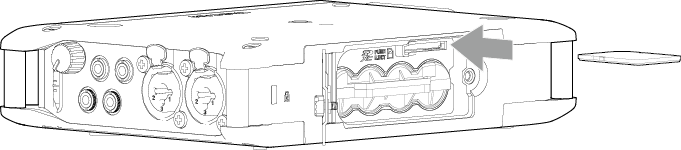
Open the back cover and insert an SD card into the slot as shown in the illustration until it clicks into place.
To remove an SD card, press it in gently and then pull it out.
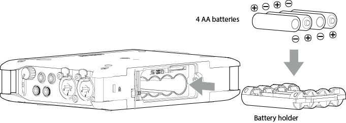
1.Open the rear cover and remove the battery holder.

2.Install batteries with their  and
and  marks as shown in the battery holder. Then, reinstall the case in the unit.
3.Close the back cover and tighten the screw.
NOTE
 See “3-3. Preparing the power supply” for details about power supplies.
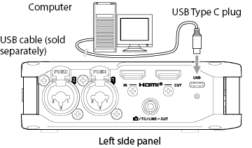
If a computer is going to be used only to supply power, a driver does not need to be installed.
Use a cable that supports data transmission to connect with the USB port of a computer or another device.
We recommend connecting it to a USB Type-C port on a computer or other device.
|
|
|
|
|
|
|
|
|
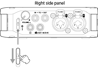
Release the switch after the start up screen appears. |
|
|
|
|
|
|
|
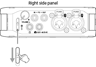
Release the switch after the POWER OFF screen appears. |
|
CAUTION Always use the If the unit is not able to conduct shutdown procedures properly, recording data, settings and other changes could be lost. Lost data and settings cannot be restored. |
NOTE
The unit cannot be turned off when it is recording.
Using the touchscreen
Select
Scroll the screen.
Confirm
Tap the desired setting item.
Using the DATA dial
Select
Turn the DATA dial to highlight the desired item.
Confirm
Press the DATA dial to confirm.
TIP
By pressing the DATA dial while turning it, cursor movement and parameter adjustment can be accelerated.
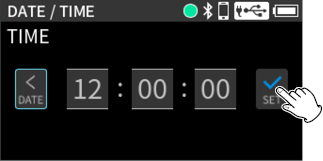
Whenever the date and time have been reset, the DATE/TIME Screen will open.
After setting the date and time, tap “SET” to confirm.
Formatting (initializing) SD cards
SD cards must be formatted by this unit before they can be used with it.
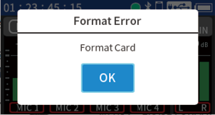
The following message will appear if an unformatted card is loaded.
Tap the OK button to start quick formatting.
After formatting completes, the Home Screen will open.
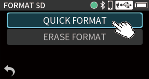
The following setting item can also be used for formatting.
MENU > FORMAT SD
1.Tap “QUICK FORMAT” or “ERASE FORMAT”.
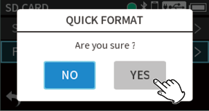
2.Tap the “YES” button.
|
CAUTION Formatting will erase all the data on the SD card. Back up to a computer, for example before formatting a card. |
NOTE
Using the “ERASE FORMAT” option might improve writing performance that has decreased due to repeated use. If “Write Timeout” or “Card slow Check BOF MARK” messages appear during recording, format the card with “ERASE FORMAT”.
ERASE FORMAT takes more time than QUICK FORMAT.
When recording/playback stopped

Up to 4 inputs can be recorded.
Making input settings for each input
Follow one of the procedures below to open the Input Settings Screen.
When the Home Screen is open, press the 1, 2, 3 or 4 button on the unit.
Tap the desired track when the Home Screen is open.

The Input Settings Screen has multiple pages.
Tap the arrows ( /
/  ) at the bottom of the screen to move between pages.
Making various settings and monitor adjustments
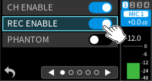
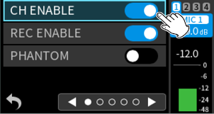
Set this using CH ENABLE.
Channels can be enabled (on) or disabled (off).

Options: Off, On (default)
Set this using REC ENABLE.
Channels can be enabled (on) or disabled (off) for recording.
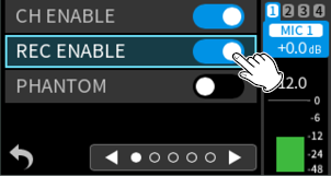
Options: Off, On (default)
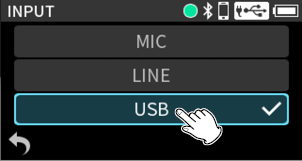
Set this using INPUT.
The input sources of channels can be set.
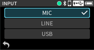
When using input jacks 1–4, select “MIC” or “LINE”.
When using  /EXT IN (3/4), select “EXT”.
When using computer output as audio input to this unit, select “USB”. (12-4. Using as an audio interface)
Set this using PHANTOM.
Make this setting when using mics that require phantom power.

Options: Off (default), On
Setting plug-in power (EXT IN 3/4 jack)
Set this using PLUG IN POWER.
Options: OFF (default), 2.5V, 5V
When connecting a mic that requires plug-in power, set this to “2.5V” or “5V” according to the specifications of that mic.
|
CAUTION 3.5mm TS cables cannot be used. |
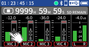
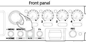
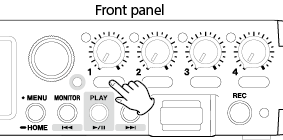
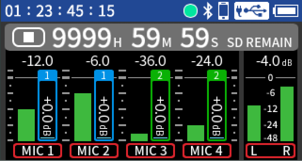
Setting input levels / Adjusting monitoring volume
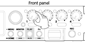
Turn the input level adjustment knobs to adjust the audio signal levels recorded in recording files.

While watching the level meters, adjust the input level adjustment knobs so that levels average around −12 dB and the peak indicators do not light. (5-5. OTHER SETTINGS)
If a knob’s position is different from its level setting value, the knob will function after it is moved to the position of the set value.
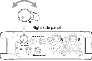
Adjusting the headphone output volume
Use the volume knob on the right side to adjust the volume output from the  (headphone) jack and with wireless audio monitoring (using an AK-BT2 sold separately).
|
|
|
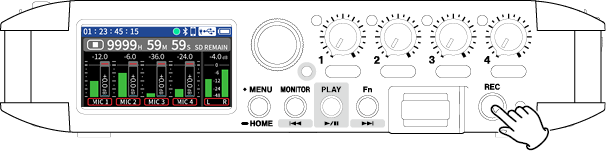
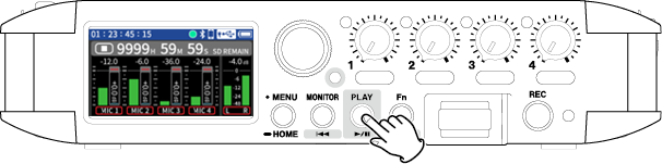
Press the REC button. |
|
|
|
|
|
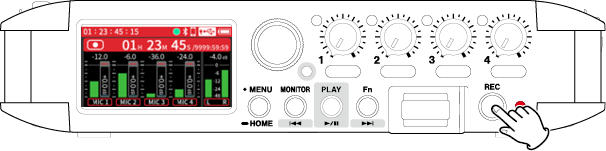
Recording |
|
|
|
Press and hold the REC button until recording stops. |
|
|
|
|
|
|
|
|
Stopped |
|
|
|
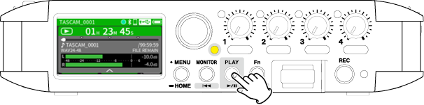
Press the |
|
|
|
|
|
Current project during playback The transport indicator will light. During playback, the MONITOR button will function as |
|
|
|
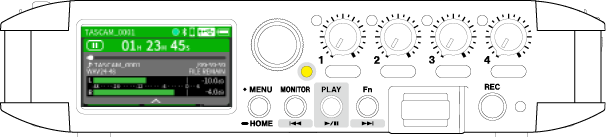
Press the |
|
|
|
|
|
Stopped |
|
|
|
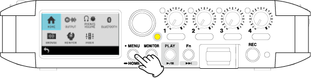
Press the MENU button and select HOME. Or, press and hold the MENU button. |
|
|
|
|
|
The transport indicator will become unlit, and the Home Screen will reopen. |
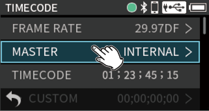
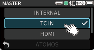
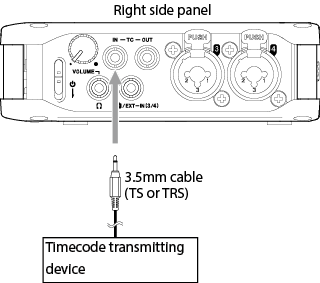
Receiving timecode using a cable
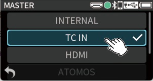
Press the MENU button and set TIMECODE > MASTER to “TC IN”.
|
|
|
|
|
|
To receive timecode from the TC IN jack, input must be in the specified level range for LTC.
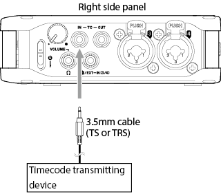
Use a 3.5mm cable (TS or TRS) to connect the output of the timecode transmitting device to the TC IN connector on this unit.
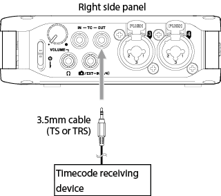
Outputting timecode using a cable
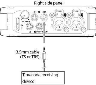
Press the MENU button and set TIMECODE > TC MODE to “FREE RUN”.
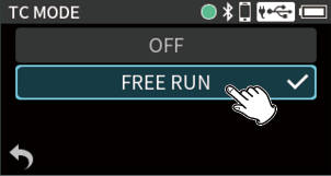
Use a 3.5mm cable (TS or TRS) to connect the input of the timecode receiving device to the TC OUT connector on this unit.
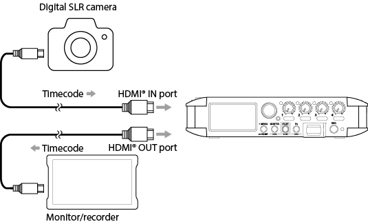
Synchronizing with a camera using HDMI®
Press the MENU button and set TIMECODE > MASTER to “HDMI”.
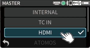
Connecting with a camera using HDMI®
This unit can be synchronized with a camera's clock by connecting the camera's HDMI® output to this unit's HDMI® IN port. Moreover, HDMI® timecode can be received from a camera.
Thank you very much for purchasing the TASCAM FR-AV4.
Before using this unit, read this Owner's Manual carefully so that you will be able to use it correctly and enjoy working with it for many years. After you have finished reading this manual, please keep it in a safe place for future reference.
You can also download this Owner’s Manual from the TASCAM website.
|
|
FR-AV4 |
This product includes the following items.
Take care when opening the package to avoid damaging the items. Keep the box and packing materials for transportation in the future.
Please contact the store where you purchased this unit if any of these items are missing or have been damaged during transportation.
Main unit × 1
Safety Guide (with warranty) × 1
TASCAM ID registration guide × 1
1-2.Accessories sold separately
This product does not include the following items.
Please purchase any that you need for your uses.
SD card
Batteries
AC adapter
Bluetooth® adapter (AK-BT2)
USB cable
HDMI® cable
Extra battery holders (BH-4AA)
An SD card is necessary to record and play files with this unit. Prepare one for use.
This unit can use SD cards that are Class 10 or higher and compatible with SD, SDHC or SDXC standards.
A list of SD cards that have been confirmed for use with this unit can be found by accessing the TASCAM website. You can also contact TASCAM customer support service.
https://tascam.jp/int/product/FR-AV4/docs
To power this unit with batteries, prepare batteries of one of the following types.
AA alkaline batteries × 4
AA nickel-metal hydride batteries × 4
AA lithium batteries × 4
This is necessary to operate this unit using AC power.
We highly recommend using the PS-P520U AC adapter (sold separately) that is designed for use with this unit. When using another external power supply device, use one that meets the following specifications.
Supplied voltage: 5 V
Supplied current: 1.5 A or more
Using a power supply device with specifications other than the above could cause malfunction, overheating, fire or other problems.
If trouble should occur, stop using the unit and contact the retailer where you purchased it or a TASCAM customer support service to request repair.
NOTE
This unit does not have a battery charging function when using an AC adapter.
AK-BT2 Bluetooth® adapter overview
Installing an AK-BT2 in this unit enables timecode synchronization with products made by Atomos as well as wireless remote control using smartphones and tablets.*
Input sounds can be monitored and playback sounds can be listened to wirelessly by connecting Bluetooth headphones or speakers.
NOTE
Wireless timecode, wireless remote control and wireless audio monitoring can be used simultaneously.
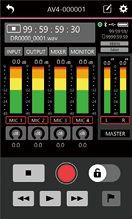
* The TASCAM RECORDER CONNECT remote control app can be used to simultaneously control and monitor up to 5 units.
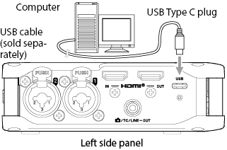
USB cables (for communication and data transmission)
A USB cable must be prepared to connect this unit to a computer (Windows/Mac) or smartphone. (We recommend a product that is USB-IF certified.)
This unit has a USB Type-C port.
Prepare a USB cable suitable for the USB port of the computer or smartphone being used.
Connecting to an iOS device with a lightning port
A genuine Apple Lightning to USB Camera Adapter and a commercially-available Type-A to Type-C cable are necessary.
USB cables designed only for charging cannot be used.
HDMI® cables (Ver. 2.1 recommended)
Use these for HDMI® timecode synchronization.
Use these for connection to digital single lens reflex cameras (DSLR), monitors and recorders.
The unit has one battery holder installed.
Battery replacement can be conducted more quickly by preparing another battery holder.
Dual A/D converters enable 32-bit float recording
– Recording formats: 24-bit and 32-bit float, 48, 96 and 192 kHz
Recording of 6 tracks (4 tracks + stereo mix)
4 XLR/TRS combo jacks with TASCAM Ultra HDDA mic preamps that provide high audio quality with −127dBu EIN
Timecode support includes generator function, input and output, and jam sync
Built-in TCXO realizes high-precision synchronization with no more than 1 frame error per 24 hours
Atomos products and Bluetooth wireless timecode synchronization supported*
Synchronization functions using HDMI® connections
– Audio recording starting/stopping coordinated with camera video recording starting/stopping
– Image and sound lags can even be eliminated with cameras that do not support timecode by using HDMI® clock
– HDMI® timecode synchronization
– Transport operations and audio transmission using FR-AV4 cascade connections
– 4K and 8K video pass-through supported
Wireless Bluetooth audio monitoring*
Support for SDXC cards up to 512 GB
Simultaneous operation of up to 5 supported devices from the TASCAM RECORDER CONNECT app*
1.9” LCD touchscreen and easy-to-use jog wheel
Low-cut filter, EQ, limiter and noise gate functions
Input and output delay functions (0–300 msec)
3.5mm stereo mini jack camera/external input (with plug-in power support)
3.5mm stereo mini jack headphone and camera/timecode/line out jacks
Ambisonic audio recording in A and B formats (AmbiX, FuMa) supported
6-in/2-out USB audio interface functions with 32-bit float support
Auto file save function automatically saves recording data every 20 seconds while recording
Tone generator function is convenient when adjusting the relative levels of different equipment
Powered by 4 AA batteries, a portable USB battery or a PS-P520U AC adapter (sold separately)
Includes a BH-4AA battery holder (additional BH-4AA available for quick and easy battery swaps)
Camera screw enables use with camera rigs
* This requires a separate AK-BT2 Bluetooth adapter. AK-BT1 adapters are not supported.
1-4.Conventions used in this manual
We use the following conventions in this manual.
SD/SDHC/SDXC memory cards are referred to as “SD cards”.
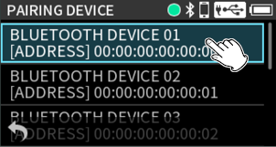
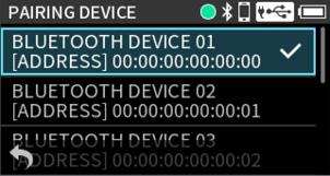
Smartphones, tablets and other devices connected to this unit using Bluetooth are called “Bluetooth devices”.
Files created during a single recording are referred to collectively as a project.
The project that is currently selected is called the “current project”.
Characters that appear on the display are shown like this: “OK”.
References to “iOS” in this document also include “iPadOS”.
As necessary, additional information is provided under TIP, NOTE and CAUTION headings.
TIP
These are tips about how to use the unit.
NOTE
These provide additional explanations and describe special cases.
CAUTION
Failure to follow these instructions could result in damage to equipment or lost data, for example.
 CAUTION
Failure to follow these instructions could result in injury.
|
Information is given about products in this manual only for the purpose of example and does not indicate any guarantees against infringements of third-party intellectual property rights and other rights related to them. TEAC Corporation will bear no responsibility for infringements on third-party intellectual property rights or their occurrence because of the use of these products. |
|
Properties copyrighted by third parties cannot be used for any purpose other than personal enjoyment and the like without the permission of the right holders recognized by copyright law. Always use this equipment properly. TEAC Corporation will bear no responsibility for rights infringements committed by users of this product. |
|
It is highly recommended that you shall avoid using the Media such as those not used for years or used after a long period of use or those with mold, blots, stickiness, folds, creases or twists.
It is highly recommended that you shall take appropriate measures to prepare for the unexpected loss of data along with the Copyright Act of your country or region. |
SD cards formatted by this unit are optimized to improve performance during recording. Use this unit to format the SD cards to be used with it. Errors might occur when recording with this unit using an SD card formatted by a computer or another device.

SD cards have write-protection switches that prevent writing new data to them.
File recording and editing will not be possible if the protect switch is moved to the LOCK position. Move the switch to the unlocked position in order to record, erase and otherwise edit data on the card.
1-6.Precautions for placement and use
The operating temperature range of this unit is 0–40 °C.
Do not install this unit in the following types of locations. Doing so could make the sound quality worse or cause malfunction.
Locations with frequent vibrations
Near windows or other places exposed to direct sunlight
Near heaters or other extremely hot places
Extremely cold places
Very humid or poorly ventilated places
Very dusty places
Install the unit so that it is level.
To enable good heat dissipation, do not place anything on top of the unit.
Do not place the unit on top of a power amplifier or other device that generates heat.
1-7.Beware of condensation
Condensation could occur if the unit is moved from a cold place to a warm place, it is used immediately after a cold room has been heated or it is otherwise exposed to a sudden temperature change.
To prevent this, or if this occurs, let the unit sit for one or two hours at the new room temperature before using it.
Use a dry soft cloth to wipe the unit clean. Do not wipe with chemical cleaning cloths, thinner, alcohol or other chemical agents. Doing so could damage the surface or cause discoloration.
1-9.About TASCAM customer support service
TASCAM products are supported and warrantied only in their country/region of purchase.
To receive support after purchase, on the TASCAM Distributors list page of the TEAC Global Site, search for the local company or representative for the region where you purchased the product and contact that organization.
When making inquiries, the address (URL) of the shop or web shop where it was purchased and the purchase date are required. Moreover, the warranty card and proof of purchase might also be necessary.
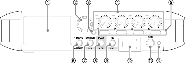
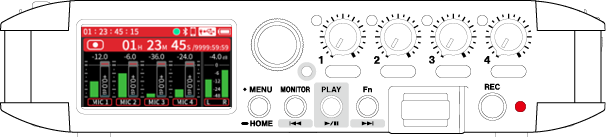
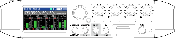
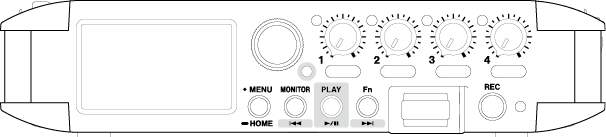
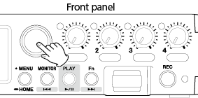
 Touchscreen
Tap and swipe the screen being shown to operate it.
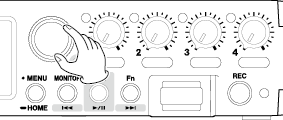
 DATA dial (ENTER)
Turn to select items and change values on settings screens.
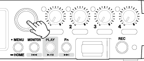
 Transport indicator
This lights during playback. When lit, the  ,
,  and
and  button functions become available.
 INPUT Level knobs and peak indicators
INPUT Level knobs
Use these to adjust the input levels of channels 1–4.
Peak indicators
If a input level exceeds the peak level, that peak indicator will light.
 1–4 buttons
Press these briefly to open the input settings screens for channels 1–4. Press and hold these to switch the KNOB HOLD setting.
 MENU / HOME button
This opens the Menu Screen.
This returns to the previous screen from any screen other than the Home Screen.
Press and hold this any time to return to the Home Screen.
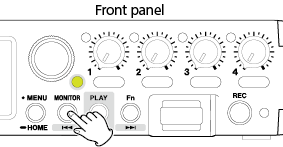
 MONITOR / button
When transport indicator unlit
This opens a menu when the monitoring source can be selected.
When transport indicator lit
This functions as the button.
Pressing the button during playback will return to the beginning of the file. Pressing the button at the beginning of a file will skip to the beginning of the previous file.
Press and hold this button to search backward.
 PLAY (
 /
/ ) button
When stopped
This starts playback. The transport indicator will become lit.
During playback
This pauses playback.
When a file is selected on the Browse Screen
This starts file playback.
 Fn / button
When transport indicator unlit
A specific function can be assigned. (Assigning the Fn button function)
The default setting is MARK/SLATE.
Press it briefly to add a mark or press and hold it to add a slate tone.
When transport indicator lit
This functions as the button.
This skips to the next file.
Press and hold this button to search forward.
 Bluetooth® adapter connector
Connect an AK-BT2 Bluetooth adapter (sold separately) here.
 REC button
Press this when stopped to start recording.
Press and hold this when recording to stop recording.
 REC indicator
This lights during Recording
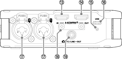
 HDMI® IN port
Connect a DSLR camera or other HDMI® source device here.
 HDMI® OUT port
Connect an HDMI® monitor or other HDMI® sync device here.
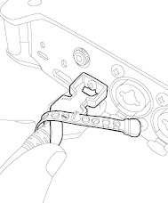
 USB Type-C connector attachment screw hole
Use this to secure a Type-C USB cable with single screw locking.
 USB Type-C port
This is a Type-C USB port.
Computers and smartphones can be connected here. (4-5. Computers and smartphones)
When using an AC adapter, connect it to this port. (Using an AC adapter (sold separately))
 Input jacks 1/2 (Inputs 1/2)
Connect mics with XLR/TRS plugs here.
XLR (1: GND, 2: HOT, 3: COLD)
TRS (Tip: HOT, Ring: COLD, Sleeve: GND)
 HDMI® cable disconnection prevention accessory attachment screws
Attach an accessory using M3 screws here (an ATEN LockPro 2X-EA12 can be used).
Example of installation viewed from behind
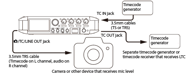
 /TC/LINE OUT jack
Use a 3.5mm stereo mini plug cable to connect this with the line input jack of another device, with a device receiving timecode or with a camera.
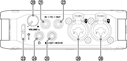

 (headphone) volume knob
Use this to adjust the volume output from the (headphone) jack and for wireless audio monitoring.
 TC IN jack
Use a 3.5mm cable (TS or TRS) to connect this with the timecode output connector of an external device.
 TC OUT jack
Use a 3.5mm cable (TS or TRS) to connect this with a device that receives timecode.
Make timecode output settings in order to use the TC OUT jack. (14-6. Outputting timecode)

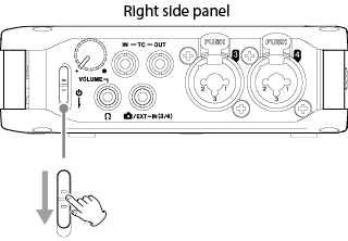
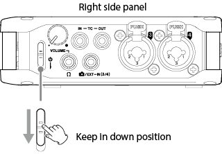
![]() Switch
Switch
Use this to turn the unit on and off.
|
Before turning the unit on, lower the volumes of connected equipment to their minimum levels. Failure to do so might cause sudden loud noises, which could harm hearing or result in other trouble. |
 (headphone) jack
Connect headphones to this jack.

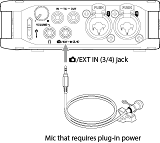
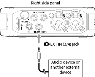
 /EXT IN (3/4) jack
This can be connected to an external mic (3.5mm TRS) that supports plug-in power, a camera or an audio device.
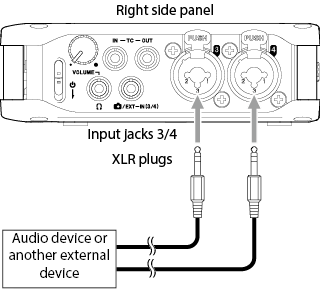
 Input jacks 3/4 (Inputs 3/4)
These balanced analog inputs combine XLR mic and standard TRS jacks.
XLR (1: GND, 2: HOT, 3: COLD)
TRS (Tip: HOT, Ring: COLD, Sleeve: GND)
|
Top panel |
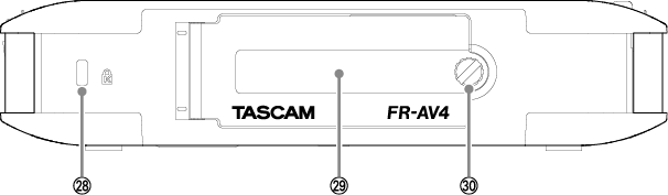
Bottom panel |
|
|
|
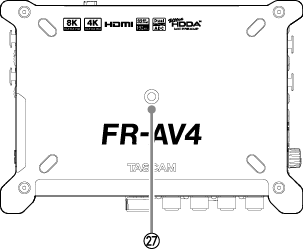
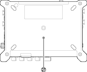
 Tripod mounting threads (1/4-inch)
Use this to attach this unit to a tripod.
|
CAUTION Use screws that are no more than 4.5 mm long. Screws that are longer than 4.5 mm cannot be used for attachment. |
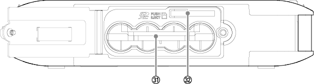
With rear cover open
 Kensington security slot
The unit can be secured by attaching a Kensington lock.
 Rear cover
This covers the battery compartment and the SD slot.
 Rear cover attachment screw
Loosen this to open the rear cover.
 Battery holder
Install batteries in this compartment to power the unit. (Using AA batteries)
 SD card slot
Use this slot to insert SD cards.
Functions can be set and adjusted by using the touchscreen of this unit.
Moreover, most operations can also be conducted using the DATA dial without touching the screen.
1.Press the MENU button.
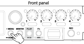
2.Tap the icon for the desired setting item.
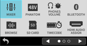
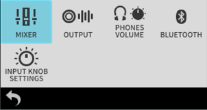
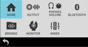
The appearance of the Menu Screen changes according to the status of the unit.
When stopped
When recording
When playing back
NOTE
The Menu Screen has multiple pages. Tap and at the bottom of the screen to move between pages.
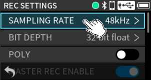
Using the touchscreen
Tap the desired setting item.

Using the DATA dial
1.Turn the DATA dial to highlight the desired item.
2.Press the DATA dial to confirm.
TIP
By pressing the DATA dial while turning it, cursor movement and parameter adjustment can be accelerated.
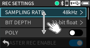
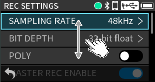
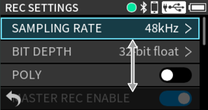
Using the touchscreen
Slide up or down while touching the screen.
Using the DATA dial
Turn the DATA dial to move the selection position.
This will scroll the screen to reveal hidden items.
TIP
By pressing the DATA dial while turning it, cursor movement and parameter adjustment can be accelerated.
Using the touchscreen
Tap the  icon at the bottom left of the screen to go back one screen.
Using the DATA dial
Turn the DATA dial to move the cursor to the mark. Press the DATA dial to go back one screen.
Using the MENU button
Press the MENU button to go back one screen.
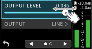
Using the touchscreen
Move a slider left and right to adjust it.
Using the DATA dial
1.Turn the DATA dial to select a slider.
2.Press the DATA dial to select it.
3.Turn the DATA dial to move the slider.
The slider will move linked to the rotation of the DATA dial.
4.Press the DATA dial to confirm.
![]() : On
: On
![]() : Off
: Off
Using the touchscreen
Tap a slider switch to turn it on/off alternately.
Using the DATA dial
1.Turn the DATA dial to select a slider switch.
2.Press the DATA dial to turn it on/off alternately.
The item with the check on its right side is the currently set value.
Tap the screen to select an item.
After confirming the setting, the previous screen will reopen.
Using the DATA dial
1.Turn the DATA dial to select the item to set.
2.Press the DATA dial to confirm.
After confirming the setting, the previous screen will reopen.
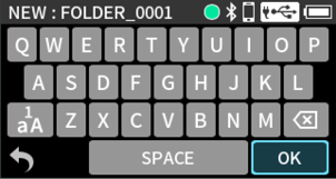
Selecting an item that allows character input will open the Character Input Screen.
The functions of the keys other than the characters are as follows.
![]() : Backspace
: Backspace
![]() : Switch between numbers, lowercase and uppercase letters
: Switch between numbers, lowercase and uppercase letters
![]() : Confirm input
: Confirm input
 : Cancel input and go back
Using the touchscreen
1.Tap keys to input characters.
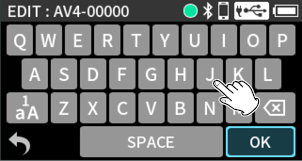
2.Tap the “OK” button to confirm the input.
NOTE
Input characters will be added to the end. Since characters that are not at the end cannot be changed, use the backspace to delete characters and then re-enter them as necessary.
Using the DATA dial
1.Turn the DATA dial to select the desired character for input.
2.Press the DATA dial to confirm.
3.Repeat steps 1 and 2 to input more characters.
4.Select the "OK" button and press the DATA dial to confirm.
Using the touchscreen
1.Tap the area to change.
2.Scroll the selected item up and down to select the value.
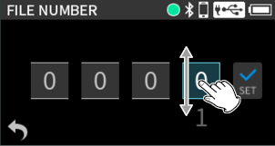
3.Tap the selected value.
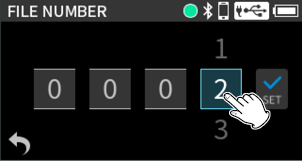
4.Set other digits in the same manner.
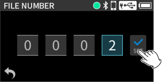
5.When done setting, tap "SET" to confirm.
Using the DATA dial
1.Turn the DATA dial to select the desired number for input.

2.Press the DATA dial to confirm.
3.Turn the DATA dial to change the value.
4.Press the DATA dial to confirm the selected value.
5.Set other digits in the same manner.
6.When done setting, select “SET” and press the DATA dial.
Assigning the Fn button function
The function of the Fn button when pressed can be changed.
Press the MENU button and use PREFERENCES > Fn KEY to set it.
1.Press the MENU button.

2.Tap "PREFERENCES".
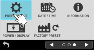
3.Tap “Fn KEY”.
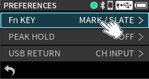
4.Tap the function to assign to the Fn button.
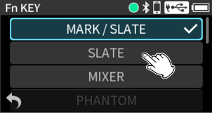
MARK/SLATE (default)
Press it briefly to add a mark or press and hold it to add a slate tone.
SLATE
Press briefly or press and hold to add a slate tone.
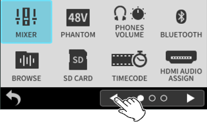
MIXER
This opens the Mixer Screen. (3-8. Mixer Screen)
PHANTOM
This opens the PHANTOM Screen.
PHONES VOLUME
This opens the PHONES VOLUME Screen.
BLUETOOTH
This opens the Bluetooth Screen. (13-2. Installing a Bluetooth® adapter)
BROWSE
This opens the Browse Screen. (9-5. Using the BROWSE Screen)
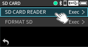
SD CARD
This opens the SD Card Screen. (Setting this unit for use as a card reader)
TIMECODE
This opens the Timecode Screen. (14. Timecode functions)
HDMI
This opens the HDMI AUDIO ASSIGN Screen. (5-7. Outputting audio from this unit using HDMI®)
AUTO MIXER
This opens the AUTO MIXER Screen. (AUTO MIXER function overview)
When set to anything other than MARK/SLATE or SLATE, pressing it briefly will move to that screen. Pressing it when that screen is open will return to the previous screen.
NOTE
Marks will also be placed at positions where slate tones are added.
3-1.Opening and closing the rear cover
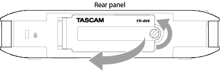
Reverse the opening procedures to close the cover.
Always close the cover before using this unit.
3-2.Inserting and removing SD cards
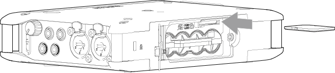
To remove an SD card, press it in gently and then pull it out.
If the cluster size of an SD card is not suitable, the following message will appear on the display. To use the card for recording with this unit, select “YES” to format it.
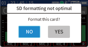
If the cluster size of an SD card is not suitable and recording with this unit is not possible, the following message will appear on the display. In this case, recording with this unit is not possible.
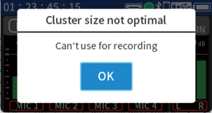
Recording with an SD card or an SDHC card can be made possible by formatting it with this unit.
Recording with an SDXC card in this unit can be made possible by formatting it with a computer, for example, using the following settings.
SDXC cards that are 128 GB or less: exFAT file system and 128-kilobyte cluster size (allocation unit size)
SDXC cards that are more than 128 GB: exFAT file system and 256-kilobyte cluster size (allocation unit size)
3-3.Preparing the power supply
Supply power with one of the following methods when using this unit.
4 AA batteries
AC adapter (TASCAM PS-P520U)
USB cable (USB bus power supply)
NOTE
Alkaline, Ni-MH or lithium AA batteries can be used.
This unit does not have a battery charging function when using an AC adapter.
1.Open the rear cover and remove the battery holder.

2.Install batteries with their and marks as shown in the battery holder. Then, reinstall the case in the unit.
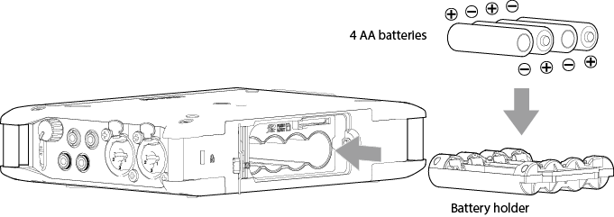
3.Close the back cover and tighten the screw.
NOTE
For operation over a long time, we recommend using a PS-P520U AC adapter (sold separately) or another external power supply.
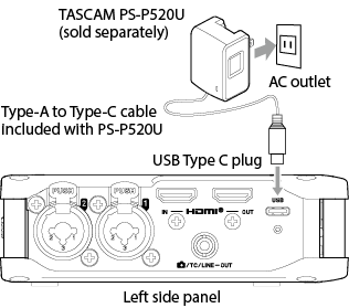
Using an AC adapter (sold separately)
|
CAUTION Noise may occur when recording with a microphone if the unit is too close to the AC adapter. In such a case, keep sufficient distance between the AC adapter and the unit. |
The following pop-up will appear if the unit is unable to determine whether the connected USB power supply has a supply capability of at least 1.5 A.
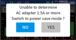
If the connected USB power supply does not have a supply capability of at least 1.5 A, select “YES” and use power save mode. If the connected USB power supply does have a supply capability of at least 1.5 A, select “NO” and use regular mode. (16-11. Power saving (energy conservation) mode)
NOTE
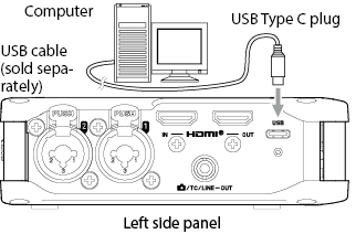
If a computer is going to be used only to supply power, a driver does not need to be installed.
We recommend connecting it to a USB Type-C port on a computer or other device.
3-4.Turning the unit on and off
|
|
|
|
|
|
|
|
|
Release the switch after the start up screen appears. |
|
|
|
|
|
|
|
Release the switch after the POWER OFF screen appears. |
|
CAUTION Always use the If the unit is not able to conduct shutdown procedures properly, recording data, settings and other changes could be lost. Lost data and settings cannot be restored. |
NOTE
The unit cannot be turned off when it is recording.
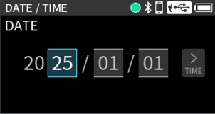
Whenever the date and time have been reset, the DATE/TIME Screen will open.
NOTE
Use the touchscreen or the DATA dial to make settings. See “2-6. Basic operation” for details about setting procedures.
1.Tap the area to change.
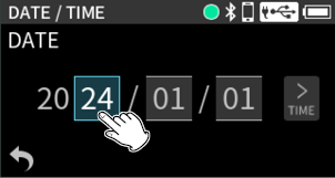
2.Scroll the selected item up and down to select the value.
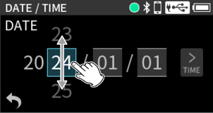
3.Tap the selected value.
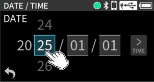
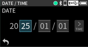
4.Set the month and day in the same manner.
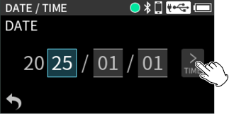
5.Tap “TIME”.
6.Set the hours, minutes and seconds in the same manner.
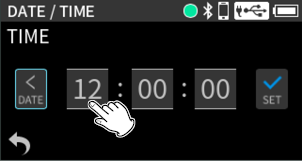
7.When done setting, tap "SET" to confirm.
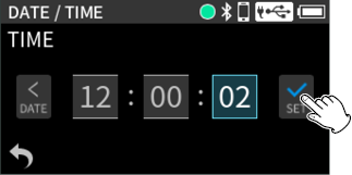
NOTE
Date and time settings can also be changed by using the following setting item.
MENU > DATE/TIME
The unit has a built-in rechargeable battery for retaining date and time settings, so the set date and time will be retained even if no AA batteries are installed in the unit.
This rechargeable battery is charged when the unit power is on.
3-6.Formatting (initializing) SD cards
The following message will appear if an unformatted card is loaded.
Tap the OK button to start formatting.
After formatting completes, the Home Screen will open.
The following setting item can also be used for formatting.
MENU > FORMAT SD
1.Tap “QUICK FORMAT” or “ERASE FORMAT”.

2.Tap the “YES” button.

|
CAUTION Formatting will erase all the data on the SD card. Back up to a computer, for example before formatting a card. |
NOTE
Using the “ERASE FORMAT” option might improve writing performance that has decreased due to repeated use. If “Write Timeout” or “Card slow Check BOF MARK” messages appear during recording, format the card with “ERASE FORMAT”.
ERASE FORMAT takes more time than QUICK FORMAT.
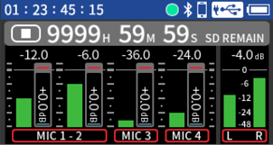
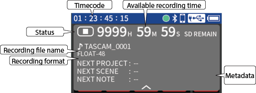
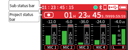
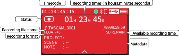
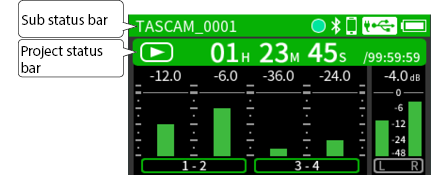
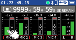
The Home Screen appears after the unit starts up. The composition of the Home Screen changes according to the state.
When stopped
When recording
When stopped, playing, paused or searching forward/backward (using the transport)
Tap the project status bar or press the data dial in any condition to open it and show additional details.
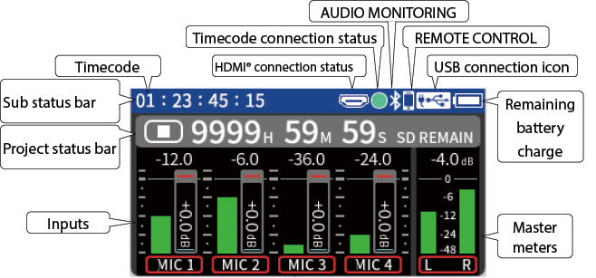
Remaining battery charge
The remaining battery charge is shown when batteries are installed.
|
|
Remaining charge is sufficient |
|
|
Remaining charge becoming low |
|
|
Remaining charge is very low |
|
|
No charge remains (It will also blink in this state.) |
USB connection icon
 : This appears when connected by USB.
 : This appears when powered by USB.
This will blink when the sampling frequency settings of this unit and the USB computer audio interface are not the same.
See “12. USB connection” for details about USB connection settings.
HDMI® connection status
 : This appears when a device is connected to the HDMI® IN port.
 : This appears if the sampling frequencies of this unit and the HDMI® device are different.
The icon will blink if it cannot synchronize with the HDMI® device.
NOTE
If the sampling frequency of the HDMI® device is 48 kHz, 96 kHz or 192k Hz, this unit will synchronize with it.
Project status bar
This shows operation state icons, the time of the recording/playback position and remaining SD card capacity, for example.
|
Status |
Indicator |
|
Stopped |
|
|
Recording |
|
|
Playing |
|
|
Paused |
|
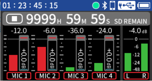
Inputs
This shows input settings and levels.
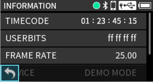
Timecode
This shows the timecode. (14-5. COUNTER VIEW)
Timecode connection status
|
Blinking green* |
|
Receiving timecode and operating with synchronization |
|
Blinking red* |
|
Running by itself based on the last received timecode |
|
Unlit |
|
Not operating with timecode |
* Blinks when connected to AtomX SYNC/UltraSync BLUE
Audio monitoring
This shows the connection status of wireless audio monitoring equipment. (15-1. Wireless audio monitoring)
|
Status |
Indicator |
|
Connected |
|
|
Disconnected |
No indicator |
REMOTE CONTROL
This shows the connection status of remote control devices. (13-3. Connecting with the dedicated control app)
|
BLUETOOTH |
Status |
Indicator |
|
REMOTE CONTROL On |
Not connected |
|
|
Connected |
|
|
|
REMOTE CONTROL Off |
− |
No indicator |
Master meters
This shows mixer master track settings and levels.
Detail display
To close the detail display, tap the  in the bottom middle of the screen or press the DATA dial.
Metadata
This shows the PROJECT, SCENE and NOTE metadata that were set using the remote app and will be used when next recording.
Detail display
To close the detail display, tap the in the bottom middle of the screen or press the DATA dial.
Metadata
This shows the PROJECT, SCENE and NOTE metadata that were set using the remote app and will be used when next recording.
When stopped, playing, paused or searching forward/backward (using the transport)
Detail display
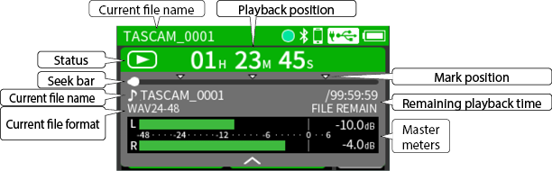
Mark position
If the currently playing file has marks, this shows their positions.
|
Button |
Function |
|
|
Press this when stopped to start playback. Press during playback to pause. |
|
MONITOR / |
Skip to the beginning of the previous audio file Skip to the file beginning (if the playback position is not already there) |
|
Fn / |
Skip to the beginning of the next audio file |
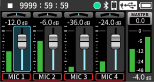
The mix balance of the tracks can be adjusted.
Swipe left on the Home Screen to switch to the Mixer Screen.
|
|
|
|
|
|
NOTE
The Mixer Screen can also be opened by pressing the MENU button and selecting MIXER.
The Mixer Screen cannot be opened when ambisonic mode is on. (16-7. Ambisonic mode)
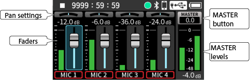
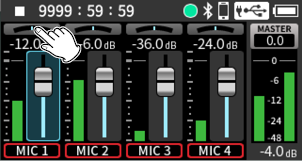
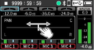
Use these to adjust the left-right volume balance of each track.
|
|
|
Tap the pan setting for the channel to adjust. |
|
|
|
|
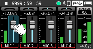
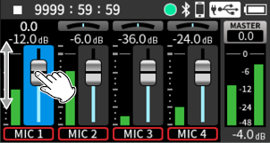
Use these to adjust the output levels of each track.
|
|
|
Tap the fader for the channel to adjust. |
|
|
|
|
Slide the faders to adjust the balance of levels sent to the MASTER.
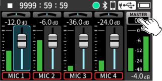
Tap the MASTER button to show master fader and REC ENABLE settings.
|
|
|
Tap the MASTER button. |
|
|
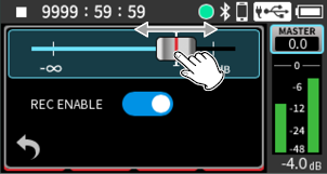
|
|
|
Slide the fader left and right to adjust the level. |
Use this to adjust the level of the mix of all tracks.
After adjusting the balance of the individual track levels, use this when you want to adjust the overall level.
Turn off REC ENABLE to disable recording of the master track.
Panning can be set to the center by double tapping the PAN slider.
Faders can be set to 0 dB by double tapping them.
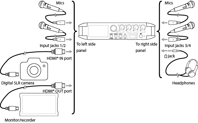
Make input settings according to the connected equipment. See “5-1. Making input settings for each input” for details.
Example connecting to input jacks 1–2
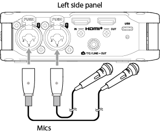
After connecting a mic, press the MENU button and select “MIC” for the INPUT setting. (5-1. Making input settings for each input)
NOTE
Input jacks 3–4 are on the right side. Set them in the same way as necessary.
Make phantom power settings when using a mic that requires phantom power. (Using phantom power)
When TRS plugs are connected to input jacks 1/2 or 3/4, phantom power will not be supplied.
When connecting a device with unbalanced output, use the /EXT/TC IN jack.
Connecting mics that use plug-in power
Connect the mic to the /EXT/IN (3/4) jack.
Stereo and mono mics are supported. Signals connected to the /EXT IN (3/4) jack will be input on input channels 3/4 of this unit.
See “Setting plug-in power” for details about plug-in power settings.
Mid-side mics can be connected to input jacks 1 and 2 or 3 and 4.
Connect the mid-side mic mid to input jack 1 or 3 and the side to input jack 2 or 4.
After connecting the mics, press the MENU button and set MS DECODE/AMBISONICS > MS DECODE to “REC” or “MONITOR”.
See “5-6. Using the mid-side decoding function” for details about recording with mid-side mics.
Connecting ambisonic microphones
These mics can be connected to input jacks 1, 2, 3 and 4.
After connecting the mics, press the MENU button and set MS DECODE/AMBISONICS > AMBISONICS.
See “16-7. Ambisonic mode” for details about recording with ambisonic mics.
When connecting 3.5mm stereo mini cables
Connect it to the /EXT/IN (3/4) jack. Signals connected to the /EXT IN (3/4) jack will be input on input channels 3/4 of this unit.
After connecting, press the MENU button and select “EXT” for the INPUT > INPUT setting. (5-1. Making input settings for each input)
When connecting XLR plugs
Connect them to the 1–4 input jacks.
After connecting, press the MENU button and select “LINE” for the INPUT > INPUT setting. (5-1. Making input settings for each input)
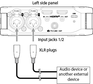
XLR jacks: XLR-3-31 equivalent (1: GND, 2: HOT, 3: COLD)
TRS jacks: 6.3mm (1/4”) standard TRS jacks (Tip: HOT, Ring: COLD, Sleeve: GND)
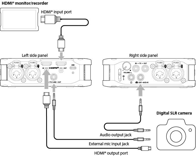
When recording video with a camera, the same sound can be recorded simultaneously by the camera and this unit. In order to output sound to a camera, connect it with this device as shown below.
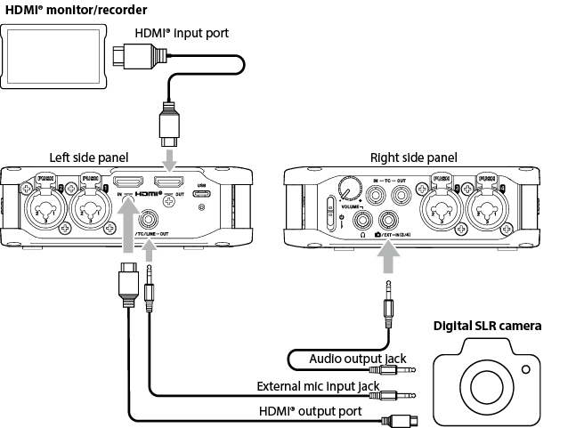
Recording audio from this unit on a camera
Use a commercially-available 3.5mm stereo mini plug cable to connect the /TC/LINE OUT jack on the left side of this unit with the external mic input on the camera.
Connecting with a camera using HDMI®
This unit can be synchronized with a camera's clock by connecting the camera's HDMI® output to this unit's HDMI® IN port. Moreover, HDMI® timecode can be received from a camera.
Connecting HDMI® monitors/recorders
Video input from the camera by HDMI® can have audio recorded by this unit added to it and then be output from the HDMI® OUT port. The received HDMI® timecode can also be output.
NOTE
Refer to the camera’s operation manual to identify this connector on the camera.
To mount a camera on this unit, use the camera attachment screw on the top of the unit.
The line output level can be attenuated up to 80 dB for camera use.
See “11-1. Setting output for camera use” for details.
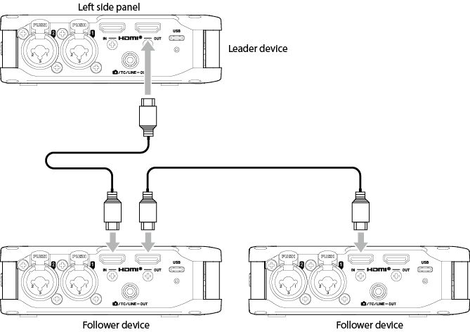
Cascade operation of multiple FR-AV4 units possible by connecting them with HDMI® cables.
Cascade operation has the following benefits.
Recording/stopping operations on the leader FR-AV4 can be executed simultaneously on follower devices.
Even over long periods of recording, time, lags will not occur between audio files thanks to digital clock synchronization.
Sharing timecode using HDMI® connection makes aligning recorded audio files easy.
Since audio can also be output through HDMI® connections, audio monitoring from the last follower unit is possible without reconnecting headphones.
TIP
A camera with HDMI® output can also be used as the leader device in cascade connection.
NOTE
Set follower devices to synchronize with HDMI® timecode. (Receiving timecode by HDMI®)
To monitor audio using the last follower device, set the preceding devices in the cascade connection to output HDMI®. (5-7. Outputting audio from this unit using HDMI®)
When using an external monitoring system to listen
Connect the external monitoring system (powered monitor speakers or an amplifier and speakers) to the /TC/LINE OUT jack.
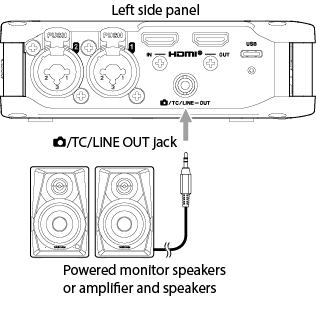
NOTE
When outputting audio from the LINE OUT, turn off timecode output from the LINE OUT jack. See “14-6. Outputting timecode” for details.
When using headphones to listen
Connect headphones to the (headphone) jack.
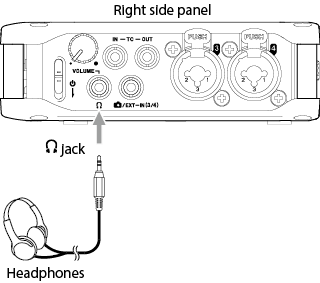
Press the MENU button to open OUTPUT and make settings according to the connected equipment.
|
While wearing headphones, do not connect or disconnect them or turn the unit on or off. Doing so might cause sudden loud noises, which could harm hearing. Before putting headphones on, always lower the volume to the minimum (turn all the way counterclockwise). |
Adjusting the headphone output volume
Use the volume knob on the right side to adjust the volume output from the (headphone) jack and for wireless audio monitoring.
To select the output that is adjusted by the volume knob, see “5-4. Output settings”.
Press the MENU button and check PHONES VOLUME to see the current volume settings.
The following uses are possible when connected by USB to a computer (Windows/Mac) or smartphone.
Use a mic connected to this unit as a USB mic.
Simultaneously record on a computer while recording on the SD card in the unit (backup recording)
Monitor sound from the computer
Use as an SD card reader (only when connected to a computer)
NOTE
When connecting this unit with an iOS device, set it to use batteries. See “16-8. Selecting the power source” for details.
A USB cable must be prepared to connect this unit to a computer (Windows/Mac) or smartphone. (USB cables (for communication and data transmission))
Connecting to a computer using a USB cable
4-6.Connecting to a timecode transmitting device
See “14. Timecode functions” for details about use.
Use a 3.5mm cable (TS or TRS) to connect the output of the timecode transmitting device to the TC IN connector on this unit.
Press the MENU button and set TIMECODE > MASTER to “TC IN”. See “Receiving timecode through the TC IN jack” for details.
Timecode synchronization is also possible using Bluetooth transmission. See “13-2. Installing a Bluetooth® adapter” for details.
This unit can also be used as a timecode generator.
Make timecode output settings in order to transmit timecode. See “14-6. Outputting timecode” for details.
1. Using HDMI® timecode
2. Using a timecode generator
Input timecode from an external timecode generator through the TC IN jack. By using jam sync, devices that are synchronized to timecode can also be added.
3. Using Atomos UltraSync BLUE
An AK-BT2, which is sold separately, is necessary.
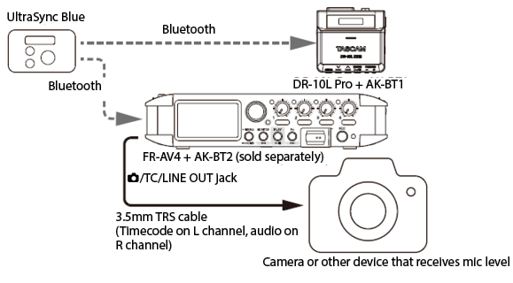
TIP
After once synchronizing with timecode from an Atomos UltraSync Blue or a timecode generator, along with ordinary connection, it is possible to make it jam sync even if it becomes disconnected by setting it to FREE RUN.
The FR-AV4 can become a timecode generator and provide timecode to a camera. (14. Timecode functions)
5-1.Making input settings for each input
Follow one of the procedures below to open the Input Settings Screen.
When the Home Screen is open, press the 1, 2, 3 or 4 button on the unit.

Tap the desired track when the Home Screen is open.
The Input Settings Screen has multiple pages.
Tap the arrows ( / ) at the bottom of the screen to move between pages.
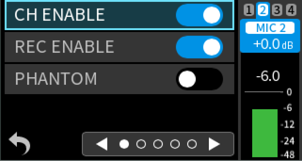
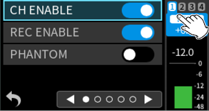
Set this using CH ENABLE.
Channels can be enabled (on) or disabled (off).
Options: Off, On (default)
NOTE
REC ENABLE will also be set linked with CH ENABLE.
If you want to include the channel sound in the mix, but you do not want to record the channel itself, turn off REC ENABLE only.
When CH ENABLE is OFF, that channel will appear gray on the Home Screen.
Set this using REC ENABLE.
Channels can be enabled (on) or disabled (off) for recording.

Options: Off, On (default)
Set this using INPUT.
The input sources of channels can be set.
When using input jacks 1–4, select “MIC” or “LINE”.
When using /EXT IN (3/4), select “EXT”.
When using computer output as audio input to this unit, select “USB”.
When not stereo linked
MIC (default), LINE, EXT, USB
When stereo linked
MIC (default), LINE, EXT (ST), EXT (MONO), USB
When “LINE” is selected, the input signal is attenuated 20 dB.
“EXT” can only be selected for channels 3 and 4.
NOTE
If MS DECODE or AMBISONICS is enabled, this setting is fixed to “MIC”.
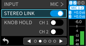
Set this using STEREO LINK.
Audio from channels 1–2 and 3–4 can be recorded as stereo audio files.
Options: Off (default), On
When STEREO LINK is turned on, the following settings for the odd channel will be applied to the even channel.
INPUT, DELAY, LOW CUT, LIMITER, EQ, NOISE GATE
Appearance when STEREO LINK is on for inputs 1-2
|
Home Screen when stopped |
|
|
|
Input Screen |
|
|
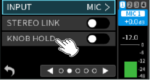
Set this using KNOB HOLD.
Operation of the 1–4 knobs can be disabled if you do not want input levels to be changed.
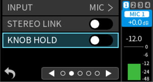
Off (default)
1–4 knobs are enabled
On
1–4 knobs are disabled
TIP
Press and hold the 1–4 buttons to switch the KNOB HOLD setting.
Set this using PHANTOM.
Make this setting when using mics that require phantom power.
See “Setting the phantom power voltage” for details about phantom power voltage settings.
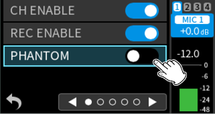
Options: Off (default), On
Turn on phantom power only when using condenser mics that require phantom power. Turning on phantom power when a dynamic mic or other external device that does not require it is connected could damage this unit and the connected equipment.
Supplying phantom power to some ribbon mics could break them. If in doubt, never supply phantom power to a ribbon mic.
|
CAUTION
Furthermore, when using an adapter that does not meet the recommended specifications, supplying phantom power to multiple inputs could cause the power to turn off automatically due to insufficient current.
|
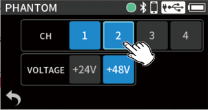
Checking and setting phantom power
Press the MENU button and select PHANTOM to show the PHANTOM setting status for all inputs and enable changing them.
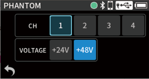
Phantom power can be turned on for each input by selecting it.
Setting the phantom power voltage
Options: +24V, +48V (default)
Select this according to the specifications of the mic.
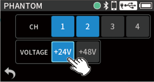
|
CAUTION Some condenser microphones will not operate when phantom power is set to “+24V”. |
Set this using PLUG IN POWER.
Options: OFF (default), 2.5V, 5V
When connecting a mic that requires plug-in power, set this to “2.5V” or “5V” according to the specifications of that mic.
|
CAUTION Do not turn plug-in power on unless a plug-in power mic is connected. Other connected equipment could be damaged by it. See the mic operation manual for details. |
NOTE
This setting is only valid when the input source setting is “EXT”.
Compensating for delay between different mic distances
Set this using DELAY.
Use this function to compensate for delays that result from differences in distances between connected mics.
Options: 0 (default) – 300 ms
NOTE
This cannot be used when the sampling frequency is set to 192 kHz.
Set this using LOW CUT.
This cuts audio below the selected frequency.
The low-cut filter can reduce bothersome noise, such as from wind, air-conditioners and projectors.
Set the cutoff frequency of the low-cut filter to match the noise.
Options: OFF (default), 40 Hz, 80 Hz, 120 Hz, 220 Hz
NOTE
This cannot be used when the sampling frequency is set to 192 kHz.
Set this using LIMITER.
Using the limiter can suppress distortion caused by sudden excessive sound input.
Off (default)
The limiter function is disabled.
On
This function prevents distortion when signals that are too loud are input suddenly.
This is suited for recording live performances and other situations with large volume changes.
|
CAUTION Distortion could occur when the input sound is excessively loud even if the limiter function is on. In such cases, lower the input level or increase the distance between the unit and the sound source. |
NOTE
This cannot be used when the sampling frequency is set to 192 kHz.
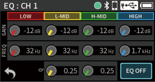
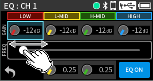
Set this using EQ.
The equalizer has the effect of amplifying and attenuating specific frequency ranges. This can be used, for example, to enhance the sound of individual instruments, to adjust the balance of a wide frequency range and to cut specific unwanted frequencies.
OFF (default)
This disables the equalizer.
ON
With this setting, four bands can be adjusted manually. In addition to low-frequency and high-frequency boosts, two peak curves can be set.
Gain knobs (HIGH, H-MID (high mid), L-MID (low mid), LOW)
These set the amounts levels are increased or decreased for each band.
Ranges
GAIN: −12 dB – +12 dB (0 dB default)
FREQ knobs (HIGH, H-MID (high mid), L-MID (low mid), LOW)
These set the cutoff frequencies of the HIGH and LOW bands and the middle frequencies of the H-MID and L-MID bands.
Ranges
HIGH: 1.7 kHz – 18.0 kHz (8 kHz default)
H-MID: 32 Hz – 18.0 kHz (4 kHz default)
L-MID: 32 Hz – 18.0 kHz (300 Hz default)
LOW: 32 Hz – 1.6 kHz (150 Hz default)
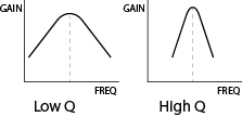
Q knobs (H-MID (high mid), L-MID (low mid))
These set the acuteness of these bands.
The higher the value is the more acute it becomes, making it affect a narrower frequency band around the set frequency. The lower the value is the less acute it becomes, making it affect a broader frequency band around the set frequency.
Ranges
H-MID: 0.25 – 16.00 (default 1.00)
L-MID: 0.25 – 16.00 (default 1.00)
NOTE
This cannot be used when the sampling frequency is set to 192 kHz.
1.Tap the knob to be adjusted.
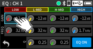
2.Adjust with the slider.
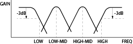
Examples of EQ characteristics
Set this using NOISE GATE.
Sound below a set level can be muted.
When “LOW” is selected, only quiet sounds will be muted. When “HIGH” is selected, sounds up to a certain level will also be muted.
Options: OFF (default), LOW, MID, HIGH
NOTE
This cannot be used when the sampling frequency is set to 192 kHz.
Set this using PHASE INVERT.
Turning this on will invert the phase.
Options: Off (default), On
TIP
If the sound seems to be unclear when recording the same source with more than two or more mics, inverting the phase of one or more inputs could improve the sound quality.
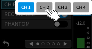
Changing the channel being set on the Input Setting Screen
1.Tap the input channel shown at the top right of the screen.
2.Tap the channel to set.
|
|
|
|
|
|
5-2.Saving and recalling input settings
The following input settings can be saved and recalled.
- DELAY
- LOW CUT
- LIMITER
- EQ
- NOISE GATE
A maximum of 5 presets can be saved.
NOTE
Before saving and when the FACTORY PRESET is loaded, they will be set to their default values.
1.When the Home Screen is open, press the button for the desired channel (1–4) for saving.
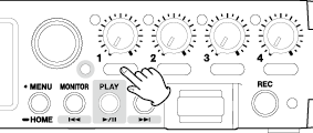
2.Tap “SAVE”.
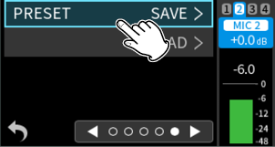
3.Tap the preset to save.

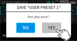
4.When a confirmation pop-up opens, tap “YES”.
5.Tap  at the bottom left of the screen to return to the Home Screen.
1.When the Home Screen is open, press the button for the desired channel (1–4) for recalling.

2.Tap “PRESET LOAD”.
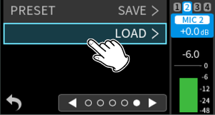
3.Tap the desired preset to recall.
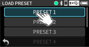
This will load the preset.
4.Tap at the bottom left of the screen to return to the Home Screen.
Turn the input level adjustment knobs to adjust the audio signal levels recorded in recording files.
While watching the level meters, adjust the input level adjustment knobs so that levels average around −12 dB and the peak indicators do not light.
Recording sounds might distort when peak indicators light.
NOTE
If a knob’s position is different from its level setting value, the knob will function after it is moved to the position of the set value.
If a input level exceeds −2 dB, that peak indicator on the unit will light.
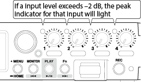
If an overload occurs with an analog circuit, the entire level meter will become red.
Since this could cause the recorded audio to become distorted, make the following adjustments.
Distance the mic from the sound source.
Lower the volume of the sound source.
Selecting the headphone volume knob function
Press the MENU button and open PHONES VOLUME.
 : On
: On
 : Off
: Off
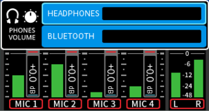
HEADPHONES
When this is on, the headphone volume knob can adjust the headphone output volume.
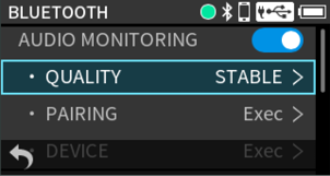
BLUETOOTH
When this is on, the headphone volume knob can adjust the Bluetooth audio monitoring output volume.
NOTE
When both HEADPHONES and BLUETOOTH are turned on, both of their volumes can be changed while maintaining two volume balances.
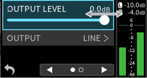
Set this by pressing the MENU button and using OUTPUT > OUTPUT.
Set this to adjust the volume output from the /TC/LINE OUT jack. (11-1. Setting output for camera use)
Set this by pressing the MENU button and using OUTPUT > OUTPUT LEVEL.
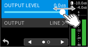
Range: −60 – 0 dB (default)
Set this by pressing the MENU button and using OUTPUT > LIMITER.
This function prevents distortion when signals that are too loud are output suddenly.
Options: Off (default), On
|
CAUTION Distortion could occur if the output sound is excessively loud even when the limiter function is on. In such a case, lower the output level manually. |
NOTE
This cannot be used when the sampling frequency is set to 192 kHz.
Set this by pressing the MENU button and using OUTPUT > DELAY.
The amount of delay time to the output device can be adjusted.
This function is convenient for adjusting video and audio on a connected camera.
Options: Off (default) – 300 ms
NOTE
This cannot be used when the sampling frequency is set to 192 kHz.
To change other settings, press the MENU button and open INPUT KNOB SETTINGS.
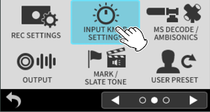
Setting the GANG operation mode
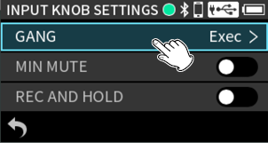
Set this by pressing the MENU button and using INPUT KNOB SETTINGS > GANG.
Setting the GANG operation mode links the input levels of channels 1–4 so they can be operated simultaneously. Knobs can be ganged in 2 groups.
1.Select “GANG”.
2.Tap channels to assign them to a gang group.
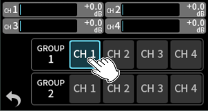
The same channel cannot be assigned to both group 1 and group 2.
NOTE
Even if a ganged channel reaches its upper or lower limit first, operation of the current channel can continue. In this case, differences in levels are remembered by the unit. When operation of a channel is reversed, level differences will be retained when operated.
When gang settings are enabled, gang states can also be checked on the Home Screen.
Setting input level operation mute
Set this by pressing the MENU button and using INPUT KNOB SETTINGS > MIN MUTE.
Whether or not minimizing the 1–4 knobs mutes their inputs can be set.
Set this using the “MIN MUTE” item.
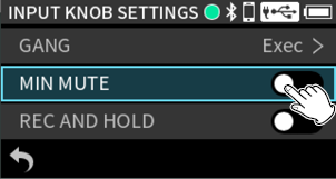
Off (default)
Minimizing the 1–4 knobs does not mute their inputs.
On
Minimizing the 1–4 knobs mutes their inputs.
Fixing input levels while recording
Set this by pressing the MENU button and using INPUT KNOB SETTINGS > REC AND HOLD.
Operation of the 1–4 knobs can be disabled in coordination with recording.
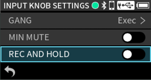
Off (default)
1–4 knobs are enabled
On
Starting recording will disable operation of the 1–4 knobs.
NOTE
Use the KNOB HOLD function to fix input levels for individual channels. (Locking input levels)
5-6.Using the mid-side decoding function
Mid-side mics can be used for recording, and their recordings played back.
See “Connecting mid-side mics” for details about connecting mid-side mics.
Set the jacks connected to the mid-side mics by pressing the MENU button and using MS DECODE/AMBISONICS.
1.Tap the channel to set.
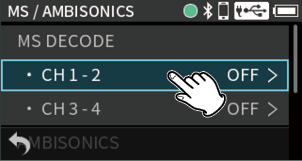
2.Tap the mode to set.
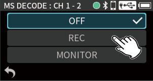
OFF (default)
Recording will occur in ordinary mode without using mid-side decoding.
REC
This mode decodes while recording. Playback is conducted without decoding.
MONITOR
Record mid-side mic output without decoding for decoding later. Use this mode to monitor when recording with mid-side mics.
Use this also when playing back mid-side files that were recorded without decoding.
NOTE
The mid-side decoding function can be used when inputting mid-side mics through the 1/2 or 3/4 input jacks and when using this unit to play imported files recorded using mid-side mics. Turn off the mid-side decoding function to not use it.
While MS DECODE is on, stereo-linking for those channels will be turned on and their input sources set to MIC. These settings cannot be changed while it is on.
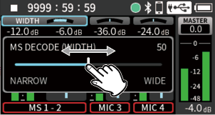
Use the Mixer Screen to adjust the mid and side levels.
1.Tap the MS balance area.
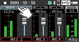
2.Slide the slider to adjust the width of the sound.
5-7.Outputting audio from this unit using HDMI®
Audio from this unit can replace the HDMI® output audio. HDMI® audio has 8 channels. 2 channels at a time can be replaced with audio from this unit.
Press the MENU button and use HDMI AUDIO ASSIGN to set this.
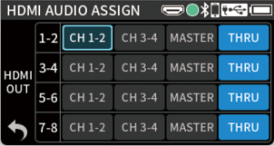
HDMI OUT 1-2
Select the audio from this unit to replace HDMI® audio channels 1–2.
Options: CH 1–2, CH 3–4, MASTER, THRU (default)
HDMI OUT 3–4
Select the audio from this unit to replace HDMI® audio channels 3–4.
Options: CH 1–2, CH 3–4, MASTER, THRU (default)
HDMI OUT 5–6
Select the audio from this unit to replace HDMI® audio channels 5–6.
Options: CH 1–2, CH 3–4, MASTER, THRU (default)
HDMI OUT 7–8
Select the audio from this unit to replace HDMI® audio channels 7–8.
Options: CH 1–2, CH 3–4, MASTER, THRU (default)
NOTE
When set to “THRU”, HDMI® input audio for that channel will be output as is.
Settings other than THRU cannot overlap.
If the sampling frequencies of this unit and the HDMI® device are different, THRU will be set automatically.
|
|
|
Press the REC button. |
|
|
|
|
|
Recording |
|
|
|
Press and hold the REC button until recording stops. |
|
|
|
|
|
|
|
|
Stopped |
Every input sound can be monitored using headphones, for example.
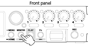
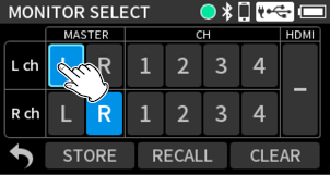
1.Press the MONITOR button to open the MONITOR SELECT Screen.
2.Tap channels to enable them for monitoring.
Select the desired monitoring sources for the L and R channels.
A mix of the sounds will be monitored if multiple sources are selected.
 : Monitoring off
 : Monitoring on
Off (nothing selected)
The monitoring sound will be muted.
MASTER L
The sound of the mixer L channel will be monitored.
MASTER R
The sound of the mixer R channel will be monitored.
CH 1–4
The input sounds of the tracks will be monitored.
3.To monitor HDMI® input, tap the HDMI area at the right of the screen.
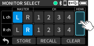
4.Tap the channels to monitor.
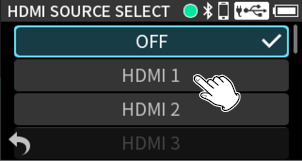
HDMI 1–8
Monitor the sounds of HDMI® input channels.
HDMI 1–2, HDMI 3–4, HDMI 5–6, HDMI 7–8
Monitor the sounds of HDMI® input channels as stereo pairs.
NOTE
If the sampling frequencies of this unit and the other HDMI® device are different, the monitoring sound will be silent.
5.Tap at the bottom left of the screen to return to the Home Screen.
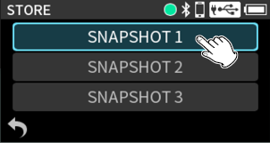
A maximum of 3 snapshots can be saved.
1.Tap “STORE”.
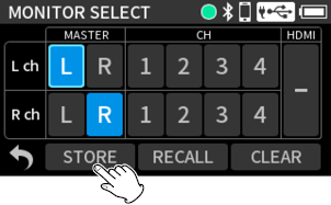
2.Tap the snapshot to save.
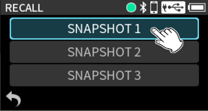
1.Tap “RECALL”.
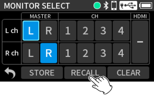
2.Tap the snapshot to recall.
Initializing monitoring settings
Tap “CLEAR”.
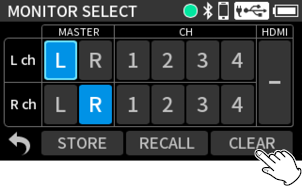
This will restore the monitoring settings to their default values.
L channel: MASTER L
R channel: MASTER R
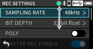
7-2.Changing the recording file format
Set this by pressing the MENU button and using REC SETTINGS.
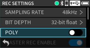
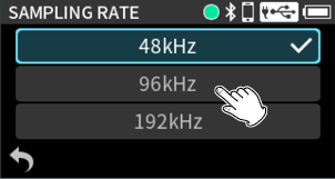
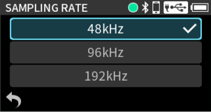
SAMPLING RATE
Select the sampling frequency.
Options: 48kHz(default), 96kHz, 192kHz
BIT DEPTH
Select the quantization bit depth.
Options: 24-bit, 32-bit float (default)
|
32-bit float This unit supports 32-bit float recording. Files recorded using 32-bit float have the following advantages when being edited afterward.
CAUTION Analog clipping will not be changed when volume is lowered. |
POLY
Off (default)
Mono or stereo files will be recorded for each channel according to their stereo link settings.
On
Channels 1–4 and a MIX will all be recorded as a single file.
REC ENABLE cannot be turned off for any channel.
Off
MIX files will not be recorded.
On (default)
MIX files will be recorded.
Simultaneous recording of mix files in WAV and MP3 formats (dual format function)
Set this by pressing the MENU button and using REC SETTINGS > DUAL FORMAT.
Off (default)
MP3 format mix files will not be created.
On
In addition to WAV files, MP3 format mix files will be created.
NOTE
To record using DUAL FORMAT, set MASTER REC ENABLE to ON.
7-3.Capturing sound before recording starts
Set this by pressing the MENU button and using REC SETTINGS > PRE REC.
When this is on, up to 7 seconds of signal input can be captured before the start of recording.
Options: Off (default), On
NOTE
When REC FORMAT is set to 96kHz, signals can be captured for a maximum of 5 seconds before recording starts. When set to 192kHz, signals can be captured for a maximum of 2 seconds.
If a menu is used or playback operations are conducted, capturing pre-recorded audio will restart from that moment.
See “9-1. File name overview” for details.
7-5.Designating the folder used for recordings
See “9-8. Setting where recording projects are saved” for details.
|
|
|
Press the |
|
|
|
|
|
Current project during playback The transport indicator will light, The |
|
|
|
Press the |
|
|
|
|
|
Stopped |
|
|
|
Press the MENU button and select HOME. Or, press and hold the MENU button. |
|
|
|
|
|
The transport indicator will become unlit, and the Home Screen will reopen. |
TIP
The Home Screen can also be reopened by pressing and holding the PLAY button.
Returning to the Home Screen will automatically stop playback.
See “When stopped, playing, paused or searching forward/backward (using the transport)”.
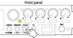
8-4.Starting and pausing playback
When stopped or paused, press the / button to start playback.
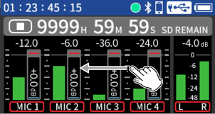
8-5.Changing the playback position
Slide the seek bar when playing or paused or stopped.
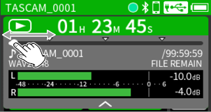
The playback position can also be changed by turning the data dial.
NOTE
Tap the project status bar or press the data dial to show the seek bar.
8-6.Selecting files for playback
When the Transport indicator is lit, use the and buttons to select the file for playback.
Pressing the button during playback will return to the beginning of the file. Pressing the button at the beginning of a file will skip to the beginning of the previous file.
Pressing the button when located at the beginning or middle of a file will skip to the beginning of the next file.
By pressing the MENU button and setting the MARK/SLATE TONE > MARK > SKIP MODE item, the button can be used to move to the previous mark and the button can be used to move to the next mark.
8-7.Searching backward and forward
Press the or button on the unit to search backward or forward while pressing.
This unit can record and play wav (including BWF) files.
Files recorded by this unit are named as described below.

Characters set by user
When the type is set to DATE
YYMMDD (YY: year, MM: month, DD: date)
The last two digits of the year are used, and two digits each are used for the month and day.
When the type is set to TEXT
A string of 1–9 characters can be specified as desired.
The default value is “AV4-00000”.
The usable characters are as follows.
Uppercase and lowercase alphabet letters numerals 0–9,
and the following symbols:
! # $ % & ' ( ) + , - . ; = @ [ ] ^ _ ` { } ~ (space)
File numbers
This shows the order recorded.
The default value is “0001”.
MP3 files recorded using dual format
File number+M
Channel number
This shows which channel was recorded.
When stereo-linking off
Channel number 1, 2, 3 or 4
When stereo-linking on
Linked channel number 1_2 or 3_4
Master files
MIX
When 6CH POLY setting is on
1_6
Project name
This is the characters set by the user and the file number connected by an underscore (_).
Since the file number is increased each time a file is recorded, the project also changes with each recording. See “9-3. Project overview” for details about projects.
NOTE
If a file with the same user-set characters and file number already exists at the time of recording, “[---]” will be added after the file number. (--- is a three-digit number, starting with “001”.)
Example: YYMMDD_0001[001]-1.wav
Files recorded in ambisonic mode will be named as follows.
When recorded with A format
TASCAM_AmbiA_0001-1.wav
When recorded with B Format FuMa
TASCAM_FuMaB_0001-1.wav
When recorded with B Format AmbiX
TASCAM_ambiXB_0001-1.wav
Set this by pressing the MENU button and using REC SETTINGS.
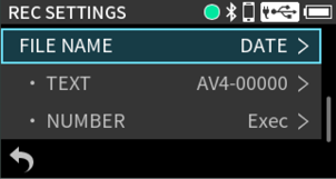
FILE NAME
Set the characters used at the beginning of the file name.
DATE (default)
The DATE is added to the file name.
YYMMDD (YY: year, MM: month, DD: date)
The last two digits of the year are used, and two digits each are used for the month and day.
TEXT
The 1–9 characters set freely using TEXT are added to the file name.
The default value is “AV4-00000”.
UNIT NAME
The name of the individual device is used for the file name.
NOTE
If DATE is selected, the file name will be created using the date and time of the unit’s internal clock. Set the clock in advance to enable recording with the correct date.
The dedicated control app can be set to automatically set the clock of the unit when it is connected to the app.
The UNIT NAME must be set in advance using the dedicated control app. See the manual for the dedicated control app for setting procedures.
If the UNIT NAME has not been set, “FR-AV4” will be used for file names.
Setting characters to use for file names
Set this using “TEXT”.
See “Character input” for details about character input.
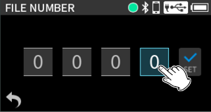
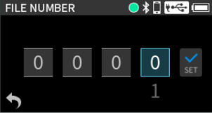
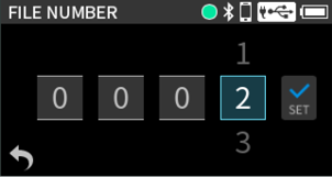
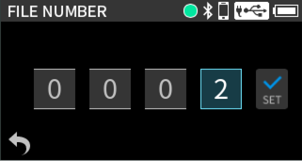
Set this using the “NUMBER” item.
Tap the numbers on the screen to change them. When done setting, tap "SET" to confirm.
See “Inputting numbers” for details about number input.
NOTE
If a file with the same name and number already exists at the time of recording, “[---]” will be added after the file number. (--- is a three-digit number from 001 to 999.)
This will be disabled if the METADATA function has been turned on using the dedicated control app.
9-2.File and project structure overview
Formatting SD cards with this unit will create SOUND and UTILITY folders.
Folders can be created inside the SOUND folder.
Create them as necessary. (Creating folders)
After the SD card is formatted, recording data is saved in the SOUND folder.
To change the folder where data is saved, select the folder on the BROWSE Screen, and select OPEN. (9-8. Setting where recording projects are saved)
Files created during a single recording are referred to as a project.
Files belong to the same project if their names are the same from the characters set by the user through the file numbers. See “9-1. File name overview” for details about project names. The way project names are given can be changed in the same manner as for file names. (Changing how files are named)
Example
|
Project name |
Files in the same project |
|
TASCAM_0001 |
TASCAM_0001-1.WAV |
|
TASCAM_0001-2.WAV |
|
|
TASCAM_0002 |
TASCAM_0002-1_2.WAV |
Individual files not created by this unit and loaded from a computer or other source are each treated as a single project.
This illustration is an example of the folder hierarchy on an SD card used with this unit.
|
¥ (root folder) |
||||||||
|
SOUND |
||||||||
|
FOLDER_0000 |
||||||||
|
FOLDER_0001 |
||||||||
|
TASCAM_0001-1.WAV |
||||||||
|
... |
||||||||
|
... |
||||||||
|
... |
||||||||
|
TASCAM_0002-1.WAV |
||||||||
|
... |
||||||||
|
... |
||||||||
|
... |
||||||||
|
FOLDER_0002 |
||||||||
|
... |
||||||||
|
... |
||||||||
|
... |
||||||||
|
TASCAM_0003-1.WAV |
||||||||
|
... |
||||||||
|
... |
||||||||
|
... |
||||||||
|
FOLDER_0003 |
||||||||
|
... |
||||||||
|
... |
||||||||
|
... |
||||||||
|
UTILITY |
||||||||
|
Firmware update files |
||||||||
SOUND and UTILITY folders will be created automatically during formatting.
Only two levels of subfolders can be created.
This unit cannot recognize subfolders and files beyond three levels.
The maximum total number of files and folders is 1000.
Everything in the SOUND folder and its subfolders is shown on the BROWSE Screen.
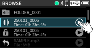
Files on the loaded SD card can be worked with and easily played back. Press the MENU button and show BROWSE.
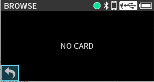
NOTE
If an SD card is not loaded, the following screen will appear.
Tap at the bottom left of the screen to return to the Home Screen. Then, install an SD card.
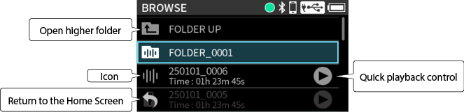
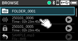
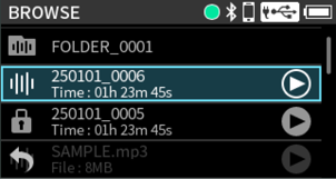
Icon
Files that can be played are shown with a waveform icon. Folders are shown with  .
.
Folder/file name
Tap this to open the folder menu or file menu.
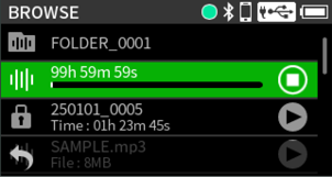
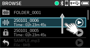
Quick playback control
Tap  to start playback, and tap
  to stop playback.
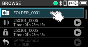
1.Tap the desired destination folder.
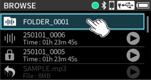
2.Tap “OPEN”.
To move up a folder level, select “FOLDER UP”.
Tap the quick playback control button for the file to be played.
|
|
|
|
|
|
Tap to stop playback.
Tap the desired folder.
|
|
|
|
|
|
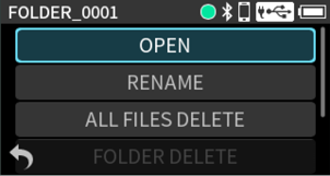
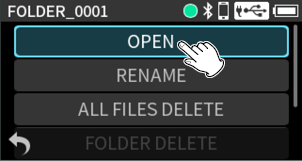
OPEN
This shows the contents of the folder.
RENAME
This opens a screen where the folder name can be edited.
Folder names that can be changed can have between 1 and 11 characters. See “Character input” for how to input characters.
ALL FILES DELETE
This deletes all projects and files inside the folder. Folders, however, will not be deleted.
FOLDER DELETE
This deletes the folder.
Folders that have files remaining in them cannot be deleted. Delete all the files in the folder before deleting the folder.
NOTE
The folder that was last selected using “OPEN” or “FOLDER UP” is where the next recording file will be saved.
1.Scroll to the very bottom of the screen.
2.Tap “NEW FOLDER”.
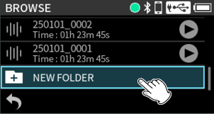
3.Input the folder name.
See “Character input” for how to input characters.
If a folder named FOLDER+number already exists, selecting and tapping “NEW FOLDER” will show FOLDER+ (the number+1) as the default value. If you want to change this name, use the RENAME function.
9-7.File and project operations
Tap the desired file.
|
|
|
|
|
|
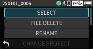
SELECT
Selecting a file makes it the current project and reopens the Home Screen.
Press the button on the unit to play the current project.
FILE DELETE
This deletes the file.
Protected (read only) files cannot be deleted.
RENAME
Use this to change the project name.
Only projects that have been recorded by this unit can be changed. The number of characters can be changed to between 1 and 9.
See “Character input” for how to input characters.
CHANGE PROTECT
Use this to activate/deactivate the protection of files in the project.
Lock marks (![]() ) are shown for icons of files that are protected.
) are shown for icons of files that are protected.
FILE INFORMATION
This shows information about files in the project.
This shows the project name, recording format, recording date, playback time and file size.
This shows the PROJECT, SCENE and NOTE data recorded in iXML and the timecode setting.
MARK
This opens a list of the marks.
The name of the file shown in the project status bar is the current project. Conducting recording or playback will switch the current project.
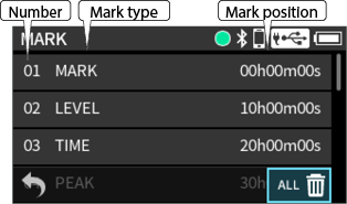
See “10. Mark functions” for information about mark types.
Tap ![]() on the MARK list screen shown above to delete all marks.
on the MARK list screen shown above to delete all marks.
9-8.Setting where recording projects are saved
Follow the procedures below to make the selected folder the save destination.
1.Tap the folder to be made the save destination.

2.Tap “OPEN”.

NOTE
To set the folder above as the save destination, select “FOLDER UP”.
The types of marks and conditions when they are added are as follows.
MANUAL
Marks added manually
TIME
Marks added when set time elapses
PEAK
Marks added when input signal exceeds peak level
BUFFER OVERFLOW (BOF)
Marks added when SD card write errors occur during recording
Press the MENU button and open MARK/SLATE TONE.
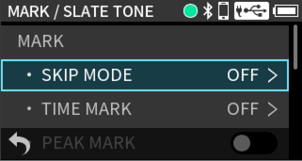
To manually add marks, set the Fn button function to MARK/SLATE. (Assigning the Fn button function)
Adding marks at regular intervals
Set this using TIME MARK.
Marks will be added automatically when the set time elapses during recording.
Options: OFF (default), 5 min, 10 min, 15 min, 30 min, 60 min
Adding marks when peak levels occur
Set this by pressing the MENU button and using MARK/SLATE TONE > PEAK MARK.
When this is on, marks will be added automatically when input signals exceed the peak level during recording. These marks can be used after recording to find parts where the peak level was exceeded.
Options: Off (default), On
When recording, press Fn (MARK/SLATE) button to add a mark at any point.
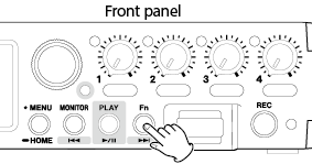
When a mark is added, a pop-up with mark information appears at the bottom of the display.
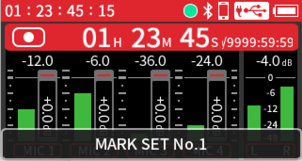
Set this by pressing the MENU button and using MARK/SLATE TONE > MARK > SKIP MODE.
When the Home Screen is open and the transport indicator is lit, the and buttons can be pressed to move to earlier and later subject marks. When there are no subject marks, they will skip to the previous or next file.
Skipping is disabled when the mark skipping function is OFF.
Options: OFF (default), ALL, MANUAL, TIME, PEAK, BUFFER OVERFLOW
Use the BROWSE Screen file menu to delete marks. (Deleting marks)
See “Viewing mark lists” for details.
11-1.Setting output for camera use
Set this by pressing the MENU button and using OUTPUT > OUTPUT.
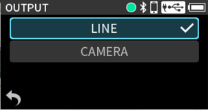
LINE (default)
Output from the /TC/LINE OUT jack will not be attenuated.
By adjusting the OUTPUT LEVEL, it can be attenuated 0 to −60 dB.
CAMERA
Output from the /TC/LINE OUT jack will be attenuated by −20 dB.
By adjusting the OUTPUT LEVEL, it can be attenuated by −20 – −80 dB. This enables inputting audio to the camera at a suitable level.
See “5-4. Output settings” for details about adjusting the OUTPUT LEVEL.
Set the Fn button function to MARK/SLATE. Then, conduct the operations below. (Assigning the Fn button function)
When recording or monitoring, press and hold the Fn (MARK/SLATE) button to output a slate stone.
When recording, slate tones will be added to files.
NOTE
In order to prevent misoperation, the button must be held briefly to add a slate tone.
Slate tones are output from the /TC/LINE OUT jack.
Marks are added at positions where slate tones are added manually.
11-3.Using the auto tone function
The auto tone function can be used to automatically insert a slate tone whenever recording starts and stops.
By connecting the /TC/LINE OUT jack to the audio input jack of a camera, both units can record the same slate tones to their files. These tones can be used as guides to synchronize files in video editing software.
Press the MENU button and open MARK/SLATE TONE.
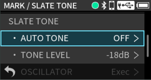
Set this using AUTO TONE.
The location where slate tones are added can be set.
OFF (default)
Slate tones will not be added.
HEAD
Tone signals are only inserted at the start of recording.
HEAD+TAIL
Tone signals are inserted at both the start and end of recording.
Set this using TONE LEVEL.
This sets the tone volume.
Options: −12dB, −18dB (default), −24dB, −30dB, −36dB
Set this using OSCILLATOR.
A tone will be output at the selected level.
Use this to check the level on a connected camera.
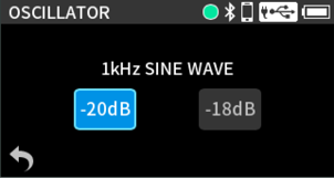
12-1.Exchanging files with computers
Refer to “4-5. Computers and smartphones” and connect with a computer beforehand.
Setting this unit for use as a card reader
Press the MENU button and open SD CARD > SD CARD READER.
|
|
|
|
|
|
The unit display will change. The SD card in the unit can be accessed when it is recognized by the computer.
Open the “FR-AV4” drive on the computer to show the “SOUND” and “UTILITY” folders.
To transfer files from the computer, copy the desired audio files on the computer to the SOUND folder. To transfer files from the SD card to the computer, copy the desired audio files from the SOUND folder to any folder on the computer.
TIP
Subfolders can be created in the SOUND folder. This unit cannot recognize subfolders and files beyond three levels.
Follow the specified procedures for the computer to remove the media. Then, tap the icon at the bottom left of the screen.

NOTE
Follow the procedures specified for the computer to disconnect the media from it before removing the SD card from the unit or ending SD CARD READER operation.
12-2.Connecting with iOS devices
To connect with an iOS device with a lightning connector, a Lightning to USB Camera Adapter and a USB cable (Type-A to Type-C) are necessary.
To connect with an iOS device with a Type-C connector, a USB cable (Type-C to Type-C) is necessary.
Install batteries and turn off the USB BUS POWER item.
NOTE
This unit will not provide power to an iOS device when they are connected.
With Windows, an ASIO driver for the FR-AV4 can be used. Check the page for this product on the TASCAM website for details.
https://tascam.jp/int/product/fr-av4/support
NOTE
With a Mac, the standard OS driver will be used, so there is no need to install any software.
12-4.Using as an audio interface
This unit can be used as a USB audio interface by connecting it with a computer using a USB cable.
NOTE
This unit cannot be used as a USB audio interface if its sampling frequency is 192 kHz.
Sound played back on this unit can be output over USB.
When an SD card is loaded
Manually set this unit and the computer to use the same sampling frequencies.
See “7-2. Changing the recording file format” for procedures to change the sampling frequency of this unit.
After changing the sampling frequency, starting recording will cause audio to be transmitted.
When an SD card is not loaded
This unit will operate using the sampling frequency of the computer.
FR-AV4 USB audio channel assignments
|
USB channels |
Signals |
|
USB IN 1-2 |
Stereo mix |
|
USB IN 3-4 |
Inputs 1–2 |
|
USB IN 5-6 |
Inputs 3–4 or input signals from |
Only the INPUT LEVEL and PHASE settings are enabled for the selected inputs and applied to the signals sent to the computer.
NOTE
The automatic power saving function is disabled when being used as a USB audio interface. (16-6. Using the automatic power saving function)
Inputting sound to the computer using the unit inputs
1.Use a USB cable to connect the computer and the unit.
2.Set the audio input device to “FR-AV4” on the computer.
Set this unit and the computer to use the same bit depths and sampling frequencies.
3.Turn on “CH ENABLE” for the channels to be used as inputs to the computer.
|
|
|
|
|
|
4.Turn off “CH ENABLE” for the channels not to be used as inputs to the computer.
Mixing the computer output into the unit master track
Press the MENU button and use PREFERENCES > USB RETURN to set this.
CH INPUT (default)
Use the computer output sound as channel input sound.
MASTER
Mix the computer output sound into the master track of the mixer.
Using the computer output as sound input to this unit
Select CH INPUT for the USB RETURN item beforehand.
1.Use a USB cable to connect the computer and the unit.
2.Set the audio output device to “FR-AV4” on the computer.
Set this unit and the computer to use the same bit depths and sampling frequencies.
3.Select USB as the input source of channels to assign sound from the computer to them.
|
|
|
|
|
|
|
|
|
|
4.Turn on CH ENABLE for channels with USB assigned.
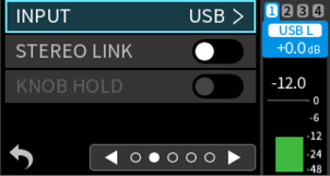
NOTE
Adjust the USB volume on the output device.
This unit can be controlled from an iOS/Android device using the TASCAM RECORDER CONNECT controller app if an AK-BT2 Bluetooth adapter (sold separately) is connected to its Bluetooth adapter connector.
TASCAM RECORDER CONNECT can simultaneously control up five supported devices (including FR-AV4, FR-AV2 and DR-10L Pro models).
Check the page for this product on the TASCAM website for details, including about how to use the app.
https://tascam.jp/int/product/fr-av4/support
|
CAUTION
|
NOTE
The unobstructed transmission distance of the AK-BT2 Bluetooth adapter is about 10 m. (The transmission distance is only an estimate. The transmission distance may vary depending on the surrounding environment and radio wave conditions.)
13-1.Installing the dedicated controller app
1.Connect the device on which the app will be installed to the Internet.
2.Search for “TASCAM RECORDER CONNECT” on Google Play for an Android device or on the App Store for an iOS device. Then, download and install it.
Please be aware that you are responsible for any transmission costs related to Internet connection.
iOS
|
|
https://apps.apple.com/us/app/tascam-recorder-connect/id1667424244 |
Android
|
|
https://play.google.com/store/apps/details?id=com.tascam.jp.android.DR10LProCONNECT&hl=en&gl=us |
13-2.Installing a Bluetooth® adapter
1.Remove the cover from the Bluetooth connection device port on this unit, replace the dummy plug and insert an AK-BT2 (sold separately) in the port.
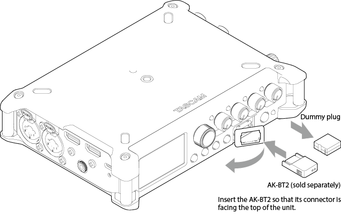
2.Reattach the cover in its original place.
NOTE
If no Bluetooth adapter has been installed, the BLUETOOTH menu items and the TIMECODE menu ATOMOS item will appear gray and cannot be used.
13-3.Connecting with the dedicated control app
|
CAUTION
Always launch TASCAM RECORDER CONNECT and conduct pairing.
|
1.Enable Bluetooth connection on the smartphone or tablet.
NOTE
Refer to the operation manual of the Bluetooth device for procedures.
2.Launch TASCAM RECORDER CONNECT.
|
|
|
|
|
Bluetooth device screen |
3.Press the MENU button on the unit and turn BLUETOOTH > REMOTE CONTROL on (![]() ).
).
The default is off.
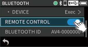
4.Operate the TASCAM RECORDER CONNECT app to connect to the unit.
The connection status can be checked with the blinking state of the smartphone icon at the top right of the Home Screen.
|
Blinking state |
Status |
|
Unlit |
Remote control function off |
|
Blinking |
Waiting to pair |
|
Lit |
Paired |
When connection completes, the display of the smartphone or tablet will automatically switch to the operation screen.
NOTE
See the TASCAM RECORDER CONNECT operation manual for details about using the control app.
In the control app, this unit will be recognized according to its MENU > BLUETOOTH > BLUETOOTH ID setting.
13-4.Wireless timecode synchronization with supported Atomos products
By connecting an AK-BT2 Bluetooth adapter (sold separately) to this unit, connection is possible to receive timecode from, for example, AtomX SYNC and UltraSync BLUE devices by Atomos Pty Ltd.
Received timecode is written to the files recorded by this unit. Using this timecode data simplifies the aligning of video and audio files created by multiple units.
Connecting with supported Atomos products
1.Press the MENU button on the unit and turn TIMECODE > ATOMOS on (![]() ).
).
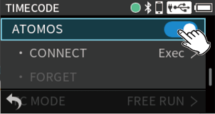
2.Tap ATOMOS  CONNECT.

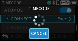
After pairing completes, “CONNECT” will appear dimmed.
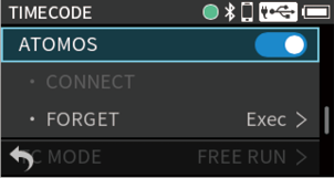
Pairing operations are also necessary on the Atomos product being paired. For procedures, refer to the operation manual of the product being used.
Press the MENU button and set SETTINGS > TIMECODE > MASTER to “ATOMOS”. (14-2. MASTER)
See “14-7. Timecode information” for details about checking timecode information.
Disconnecting from supported Atomos products
Press the MENU button on the unit and turn TIMECODE > ATOMOS off (![]() ).
).
Connecting a different AtomX SYNC, UltraSync BLUE or similar device
Unpairing first is necessary to switch connection from an already paired AtomX SYNC/UltraSync BLUE or similar device to a different device.
1.Press the MENU button on the unit and turn TIMECODE > ATOMOS on (![]() ).
).
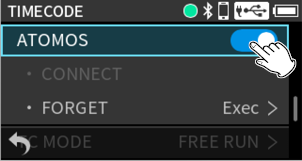
2.Tap TIMECODE > ATOMOS FORGET to clear pairings.
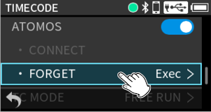
3.Follow the procedures in "Connecting with supported Atomos products” again to connect a different AtomX SYNC, UltraSync BLUE or similar device
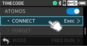
TIMECODE operation status
|
Blinking green* |
|
Receiving timecode and operating with synchronization |
|
Blinking red* |
|
Running by itself based on the last received timecode |
|
Unlit |
|
Not operating with timecode |
* Blinks when connected to AtomX SYNC/UltraSync BLUE
Using remote control while timecode is running free
The remote control app can be used with the unit running free using the timecode that it last received.
1.Synchronize timecode with the supported Atomos product. (Connecting with supported Atomos products)
2.End timecode synchronization with the supported Atomos product. (Disconnecting from supported Atomos products)
The unit will start running freely based on the last received timecode data.
NOTE
Free running will use the clock position of this unit.
3.Connect with the TASCAM RECORDER CONNECT dedicated control app. (13-3. Connecting with the dedicated control app)
The above procedures allow the remote control app to be used with the unit while it is running free using the timecode that it last received.
Press the MENU button and use TIMECODE to open the TIMECODE Settings Menu.
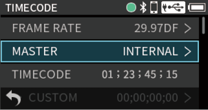
The FRAME RATE can be changed when MASTER is not set to "ATOMOS” or “HDMI”.
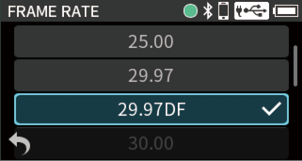
Options: 23.98, 24.00, 25.00, 29.97, 29.97DF (default), 30.00, 30.00DF, 50.00, 60.00
NOTE
When MASTER is “TC IN”, FRAME RATE will be set automatically to match the timecode input through the TC IN jack.
When MASTER is “ATOMOS” or “HDMI”, the FRAME RATE being used for operation will be shown.
When set to 50.00 or 60.00, the actual timecode generated will use 25.00 or 30.00 as the frame rate.
Picture can be set to 50.00 or 60.00 frames, but LTC Timecode cannot be set higher than 30.00 frames due to the standard.
For this reason, half the frame rate is normally used to synchronize with timecode when recording video at 50.00 or 60.00 frames.
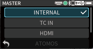
INTERNAL (default)
This sets the FR-AV4 as the timecode master.
Timecode is generated from the time of the unit's built-in clock.
TC IN
This sets the timecode input from the TC IN jack as the master. The unit jam syncs according to the input timecode.
HDMI
This sets the timecode input from the HDMI® IN jack as the master.
ATOMOS
This sets Bluetooth timecode from an ATOMOS device as the master.
Receiving timecode through the TC IN jack
Set MASTER to “TC IN”.
|
|
|
|
|
|
To receive timecode from the TC IN jack, input must be in the specified level range for LTC (0.5–5.0 Vpp).
After receiving timecode, if the cable connected to the TC IN jack is disconnected, the unit will run freely based on the last timecode data that it received (jam sync).
Receiving timecode by Bluetooth®
Set MASTER to “ATOMOS” and turn TIMECODE > ATOMOS on. See “13-4. Wireless timecode synchronization with supported Atomos products” for details.
Set MASTER to “HDMI”.
See “Timecode connection examples” for details about device connection.
TIMECODE shows the current timecode (hours: minutes: seconds: frames).
Timecode can be restarted by using the RESTART function.
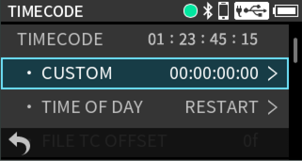
CUSTOM
The timecode can be set to any value.
On the TIMECODE CUSTOM Screen, tap "SET" to restart from the set timecode.
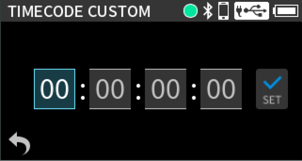
See “Inputting numbers” for details about number input.
The timecode will restart from the time of the built-in clock.
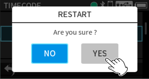
NOTE
If MASTER is set to “ATOMOS” or “HDMI”, this will appear gray and RESTART will not be usable.
If MASTER is set to “TC IN” and timecode is being input, restarting will not occur.
FILE TC OFFSET
The value set for timecode can be offset.
By using this function, timecode values can be aligned if differences occur between the timecodes recorded on the camera and this unit.
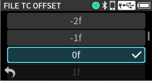
|
CAUTION This function can only be applied when MENU > TIMECODE > MASTER is set to "HDMI". |
NOTE
Differences between audio recorded with video by a camera and audio recorded by this unit might change depending on the camera resolution setting.
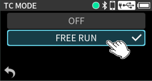
OFF
Timecode will not be used.
Timecode will not be shown on the Home Screen.
FREE RUN (default)
Timecode will be used.
Timecode will be shown on the Home Screen.
When TC MODE is “FREE RUN”, the display positions of the counter and timecode on the Home Screen can be switched.
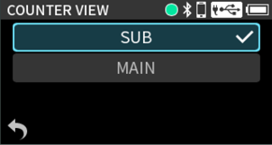
SUB (default)
Timecode will be shown in the timecode area at the top left of the Home Screen.
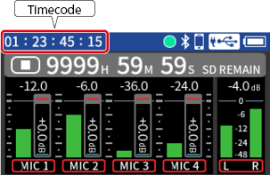
MAIN
Timecode will be shown in the project status bar.
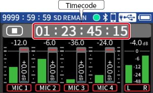
Timecode can be output from the TC OUT jack by setting TC MODE to “FREE RUN”.
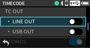
LINE OUT
Timecode will be output from the /TC/LINE OUT jack. The R channel outputs LINE OUT audio. Select this to input the timecode output to a camera. (50 mVpp)
Options: Off (default), On
USB OUT
Timecode will be output on one channel of the signal sent to USB. Select this to input timecode to a smartphone, tablet or similar device.
Options: Off (default), On
When outputting audio from the LINE OUT, turn off the LINE OUT item.
This shows the timecode that is being received or sent.
|
|
|
|
|
|
TIMECODE
This shows the timecode as hours: minutes: seconds: frames.
USERBITS
This shows the user bits (date, time, scene number or other chosen data) set on the AtomX SYNC, UltraSync BLUE or another device.
FRAME RATE
This shows the frame rate.
DEVICE
This shows the name of the AtomX SYNC/UltraSync BLUE or other device.
15. Wireless audio monitoring functions
15-1.Wireless audio monitoring
By connecting an AK-BT2 Bluetooth adapter (sold separately), monitoring sound from this unit can be output to devices that support Bluetooth, including earphones and speakers. (13-2. Installing a Bluetooth® adapter)
Press the MENU button and turn on BLUETOOTH > AUDIO MONITORING (![]() ).
).
The default value is off.
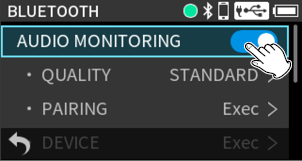
Enable Bluetooth transmission on the earphone, speaker or other device that supports Bluetooth. Then, conduct the following operations.
Pairing this unit with an earphone, speaker or other device that supports Bluetooth is necessary to connect this unit for the first time or to connect with a different Bluetooth-compatible device for the first time.
|
CAUTION This display of this unit can only show half-width (normal) alphabet letters and numbers (single-byte). If a device name uses Japanese, Chinese or other full-width characters (double-byte characters), pairing is possible, but the name cannot be shown correctly. |
1.Tap “PAIRING”.
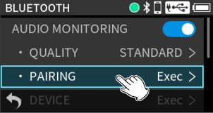
2.Tap the name of the device to connect in the list.
|
|
|
|
|
|
|
|
|
|
After connection, the normal monitoring sound will be output.
NOTE
This unit can save data for pairings with up to 20 Bluetooth devices.
To add a new pairing when 20 devices have already been saved, delete the data for an unnecessary pairing. (15-5. Deleting pairing data)
Use the headphone VOLUME knob to adjust the volume of wireless audio monitoring.
See “Selecting the headphone volume knob function” for details.

15-4.Connecting with already paired devices
Press the MENU and set BLUETOOTH > AUDIO MONITORING.
1.Tap AUDIO MONITORING DEVICE.

2.Tap the device to connect.

3.Tap “CONNECT”.
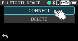
4.Tap “YES”.
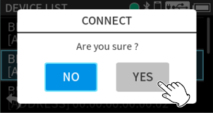
A check will appear next to the device name after connection completes.
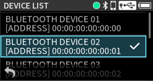
This unit can save pairings with up to 20 Bluetooth devices.
Delete this data to prevent automatic connection.
1.Tap AUDIO MONITORING DEVICE.
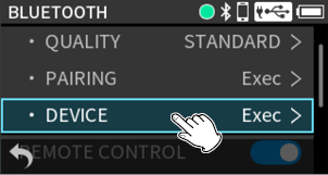
2.Tap the device to delete.
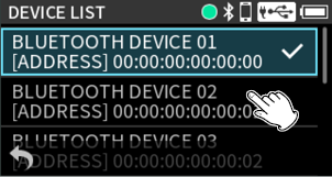
3.Tap “DELETE”.
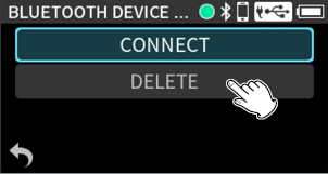
4.Tap “YES”.
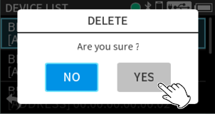
1.Tap AUDIO MONITORING QUALITY.
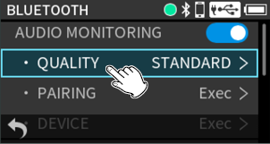
2.Tap a quality to change it.
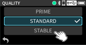
3.Tap “YES”.
|
|
|
|
|
|
PRIME
This setting prioritizes quality. Connection stability could worsen depending on radio wave conditions.
STANDARD (default)
This setting balances audio quality and connection stability.
STABLE
This setting prioritizes connection stability. The audio quality will be worse compared to other settings because the transmission rate is lowered.
NOTE
The sound of wireless audio monitoring will be slightly delayed compared to the sound being recorded or played by the unit. The delay time could vary depending on the surrounding environment and radio wave conditions.
The delay time is also affected by the QUALITY setting. The order from most to least is PRIME, STANDARD, STABLE.
If the QUALITY setting is changed while connected to headphones, speakers or other devices that support Bluetooth, they will automatically reconnect after disconnecting once.
16-1.Using a 2D code to access the Owner’s Manual web page
The URL for a website that has the Owner’s Manual can be shown as a 2D code on the display of this unit.
By using a device to scan the 2D code, a document page on the website can be accessed.
NOTE
Please be aware that you are responsible for any transmission costs related to Internet connection.
1.Press the MENU button and use INFORMATION > MANUALS to view The DOCUMENT PAGE Screen.
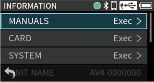
2.Use a smartphone or similar device to scan the 2D code on the display to access a page with the Owner’s Manual for this unit.
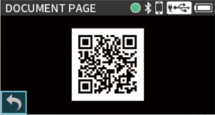
16-2.Showing various information
Press the MENU button and use INFORMATION.
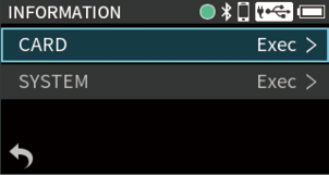
Card information
Press the MENU button and use INFORMATION > CARD to view SD card information.
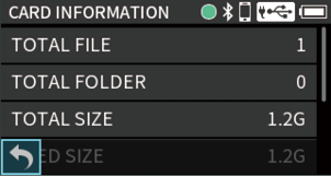
Press the MENU button and use INFORMATION > SYSTEM to view firmware and hardware versions.
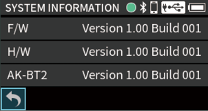
This shows the unit name set using the TASCAM RECORDER CONNECT app.
This shows the name of the source device connected to the HDMI IN port. Depending on the device, acquiring the name might not be possible.
This shows the name of the sync device connected to the HDMI OUT port. Depending on the device, acquiring the name might not be possible.
16-3.Resetting the date and time
Do this by pressing the MENU button and selecting DATE/TIME. See “3-5. Set the date and time” for operation procedures.
16-4.Resetting the unit to its factory defaults
Do this by pressing the MENU button and selecting FACTORY PRESET.
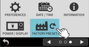
NOTE
This will also delete data added for AUDIO MONITORING. Conduct pairing again.
The date and time setting is not erased.
Do this by pressing the MENU button and selecting SD CARD > FORMAT SD. See “3-6. Formatting (initializing) SD cards” for operation procedures.
16-6.Using the automatic power saving function
Set this using MENU > POWER/DISPLAY > AUTO POWER SAVE.
When on, the unit automatically turns off after 30 minutes have elapsed since the last activity or operation.
Options: Off (default), On
NOTE
This function only works when the unit is stopped. This function will not cause the unit to turn off during recording or playback.
To record using ambisonic mics, set the ambisonic mode.
Press the MENU button and set MS DECODE/AMBISONICS > AMBISONICS.
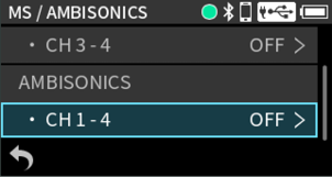
CH 1–4
This sets the ambisonic recording format.
Options: OFF (default), A FORMAT, B FORMAT (FuMa), B FORMAT (AmbiX)
When AMBISONICS is enabled, use HOME > INPUT > MIC to set the mic orientation.
MIC
This sets the orientation of the ambisonic mic.
UPRIGHT
Record with the mic oriented up
UPSIDEDOWN
Record with the mic oriented down
ENDFIRE
Record with the mic oriented forward
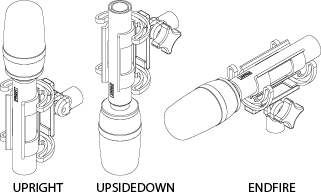
If the ambisonic recording mode is set to anything other than "OFF" settings will change as follows.
Input settings will be shared by channels 1–4.
Mixer functions will be disabled.
Compensation for mic distances (DELAY) will be disabled.
Input phase inversion (PHASE INVERT) will be disabled.
Channels 1–4 will be assigned to group 1 in the input GANG settings. All inputs will operate at the same level.
The plugin power function will be disabled.
The following table shows the correspondence between input channels and audio signals when ambisonic mode is on.
|
Setting |
1 |
2 |
3 |
4 |
|
A format |
FLU |
FRD |
BLD |
BRU |
|
B format (FuMa) |
W |
X |
Y |
Z |
|
B format (AmbiX) |
W |
Y |
Z |
X |
16-8.Selecting the power source
Set this using MENU > POWER/DISPLAY > USB BUS POWER.
OFF
The unit will operate using battery power. No power will be supplied from USB.
ON (default)
The unit will operate using battery power, but USB power supply will be prioritized if power is connected to the USB port.
|
CAUTION When selecting BATTERY as the power source, always put batteries in this unit. |
NOTE
When connecting this unit with an iOS device, set this to OFF.
16-9.Setting the AA battery type
Set this using MENU > POWER/DISPLAY > BATTERY.
Use this to set the type of battery used.
This setting is used to show the amount of remaining battery charge and determine if the unit has enough power for normal operation.
If this is not set correctly, the power might turn off even if there is enough remaining battery charge.
ALKALI (default)
Alkaline batteries (default)
Ni-MH
Nickel-metal hydride batteries
LITHIUM
Lithium batteries
16-10.Saving and recalling user settings
Do this by pressing the MENU button and using USER PRESET.
Unit settings can be saved (SAVE) and recalled (LOAD).
A maximum of 5 presets can be saved.
NOTE
Before saving and when the FACTORY PRESET is loaded, they will be set to their default values.
The following settings are not saved.
- USB BUS POWER (OFF / ON)
- BATTERY (ALKALI / Ni-MH / LITHIUM)
- FILE NUMBER
16-11.Power saving (energy conservation) mode
Set this using MENU > POWER/DISPLAY > POWER SAVE MODE.
POWER SAVE MODE
When the power saving mode is on, the following functions are limited to reduce power consumption.
Only 48 kHz can be selected as the sampling frequency.
Phantom power is turned off. Condenser mics with balanced connections to XLR jacks cannot be used.
The backlight illumination time of the display is fixed at 30 seconds.
The display brightness setting is fixed to MID.
The peak indicators do not light.
The display contrast setting is fixed to 10.
BACKLIGHT
This sets the display backlight.
OFF: Backlight always off
5–30 sec: Backlight turns off automatically after set time without operation
ALWAYS: Backlight always stays on (default)
NOTE
The backlight setting is only active during battery operation. The backlight will always stay lit when operating on USB bus power.
BRIGHTNESS
This sets the display backlight brightness.
INDICATORS
This sets how the REC and peak indicators light.
ALL ON: The REC and peak indicators light. (default)
PEAK LED OFF: The peak indicators do not light.
REC LED OFF: The REC indicators do not light.
ALL OFF: The REC and peak indicators do not light.
INDICATORS DIMMER
This lowers the brightness of the REC and peak indicators.
Off (default): Indicators light at regular brightness
On: Indicators light at reduced brightness
NOTE
When the POWER SAVE MODE is on, backlight, brightness and indicator settings cannot be made.
If the POWER SAVE MODE is on when operating using battery power, the backlight will dim after 30 seconds without use.
Pressing a button will cause the backlight to light, making operation possible.
16-12.Adjusting the display contrast
Set this using MENU > POWER/DISPLAY > CONTRAST.
The display contrast can be set between 0 and 20.
The default value is 10.
The amount of time that peak indicators 1–4 stay lit as well as the peak hold display for the level meters can be changed.
Press the MENU button and use PREFERENCES > PEAK HOLD to set this.
Options: OFF (no peak hold), 1 sec (default), 2 sec,10 sec, HOLD (stay held)
NOTE
When the Home Screen is open, turning the DATA dial will reset peak hold display.
Structure of the Menu Screen
The menus shown depend on the use and operation conditions of the unit.
|
Menu Screen (when stopped) - page 1 |
||||
|
MIXER |
||||
|
PHANTOM |
CH1/CH2/CH3/CH4, +24V/+48V (default) |
|||
|
PHONES VOLUME |
||||
|
BLUETOOTH |
||||
|
BROWSE |
||||
|
SD CARD |
||||
|
TIMECODE |
||||
|
HDMI AUDIO ASSIGN |
||||
|
Menu Screen (when stopped) - page 2 |
||||
|
REC SETTINGS |
||||
|
INPUT KNOB SETTINGS |
||||
|
MS DECODE/AMBISONICS |
||||
|
OUTPUT |
||||
|
MARK/SLATE TONE |
||||
|
AUTO MIXER |
||||
|
Menu Screen (when stopped) - page 3 |
||||
|
PREFERENCES |
||||
|
DATE/TIME |
||||
|
INFORMATION |
||||
|
POWER/DISPLAY |
||||
|
FACTORY PRESET |
||||
|
USER PRESET |
||||
|
Menu Screen (when recording) |
||||
|
MIXER |
||||
|
OUTPUT |
||||
|
PHONES VOLUME |
||||
|
BLUETOOTH |
||||
|
INPUT KNOB SETTINGS |
||||
|
AUTO MIXER |
||||
|
Menu Screen (when transport active) |
||||
|
HOME |
||||
|
OUTPUT |
||||
|
PHONES VOLUME |
||||
|
BLUETOOTH |
||||
|
BROWSE |
||||
|
MONITOR |
||||
|
MIXER |
||||
|
AUTO MIXER |
||||
|
PAN |
L20 – L1, C (default), R1 – R20 |
|||
|
FADER |
10 dB – 0 dB (default) – −inf |
|||
|
MASTER FADER |
10 dB – 0 dB (default) – −inf |
|||
|
MASTER REC ENABLE |
Off / On (default) |
|||
|
OUTPUT LEVEL |
−60, −59 – 0 dB (default) |
|||
|
OUTPUT |
LINE (default), CAMERA |
|||
|
LIMITER |
Off (default) / On |
|||
|
DELAY |
0 (default) – 300ms |
|||
|
AUDIO MONITORING |
Off (default) / On |
|||||
|
QUALITY |
PRIME, STANDARD (default), STABLE |
|||||
|
PAIRING |
Exec |
|||||
|
DEVICE |
Exec |
|||||
|
REMOTE CONTROL |
Off (default) / On |
|||||
|
BLUETOOTH ID |
||||||
|
FILE |
||||||
|
SELECT |
||||||
|
FILE DELETE |
||||||
|
RENAME |
Exec |
|||||
|
CHANGE PROTECT |
||||||
|
FILE INFORMATION |
||||||
|
MARK |
Exec |
|||||
|
FOLDER |
||||||
|
OPEN |
||||||
|
RENAME |
Exec |
|||||
|
ALL FILES DELETE |
||||||
|
FOLDER DELETE |
||||||
|
SD CARD READER |
Exec |
|||||||
|
FORMAT SD |
QUICK FORMAT, ERASE FORMAT |
|||||||
|
FRAME RATE |
23.98, 24.00, 25.00, 29.97, 29.97DF (default), 30.00, 30.00DF, 50.00, 60.00 |
|||||
|
MASTER |
INTERNAL (default), TC IN, HDMI, ATOMOS |
|||||
|
TIMECODE |
||||||
|
CUSTOM |
Exec |
|||||
|
TIME OF DAY |
Exec |
|||||
|
FILE TC OFFSET |
−10 f – 0 f (default) – +10 f |
|||||
|
INFORMATION |
Exec |
|||||
|
COUNTER VIEW |
SUB (default), MAIN |
|||||
|
TC OUT |
||||||
|
LINE OUT |
Off (default) / On |
|||||
|
USB OUT |
Off (default) / On |
|||||
|
ATOMOS |
Off (default) / On |
|||||
|
CONNECT |
Exec |
|||||
|
FORGET |
Exec |
(Connecting a different AtomX SYNC, UltraSync BLUE or similar device) |
||||
|
TC MODE |
OFF, FREE RUN (default) |
|||||
|
HDMI OUT 1–2 |
CH 1–2, CH 3–4, MASTER, THRU (default) |
|||
|
HDMI OUT 3–4 |
CH 1–2, CH 3–4, MASTER, THRU (default) |
|||
|
HDMI OUT 5–6 |
CH 1–2, CH 3–4, MASTER, THRU (default) |
|||
|
HDMI OUT 7–8 |
CH 1–2, CH 3–4, MASTER, THRU (default) |
|||
|
SAMPLING RATE |
48kHz (default), 96kHz, 192kHz |
|||||||
|
BIT DEPTH |
24bit, 32-bit float (default) |
|||||||
|
POLY |
Off (default) / On |
|||||||
|
MASTER REC ENABLE |
Off / On (default) |
|||||||
|
DUAL FORMAT |
Off (default) / On |
(Simultaneous recording of mix files in WAV and MP3 formats (dual format function)) |
||||||
|
PRE REC |
Off (default) / On |
|||||||
|
FILE NAME |
TEXT, DATE (default), UNIT NAME |
|||||||
|
TEXT |
AV4-00000 (default) |
|||||||
|
NUMBER |
Exec |
|||||||
|
GANG |
Exec |
|||||||
|
MIN MUTE |
Off (default) / On |
|||||||
|
HOLD |
Off (default) / On |
|||||||
|
MS DECODE |
||||||||
|
CH 1–2 |
OFF (default), REC, MONITOR |
|||||||
|
CH 3–4 |
OFF (default), REC, MONITOR |
|||||||
|
AMBISONICS |
||||||||
|
CH 1–4 |
OFF (default), A FORMAT, B FORMAT (FuMa), B FORMAT (AmbiX) |
|||||||
|
MARK |
||||||||
|
SKIP MODE |
OFF (default), ALL, MANUAL, TIME, PEAK, BUFFER OVERFLOW (BOF) |
|||||||
|
TIME MARK |
OFF (default), 5min, 10min, 15min, 30min, 60min |
|||||||
|
PEAK MARK |
Off (default) / On |
|||||||
|
SLATE TONE |
||||||||
|
AUTO TONE |
OFF (default), HEAD, HEAD+TAIL |
|||||||
|
TONE LEVEL |
-12dB, -18dB (default), -24dB, -30dB, -36dB |
|||||||
|
OSCILLATOR |
Exec |
|||||||
|
AUTO POWER SAVE |
Off (default) / On |
|||||||
|
Off / On (default) |
||||||||
|
BATTERY |
ALKALI (default), Ni-MH, LITHIUM |
|||||||
|
POWER SAVE MODE |
Off (default) / On |
|||||||
|
BACKLIGHT |
OFF, 5sec, 10sec, 15sec, 30sec, ALWAYS (default) |
|||||||
|
BRIGHTNESS |
LOW, MID (default), HIGH |
|||||||
|
INDICATORS |
ALL ON (default), PEAK LED OFF, REC LED OFF, ALL OFF |
|||||||
|
INDICATORS DIMMER |
Off (default) / On |
|||||||
|
CONTRAST |
0 – 10 (default) – 20 |
|||||||
|
Fn KEY |
MARK, SLATE, SLATE, MIXER, PHANTOM, PHONES VOLUME, BLUETOOTH, BROWSE, SD CARD, TIMECODE, HDMI, AUTO MIXER |
|||||||
|
PEAK HOLD |
OFF, 1 sec (default), 2 sec, 10 sec, HOLD |
|||||||
|
USB RETURN |
CH INPUT (default), MASTER |
|||||||
|
MANUALS |
Exec |
(16-1. Using a 2D code to access the Owner’s Manual web page) |
||||||
|
CARD |
Exec |
|||||||
|
SYSTEM |
Exec |
|||||||
|
UNIT NAME |
FR-AV4 (default) |
|||||||
|
HDMI IN |
||||||||
|
HDMI OUT |
||||||||
|
SAVE |
USER PRESET 1–5 |
|||||||
|
LOAD |
USER PRESET 1–5 |
|||||||
|
INPUT |
||||
|
CH ENABLE |
Off (default) / On |
|||
|
REC ENABLE |
Off (default) / On |
|||
|
PHANTOM |
Off (default) / On |
|||
|
INPUT |
MIC (default), LINE, EXT (CH 3-4 only), USB |
|||
|
STEREO LINK |
Off (default) / On |
|||
|
KNOB HOLD |
Off (default) / On |
|||
|
PLUG IN POWER |
OFF (default), 2.5V, 5V |
|||
|
MIC |
UPRIGHT (default), UPSIDEDOWN, ENDFIRE |
|||
|
DELAY |
0 (default) – 300ms |
|||
|
LOW CUT |
OFF (default), 40Hz, 80Hz, 120Hz, 220Hz |
|||
|
LIMITER |
Off (default) / On |
|||
|
EQ |
OFF (default), ON (Exec) |
|||
|
NOISE GATE |
OFF (default), LOW, MID, HIGH |
|||
|
PHASE INVERT |
Off (default) / On |
|||
|
PRESET SAVE |
PRESET 1, PRESET 2, PRESET 3, PRESET 4, PRESET 5 |
|||
|
PRESET LOAD |
PRESET 1, PRESET 2, PRESET 3, PRESET 4, PRESET 5 |
|||
|
EQ |
||||
|
LOW GAIN |
−12 dB – 0 dB (default) – +12 dB (1dB steps) |
|||
|
LOW FREQ |
32 Hz–1.6 kHz (default: 150 Hz) |
|||
|
L-MID GAIN |
−12 dB – 0 dB (default) – +12 dB (1dB steps) |
|||
|
L-MID FREQ |
32 Hz–18.0 kHz (default: 300 Hz) |
|||
|
L-MID Q |
0.25, 0.5, 1.00 (default), 2.00, 4.00, 8.00, 16.00 |
|||
|
H-MID GAIN |
−12 dB – 0 dB (default) – +12 dB (1dB steps) |
|||
|
H-MID FREQ |
32 Hz–18.0 kHz (default: 4.0 kHz) |
|||
|
H-MID Q |
0.25, 0.5, 1.00 (default), 2.00, 4.00, 8.00, 16.00 |
|||
|
HIGH GAIN |
−12 dB – 0 dB (default) – +12 dB (1dB steps) |
|||
|
HIGH FREQ |
1.7 kHz–18.0 kHz (default: 8.0 kHz) |
|||
The AUTO MIXER function was added in FR-AV4 version 1.10.
The AUTO MIXER is a function for reducing mixing work when recording talks and meetings. The AUTO MIXER in the FR-AV4 uses a gain sharing technique to realize natural-sounding mixes of situations with multiple speakers while suppressing noise.
Features
Gain sharing technique
While maintaining a fixed total gain for multiple channels, gain shares are automatically allocated with priority given to channels that have people speaking.
Noise reduction
The noise level of the mix is reduced by lowering the gain of channels that do not have speaking.
Excessive input prevention
Excessive input to the mix is prevented by maintaining a fixed total gain level.
Simple parameters
Separate on/off for every channel
Weight (gain allocation adjustment when silent)
NOTE
The AUTO MIXER only effects channels when it is turned on for them.
This function is not suitable for use with music.
The AUTO MIXER function is enabled only when the sampling frequency is 48 kHz.
If MS DECODE or AMBISONICS is enabled, the AUTO MIXER function will be disabled.
Using the AUTO MIXER function
1.Adjust input levels so that they are about the same for the voice of each speaker.
Set all the Mixer Screen faders to 0 dB.
2.Press the MENU button.
The Menu Screen will open.
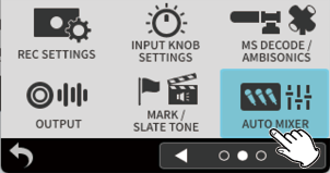
3.Select AUTO MIXER.
This opens the AUTO MIXER Screen.
4.Tap channels to turn on the AUTO MIXER function for them.
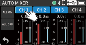
The ALL ON and ALL OFF buttons can be used to turn all channels on/off at once.
5.Adjust the WEIGHT slider for each channel.
When no one is speaking, adjust the WEIGHT sliders so that the gain level meters of all channels are equal.
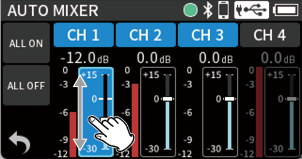
NOTE
The gain level meter values show the allocation of gain to each channel.
The WEIGHT parameter is for balancing noise levels when silent.
This can be adjusted between +15 dB and −30 dB (0 dB by default) in 0.5dB increments.
On the HOME/MIXER Screen, AUTO MIXER status can be checked with the [A] icons.
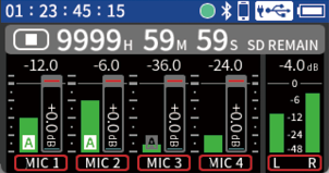
|
AUTO MIXER setting |
Gain level meter |
[A] icon |
|
On |
−12 dB or higher |
|
|
On |
Less than −12 dB |
|
|
Off |
0 dB |
No indicator |
Fader operation on the Mixer Screen
If a speaker’s voice is too loud or too quiet, adjust the fader slightly on the Mixer Screen.
The following is a list of the pop-up messages.
Refer to this list if one of these pop-up messages appears on the FR-AV4 and you want to check the meaning or determine a proper response.
|
Message |
Details and response |
|---|---|
|
No Card |
Load an SD card. |
|
Card Error |
The SD card was not recognized. Replace the SD card. |
|
Card Full |
The SD card has no remaining capacity. |
|
Format Error |
The SD card is not formatted properly or the card is broken. Select “OK” to start formatting. Formatting will erase all the data on the SD card. |
|
Invalid Card |
Something might be wrong with the SD card. Replace the SD card. |
|
MBR ERROR |
The SD card is not formatted properly or the card is broken. Tap the screen to start formatting. Formatting will erase all the data on the SD card. If formatting is not possible, change the SD card. |
|
Write error |
Writing to the SD card timed out. This has caused audio to be interrupted and noise to occur. A BOF mark was added at the point when audio was interrupted. |
|
Card slow |
SD card writing performance has become worse. A BOF mark has been added at the point when audio was interrupted because writing to the SD card timed out. Check the audio around the BOF mark. Execute the erase format function or change the SD card. |
|
Invalid SysFile |
The system file required to operate this unit is invalid. Replace the SD card or tap the screen to create a system file. |
|
Non- Supported |
The file cannot be played by this unit. Please see “Recording/playback formats” for file formats that this unit can use. |
|
File Num Full |
Recording is not possible because the total number of folders and files would exceed the limit of 1000. |
|
File Not Found |
The file was not found or might be damaged. Check the relevant file. |
|
Cannot delete because file |
Remove protection from a file before trying to delete it. |
|
Can’t delete |
Folders that contain files cannot be deleted. Delete all the files in the folder and try again. |
|
Adding marks not possible because file protected |
Marks cannot be added because the file is protected from writing. Remove protection from a file to add marks to it. |
|
Can’t MARK |
Marks cannot be added because the file is too short. |
|
File error |
If any of these errors occur, turn the unit off and restart it. If the unit cannot be turned off, remove the batteries and disconnect external power supplies. If these error messages continue to appear frequently, please contact a TASCAM customer support service. |
|
Error occurred |
|
|
Playback Error |
|
|
Writing Failed |
|
|
System error AA (AA is a number) |
|
|
USB FS Mismatch Don’t show this message again |
The sampling frequency settings of this unit and the USB computer audio interface are not the same. Change the setting of one so that they are the same. Select “YES” if you do not want to see this message again. |
|
Set FS to 96kHz or 48kHz Don’t show this message again |
USB audio cannot be used because the unit’s sampling frequency is 192 kHz. Set the sampling frequency to 96 or 48 kHz to use USB audio. Select “YES” if you do not want to see this message again. |
|
Battery is overheated. |
The internal temperature has become higher when using AA batteries. Continued use is possible by providing USB power. |
|
Device is overheated. Turn off the power. |
The internal temperature has become higher. The system will shut down automatically. |
|
No track selected |
No recording track has been selected. Turn input on for tracks to be recorded on the Input Screen. (Setting channels to record) |
|
USB Bus Power < 1500mA |
Use of a function that cannot be used when power is less than 1.5 A was attempted. Connect an external power supply that can provide at least 1.5 A, or set the unit to operate using battery power and disable energy-saving mode. |
|
Battery is overloaded Use USB power or turn off Phantom. |
The battery load has become high when using AA batteries. Switch to USB power supply or turn off phantom power in order to continue use. |
|
Battery is overloaded Phantom has been powered off. |
Phantom power was turned off because the battery load became high when using AA batteries. |
|
SD CARD cluster size error |
Recording is not possible because the cluster size of the SD card is incorrect. After backing up the content of the SD card to a computer, use this unit to format it. Then, restore the data from the computer. If this appears when recording with an SDXC card, after backing up the content of the card on a computer, use that computer, for example, to format it to have the following settings. For SDXC cards of 128 GB or less: exFAT file system, 128kb cluster size (allocation unit size) For SDXC cards larger than 128 GB: exFAT file system, 256kb cluster size (allocation unit size) |
|
Unable to determine AC adapter 1.5A or more Switch to power save mode |
The unit was unable to determine whether the USB power supply has a supply capability of at least 1.5 A. If it does not have a supply capability of at least 1.5 A, select “YES” and use power save mode. If it does have a supply capability of at least 1.5 A, select “NO” and use regular mode.(16-11. Power saving (energy conservation) mode) |
If you are having trouble with the operation of this unit, please check the following before seeking repair. If these measures do not solve the problem, please contact the store where you bought the unit or TASCAM customer support service.
Power will not turn on
Confirm that batteries are installed correctly.
The unit cannot be used with USB power supply if the USB BUS POWER menu item is off. Install batteries.
Confirm that the TASCAM PS-P520U AC adapter (sold separately) power plug and the USB connector are securely connected. The unit might not operate properly through a USB hub.
The unit turns off automatically
Confirm that the automatic power saving function is disabled. (16-6. Using the automatic power saving function)
Operation is not possible using the unit controls
Unit operations are not possible when “SD CARD READER” appears on the screen.
The SD card is not recognized
Confirm that the SD card is inserted completely.
Format it with a computer, and reinsert it.
Is the SD card on the list of media confirmed for operation?
No sound is output
Check the unit's headphone output level.
Check the monitoring system connections and volume level.
Unusual sound is output from the LINE OUT
When outputting audio from the LINE OUT, press the menu button and turn TIMECODE > TC OUT > LINE OUT off. (14-6. Outputting timecode)
Recording is not possible
Confirm that the SD card has enough open space.
Recording becomes impossible when the total number of folders and files reaches 1000.
Recording will not stop
Press and hold the REC button until recording stops. (6-2. Stopping recording)
The input sound is extremely quiet or loud
Check the input level setting. (5-3. Adjusting input levels)
Confirm that input settings are selected suitably for the connected equipment. (5-1. Making input settings for each input)
Check the output levels of connected external equipment.
Cannot adjust input levels with INPUT Level knobs
Adjustment is not possible if the KNOB HOLD setting is on for input channels. (Locking input levels)
Adjustment is not possible when recording if MENU > REC SETTINGS > REC AND HOLD is on. (Fixing input levels while recording)
Playback will not stop
Press and hold the / button. (8-2. Stopping playback)
A file cannot be erased
A protected (read only) file cannot be erased.
This unit’s files do not appear on the computer
Confirm that the USB cable being used can transmit data. USB cables designed only for charging cannot be used to connect to computers.
Confirm that the unit is properly connected to the computer using its USB port. The unit might not operate properly if connected through a USB hub.
To show this unit’s files on a computer, after connecting it to the computer using a USB cable, the unit must be set to SD CARD READER. (Setting this unit for use as a card reader)
Noise is occurring
If this unit is near a mobile phone, TV, radio, power amplifier or other device with a large transformer, noise could occur with this unit or other devices nearby.
Headphone volume is low
Use the (headphone) volume to adjust the volume. (Adjusting the headphone output volume)
The date/time is incorrect
This can be set again using MENU > DATE/TIME. (3-5. Set the date and time)
Menu Screen cannot be opened
The menu items that can be shown are limited when the unit is recording, playing back or paused. Stop recording or playback before pressing the MENU button.
A file is not recognized
Recognizing files correctly becomes impossible when the total number of files exceeds 1000.
Subfolders below the third level cannot be shown.
This unit cannot show files that are not in the SOUND folder. (9-2. File and project structure overview)
Only files in MP3 and WAV formats, including BWF, will be shown.
Files that are damaged cannot be shown correctly by this unit.
Remaining battery charge shown is strange
Set the battery type. (16-9. Setting the AA battery type)
Batteries run out of power quickly
Try the following.
Use power saving. (16-11. Power saving (energy conservation) mode)
Reduce the backlight time.
Turn off all indicators.
Reduce the brightness.
Reduce the contrast.
Use the (headphone) volume knob to lower the headphone volume.
Disconnect input and output devices that are not in use.
The screen is dim
Set the backlight to stay lit always. (16-11. Power saving (energy conservation) mode)
NOTE
The screen will always be dim if the MENU > POWER/DISPLAY BACKLIGHT setting is “OFF”.
Volume is low when monitoring audio by Bluetooth® (when using an AK-BT2)
The volume of the Bluetooth headphones or speakers might be lowered. Try operating them to raise the volume.
Adjust the volume of wireless audio monitoring output. (5-4. Output settings)
Cannot connect to a Bluetooth® device for audio monitoring (when using an AK-BT2)
Confirm that the Bluetooth device is in a state that allows connection.
Pairing might not be possible if the device and this unit are far apart. Try moving this unit and the other Bluetooth device closer together.
Try pairing again. (15-2. Pairing)
Depending on the status of the Bluetooth device, connection with this unit might not be possible.
Turn off the power of the Bluetooth device and turn it on again. Then, try reconnecting it.
Sound is not input from mics
Turn on the phantom power setting if using mics that require it. (Using phantom power)
When connecting an XLR connector to an XLR jack, insert it until a clicking sound is made.
Turn on the plug-in power setting if using a mic that requires it. (Setting plug-in power)
The power cannot be turned off
The unit cannot be turned off when it is record ready or recording. Stop recording before doing this.
Recorded files are divided
If a file size exceeds 4 GB when recording, the unit will automatically continue recording in a new file (file incrementation). See “9-1. File name overview” for information about file names.
Use a DAW or other audio editing software to, for example, combine files that have been divided.
When the POLY recording setting is on, multiple channels of audio are recorded in a single file, so the time until division occurs is shortened.
“SAFE MODE” appears on the touchscreen when the unit is turned on
The unit is operating in safe mode because a firmware update was unable to complete. Please conduct the firmware update again.
20-1.Specifications and ratings
Recording media
SD/SDHC/SDXC cards (512 GB maximum)
WAV(BWF)
Sampling frequency: 48/96/192 kHz
Quantization bit depth: 24-bit/32-bit float
Metadata support: BEXT, iXML
MP3
Sampling frequency: 48 kHz
Bit rate: 128/192/256/320 kbps
Number of channels
4
Number of recording/playback tracks
6 recording/playback (4 inputs + 2-ch master mix)
Timecode
Mode
OFF / Free Run (Custom, Time of Day), File TC Offset
Sync master
Internal / TC In / HDMI® / ATOMOS1 supported
Jam Sync
Output
TC OUT, Camera/TC/LINE OUT, HDMI®, USB -C
Frame Rate
23.98, 24, 25(50), 29.97(59.94), 29.97DF(59.94DF), 30(60) fps2
1 AK-BT2 Bluetooth adapter is required
2 For video with frame rates of 50 fps and higher, timecode of half the frame rate is used.
Mic/line inputs jacks 1–4 (balanced)
Connectors: XLR/TRS combo jacks
XLR3-31 equivalent (1: GND, 2: HOT, 3: COLD)
Supports phantom power only when MIC input selected
6.3 mm standard TRS jacks (balanced)
(Tip: HOT, Ring: COLD, Sleeve: GND)
TRS jacks do not support phantom power
When MIC input selected
Maximum input level: +4 dBu
Minimum input level: −76 dBu
Input impedance: 2.0 kΩ or more
Phantom power: +24V or +48V (selectable when MIC input selected)
When LINE input selected
Maximum input level: +24 dBu
Nominal input level: +4 dBu (GAIN setting at minimum)
Input impedance: 8 kΩ or more
Line input (unbalanced): /EXT IN jack (can provide plug-in power)
Connector: 3.5 mm (1/8”) stereo mini jack
(Tip: L ch, Ring: R ch, Sleeve: GND)
Input impedance: 6 kΩ or higher (when plug-in power is off)
1.6 kΩ or higher (when plug-in power is on)
Nominal input level: −19 dBV (GAIN setting at minimum)
Maximum input level: +1 dBV
Minimum input level: −79 dBV
Plug-in power: +2.5 V / +5.0 V
Line output (unbalanced): /TC/LINE OUT jack
Connector: 3.5 mm (1/8”) stereo mini jack
/LINE OUT (Tip: L ch, Ring: R ch, Sleeve: GND)
Output impedance: 210 Ω
When LINE selected
Nominal output level: −14 dBV
Maximum output level: +6 dBV
When CAMERA selected
Nominal output level: −34 dBV
Maximum output level: -14 dBV
TC OUT (Tip: timecode, Ring: audio output, Sleeve: GND)
Output impedance: 150 Ω
Output level: 10 mVpp
Format: LTC (SMPTE ST 12-1 compliant)
0 dBu = 0.775 Vrms
0 dBV = 1 Vrms
Headphone output: headphone jack
Connector: 3.5 mm (1/8”) stereo mini jack
Maximum output: 50 mW + 50 mW (THD+N 0.1% or less, into 32 Ω load)
Recommended impedance: 16–600 Ω (Sufficient volume might not be achieved from low-sensitivity headphones even if in the recommended range.
Connector: 3.5 mm (1/8”) stereo mini jack
TC IN (Tip: timecode, Ring: –, Sleeve: GND)
Input impedance: 10 kΩ or more
Input level: 0.5–5.0 Vpp
TC OUT (Tip: timecode, Ring: –, Sleeve: GND)
Output impedance: 1.0 kΩ
Output level: 1.8 Vpp
Format: LTC (SMPTE ST 12-1 compliant)
Port: Type-A
An ATEN LockPro 2X-EA12 can be used
Version: 2.1, supports 4k/60Hz and 8k/30Hz
Port: USB Type-C (compatible with single screw lock connectors)
Transfer rate: USB 2.0 High Speed
Device class: Mass storage, USB audio 2.0 (USB class compliant)
Sampling frequency: 48/96 kHz
Quantization bit depth: 24-bit/32-bit float
Number of input channels: 6 (output from unit)
Number of output channels: 2 (input to unit)
Designed for AK-BT2 Bluetooth® adapter
Mic amp EIN (equivalent input noise)
–127 dBu or lower
Frequency response
Input jacks 1–4 to PCM data
When 48 kHz: 20–20 kHz: +0 dB/−0.5 dB
When 96 kHz: 20–40 kHz: +0.5 dB/−1.0 dB
When 192 kHz: 20–60 kHz: +0.5 dB/−3.0 dB
Dynamic range
Input jacks 1–4 (MIC IN) to PCM data (20kHz LPF, A-weighted, JEITA)
133 dB or higher
Total harmonic distortion ratio (THD+N)
Input jacks 1–4 (LINE/MIC IN) to PCM data (1kHz sine wave −2 dBFS input, minimum input level setting, 20kHz LPF, JEITA)
0.01% or less
Note: JEITA indicates conformance to JEITA CP-2150
Recording times (in hours: minutes)
|
File format (recording setting) |
Card capacity |
||
|
256 GB |
512 GB |
||
|
24-bit WAV |
48 kHz |
246:52 |
493:44 |
|
24-bit WAV |
48 kHz |
123:26 |
246:52 |
|
24-bit WAV |
48 kHz |
82:16 |
164:32 |
|
24-bit WAV |
96 kHz |
123:26 |
246:52 |
|
24-bit WAV |
192 kHz |
61:42 |
123:24 |
|
32-bit float WAV |
48 kHz |
185:4 |
370:8 |
|
32-bit float WAV |
48 kHz |
92:36 |
185:12 |
|
32-bit float WAV |
48 kHz |
61:40 |
123:20 |
|
32-bit float WAV |
96 kHz |
92:32 |
185:4 |
|
32-bit float WAV |
192 kHz |
46:16 |
92:32 |
The recording times shown above are estimates. They might differ depending on the SD card in use.
The recording times shown above are not continuous recording times, but rather they are the total possible recording times for the SD card.
Compared to 2-track recording, the recording times for 4-track and 6-track recording will be 1/2 and 1/3, respectively.
NOTE
If a file size exceeds 4 GB when recording, the unit will automatically continue recording in a new file (file incrementation).
When DUAL FORMAT is on, skips in the audio could occur in the MP3 format files when recording files are switched.
Operating system and other requirements
Check the TASCAM website for the latest information about supported operating systems.
https://tascam.jp/int/product/fr-av4/spec#osmedia
|
CAUTION Operation with each OS was confirmed with standard system setups that met the following conditions. Operation is not guaranteed, however, with all systems that meet the following conditions. |
Supported operating systems
FR-AV4
Windows*/macOS/iOS/iPadOS/Android
* Operation is not guaranteed using the TASCAM driver with ARM64 CPUs.
TASCAM FR-AV Series Settings Panel
Windows/macOS
TASCAM RECORDER CONNECT
iOS/iPadOS/Android
Audio drivers
Windows: ASIO 2.0, WDM
macOS, iOS/iPadOS: Core Audio
Compatibility has been confirmed, but this does not guarantee operation with all devices.
Power
4 AA batteries (alkaline, NiMH or lithium-ion)
USB bus power from a computer
AC adapter (TASCAM PS-P520U, sold separately)
Power consumption
5.4 W (maximum)
Battery operation time (continuous operation)
Using alkaline batteries (EVOLTA)
|
Use conditions |
Operation time |
|
Input through input jacks 1–2 Phantom power unused 48kHz STEREO WAV (BWF) 24-bit recording |
About 9 hours |
|
Input to input jacks 1–4 Phantom power used 48kHz 6ch WAV (BWF) 32-bit float recording Headphones connected HDMI® not connected |
About 2:30 |
|
Input to input jacks 1–4 Phantom power used 48kHz 6ch WAV (BWF) 32-bit float recording Headphones connected HDMI® connected |
About 1:30 |
Using Ni-MH batteries (eneloop)
|
Use conditions |
Operation time |
|
Input through input jacks 1–2 Phantom power unused 48kHz STEREO WAV (BWF) 24-bit recording |
About 8 hours |
|
Input to input jacks 1–4 Phantom power used 48kHz 6ch WAV (BWF) 32-bit float recording Headphones connected HDMI® not connected |
About 3 hours |
|
Input to input jacks 1–4 Phantom power used 48kHz 6ch WAV (BWF) 32-bit float recording Headphones connected HDMI® connected |
About 2 hours |
Using lithium-ion batteries (Energizer Ultimate Lithium)
|
Use conditions |
Operation time |
|
Input through input jacks 1–2 Phantom power unused 48kHz STEREO WAV (BWF) 24-bit recording |
About 17 hours |
|
Input to input jacks 1–4 Phantom power used 48kHz 6ch WAV (BWF) 32-bit float recording Headphones connected HDMI® not connected |
About 6:30 |
|
Input to input jacks 1–4 Phantom power used 48kHz 6ch WAV (BWF) 32-bit float recording Headphones connected HDMI® connected |
About 4 hours |
NOTE
When using phantom power, the operation time might be reduced depending on the mics being used.
Dimensions
184 × 42 × 130 mm (W x H x D, including protrusions)
Weight
756/660 g (with/without batteries)
Operating temperature range
0–40ºC
Operating humidity range
25–85%RH (at 32ºC, without condensation)
Illustrations in this manual might differ in part from the actual product.
Specifications and external appearance might be changed without notification to improve the product.
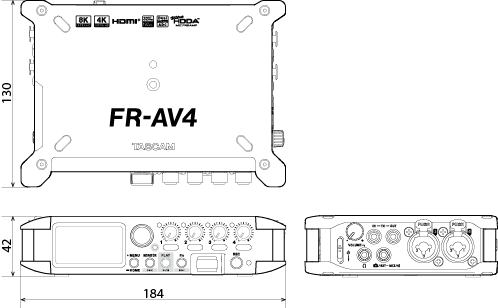
TASCAM is a registered trademark of TEAC Corporation.
SDXC Logo is a trademark of SD-3C, LLC.
![]()
The terms HDMI, HDMI High-Definition Multimedia Interface, HDMI trade dress and the HDMI Logos are trademarks or registered trademarks of HDMI Licensing Administrator, Inc.
![]()
Microsoft and Windows are either registered trademarks or trademarks of Microsoft Corporation in the United States and/or other countries.
Apple, Mac, macOS, iOS, iPad, iPadOS and iTunes are trademarks of Apple Inc. in the United States and other countries.
App Store is a service mark of Apple Inc.
Lightning is a trademark of Apple Inc.
IOS is a trademark or registered trademark of Cisco in the U.S. and other countries and is used under license.
Android and Google are trademarks of Google LLC.
The Bluetooth® word mark and logo are the property of Bluetooth SIG, Inc. and are used by TEAC Corporation with permission.
ASIO is a trademark and software of Steinberg Media Technologies GmbH.
![]()
Other company names, product names and logos in this document are the trademarks or registered trademarks of their respective owners.
|
0526.MA-4076C |
|