|
|
D01449020B |

SMPTE ST 2110 INTERFACE CARD
WebUI MANUAL
.jpg)
|
|
D01449020B |
SMPTE ST 2110 INTERFACE CARD
WebUI MANUAL
This card can be set and monitored by using an application that is accessed through a web browser.
(Hereafter, we will refer to this application as “WebUI”.)
This document explains how to operate this WebUI
Conventions used in this manual
In this manual, we use the following conventions:
 Digital audio data that is sent and received with this card through an IP network is called a “stream”.
With redundant systems, buffering is necessary to compensate for latency differences. These are called “buffer times”.
Additional information is introduced in the styles below when needed:
TIP
These are tips about how to use the card.
NOTE
These provide additional explanations and describe special cases.
ATTENTION
Failure to follow these instructions could result in damage to equipment or lost data, for example.
 CAUTION
Failure to follow these instructions could result in injury.
TASCAM is a registered trademark of TEAC Corporation.
Microsoft, Windows, Windows 10 and Windows Media are either registered trademarks or trademarks of Microsoft Corporation in the United States and/or other countries.
Google Chrome are trademarks of Google Inc.
Other company names, product names and logos in this document are the trademarks or registered trademarks of their respective owners.
Copyright and license information related to open source code is posted on the product page of our website.
https://tascam.jp/int/product/if-st2110/support
System that supports Google Chrome browser operation
Windows 10 or later
Intel Pentium 4 or newer processor
Compatible models for installation
Supported devices
Sonicview 16, Sonicview 24
Software versions
Sonicview units: V2.0*
*We highly recommend that you always use the latest firmware for the Sonicview unit. For the latest firmware, check the TASCAM website.
Sonicview 16
https://tascam.jp/int/product/sonicview_16/support
Sonicview 24
https://tascam.jp/int/product/sonicview_24/support
ATTENTION
When using this model installed in a Sonicview, only one of these cards can be used at a time.
If two cards are installed, only the one in SLOT 1 of the Sonicview can be used.
This chapter explains how to connect this card to a computer and access it using the WebUI.
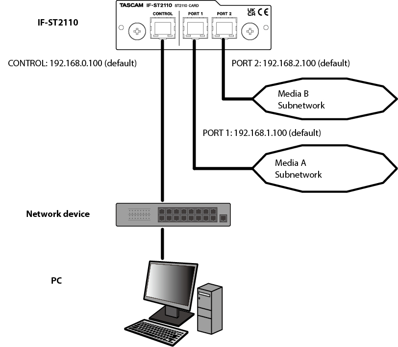
Prepare a computer and connect it to the CONTROL port on the card in order to access the WebUI.
If the CONTROL port of the card is already connected through a network device, connect a LAN cable so that the computer is on the same network.
To connect the computer and the CONTROL port one to one, connect the LAN cable to both devices.
ATTENTION
Make these connections after installing this card into a compatible model.
For details about installation, see the operation manual of the compatible model.
NOTE
For LAN cables used for connection, use STP cables that are category 5e or higher. (Both straight and crossover cables are supported.)
After completing connection, turn on the device that this card has been installed in.
Changing the IP address of the computer
To connect a computer to this card and access the WebUI, the IP address of the computer must be changed and it must operate on the same network as the CONTROL port of the card.
This section uses a Windows PC for examples.
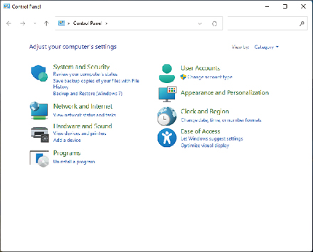
Open the Control Panel
1.Click the Windows button.
2.Search for and select the Control Panel.
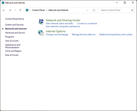
Open the Network and Sharing Center
1.Click Network and Internet.
2.Click Network and Sharing Center.
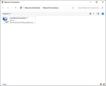
Open Change adapter settings
1.Click Change adapter settings in the left side menu.
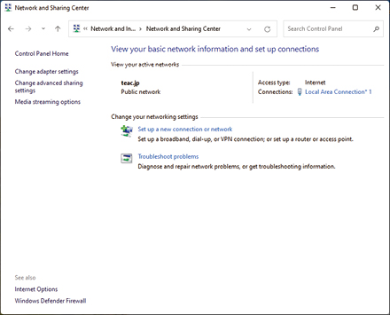
2.In the network connections list, right-click the network adapter being used (usually Ethernet), and select Properties.
Set the IP address
1.Select Internet Protocol Version 4 (TCP/IPv4), and click Properties.
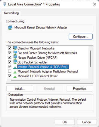
NOTE
This card does not use IPv6.
Put a check (![]() ) into the “IPv4” checkbox.
) into the “IPv4” checkbox.
2.Select “Use the following address”.
3.Input the following data.
 IP address: 192.168.0.50 (example)
Subnet Mask: 255.255.255.0
Default Gateway: blank
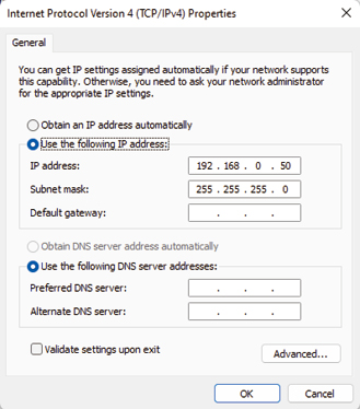
NOTE
The computer IP address can be set freely, but set it to meet the following conditions.
Locate it on the same subnetwork as the CONTROL port on the card.
Do not overlap with the IP address of the CONTROL port of the card.
Do not overlap with the IP addresses of other devices on the same network
Using the factory default settings of this card, the IP address of its CONTROL port is “192.168.0.100”.
In this case, set the computer IP address to a different value.
The above is a setting example when the card is using its factory default settings.
Apply the settings
1.Click the “OK” button to save the settings.
2.Click the Close buttons to close all the windows.
WebUI is controlled using a web browser.
Install the web browser in advance on the computer to be used.
NOTE
Google Chrome is the recommended browser. (see “Operating environment”.)
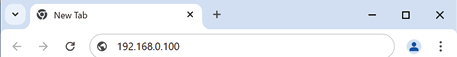
1.Open the web browser on the computer.
2.In the address bar, input the IP address of the card’s CONTROL port, and press the Enter key.
NOTE
The factory default value settings for the IP address of the CONTROL port are as follows.
IP Address: 192.168.0.100
Subnet Mask: 255.255.255.0
Gateway: 0.0.0.0
3.Open the WebUI for the card.
When the WebUI for the card is accessed, either a Wizard Screen or the Home Screen will open.
When the WebUI for the card is accessed for the first time in a factory default state, the Wizard Screen will open.
Various setting and management screens can be accessed from the Home Screen.
The illustration below shows the structure of the WebUI.
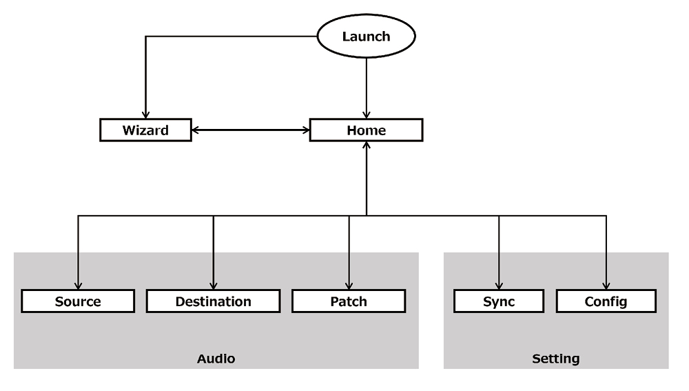
Wizard Screen (see “5 – Wizard Screen”.)
Make initial settings on this screen.
Home Screen (see “Home Screen”.)
The status of the card can be monitored on this screen.
The following screens can also be opened.
Working with audio routings
Patch Screen (see “Patch Screen”.)
Streams desired for reception can be visually routed.
Source Screen (see “Source Screen”.)
Streams transmitted from the card can be created and managed.
Destination Screen (see “Destination Screen”.)
Streams received by the card can be created and managed.
Changing and managing settings
Sync Screen (see “Sync Screen”.)
Settings can be made related to the card’s PTP and the status can be shown.
Config Screen (see “Config Screen”.)
Various card settings can be made and their states can be shown.
Procedures for enabling audio on the card
The minimum necessary procedures to enable audio on the card are as follows.
1. Basic settings
1-1. IP address change
Change the IP address of the card port according to the setup of the system being used.
See the following for change procedures.
5 – Wizard Screen: “3. IP Address for Control Port and NET Ports”
7 – Changing various settings: “PTP synchronization”
1-2. PTP synchronization
To transmit audio with this card and change settings, PTP (Precision Time Protocol) synchronization with the system being used is necessary.
See the following for change procedures.
5 – Wizard Screen:“6. PTP Timing System”
7 – Changing various settings: “PTP synchronization”
NOTE
We recommend operating this card as a PTP follower.
1-3. Startup Config
To transmit audio with this card and change settings, the “Startup Config” indicator must have become green.
See the following for details.
1-4. Codec settings
Set the sampling frequency and the packet time.
Two ways of setting are available.
5 – Wizard Screen: “7. Audio Packet Time” and “8. Audio Sampling Frequency”
7 – Changing various settings: “Changing the sampling frequency and packet time”
2. Enabling audio
2-1. Source stream creation
Set a source stream (audio data sent from this card to an external device).
7 – Changing various settings: “Creating source streams”
2-2. Destination stream creation
Set a destination stream (audio data received by this card from an external device).
7 – Changing various settings: “Creating source streams”
ATTENTION
After the power is turned on, this card needs about 2 1/2 minutes before it can input and output audio.
This time will vary according to the setup of the network connected to the card.
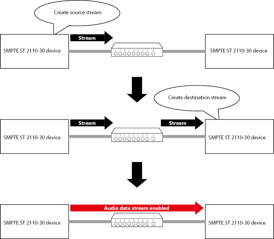
Overview of audio data transmission with this card
Since this card is compliant with SMPTE ST 2110-30, it can transmit and receive audio data in multicast format.
The transmission and reception of audio data is handled in units called “streams”.
A source stream must be created to send audio data, and a destination stream must be created to receive audio data.
To enable audio, use this WebUI to create source and destination streams.
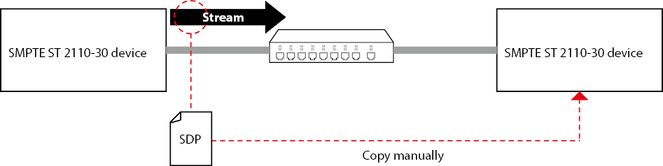
To create a destination stream manually, SDP data is necessary for the stream to be received.
SDP (Session Description Protocol) is a format that describes parameters for establishing transmission.
SDP data is unique to each stream.
Destination streams can be created by copying and pasting SDP data to this WebUI.
This chapter explains the Wizard Screen.
Initial settings for the card can be made on this screen.
To open the Wizard Screen from other screens, see “H Load Wizard button”.
.jpg)
This opens the Home Screen.
 Switching startup screen switch
Set this switch to “ON” to change the startup screen next time.
If the current startup screen is the Wizard Screen, the Home Screen will open next time.
If the current startup screen is the Home Screen, the Wizard Screen will open next time.
NOTE
When the WebUI for the card is accessed for the first time in a factory default state, the Wizard Screen will open.
After making initial settings the first time starting up, we recommend setting this to “ON”.
 Dark Mode switch
This switches the color theme used by this WebUI screen.
|
Option |
Meaning |
|
ON (default) |
Dark mode will be used for the WebUI design theme. |
|
OFF |
Light mode will be used for the WebUI design theme. |
 Reboot Device button
Click this button to restart the card.
ATTENTION
While restarting, access to WebUI will not be possible and audio data transmission will be interrupted.
If necessary, mute the device that this card is installed in.
NOTE
Restarting this card will not restart the device that it is installed in.
 Initial Setup Page area
Make initial settings for the card here.
Some of the initial setting items might already be set with correct values. Such settings do not need to be changed.
The card must be restarted in order to enable some of the initial setting items. Restarting once after making several changes will enable all of them. (Use the Reboot Device button () to the left.)
Detailed information can be shown by aligning the mouse cursor with the information/help button ( ![]() ) to the side of some items.
) to the side of some items.
NOTE
By clicking the Load WebUI button, a screen where more detailed settings and monitoring are possible can be accessed.
Input/edit the device name for the card in this area.
.jpg)
Input/edit the device name. (default: IF-ST2110)
NOTE
The device name set for the card might be shown on other devices and computers connected to the network.
Apply button
Save the edited device name.
The WebUI version can be checked in this area.
.jpg)
 Current Firmware Version
This shows the WebUI firmware version.
Example:
WebUI Version: v.1.0.0-b009
3. IP Address for Control Port and NET Ports
Make settings in this area for the CONTROL and media (PORT 1/2) ports on the card.
After changing settings, use the Update buttons to save them.
.jpg)
Control Port
Set the IP address of the CONTROL port on the card.
|
Item |
Content |
|
Mode |
Select “Static” or “Dynamic” for how the IP address is determined. (Default: Static) If “Dynamic” and there is a DHCP server on the network, the IP address will be acquired automatically. |
|
Static IP |
If the Mode item is set to “Static”, the input IP address will be used. (Default: 192.168.0.100) |
|
Subnet mask |
If the Mode item is set to “Static”, the input Subnet Mask will be used. (Default: 255.255.255.0) |
|
Gateway |
If the Mode item is set to “Static”, the input Gateway will be used. (Default: 0.0.0.0) |
PORT 1/PORT 2
Set the IP addresses of the media ports (PORT 1/2) on the card.
|
Item |
Content |
|
Mode |
Select “Static” or “Dynamic” for how the IP address is determined. (Default: Dynamic) If “Dynamic” and there is a DHCP server on the network, the IP address will be acquired automatically. |
|
Static IP |
If the Mode item is set to “Static”, the input IP address will be used. |
|
Subnet mask |
If the Mode item is set to “Static”, the input Subnet Mask will be used. |
|
Gateway |
If the Mode item is set to “Static”, the input Gateway will be used. |
NOTE
If the setting made following “5. Seamless Protection Switching” is “Enable”, PORT 1 and PORT 2 will be shown. If it is “Disable”, only PORT 1 will be shown.
This area shows the network connection states of the card’s PORT 1 and PORT 2.
.jpg)
Status display details
|
Status |
Meaning |
|
OK |
The network is functioning normally. |
|
Link is Down |
The network has been interrupted. Check “Problems with Ethernet connection” for details. |
NOTE
If the setting made following “5. Seamless Protection Switching” is “Disable”, the connection status of PORT 2 will not be shown.
5. Seamless Protection Switching
The SMPTE ST 2022-7 function can be enabled/disabled in this area.
Enable this when using this card in a redundant system.
.jpg)
SMPTE ST 2022-7 function setting
When enabled, both PORT 1 and PORT 2 on this card become usable.
When enabled, in compliance with SMPTE ST2022-7, switching between PORT 1 and PORT 2 on the card becomes possible.
|
Option |
Meaning |
|
Enable (default) |
This enables the SMPTE ST 2022-7 function. |
|
Disable |
This disables the SMPTE ST 2022-7 function. This setting will hide network data for PORT 2. |
Apply button
Click this button to save setting changes.
Use this area to make settings related to PTP synchronization.
.jpg)
This pull-down menu selects whether or not this card is always a PTP follower.
Set this to “Enable” if there is already a PTP master device on the network or you want to run this device fixed as a PTP follower.
|
Option |
Meaning |
|
Enable |
This card will always be a PTP follower and never become a PTP master in this mode. |
|
Disable (default) |
This card will become the PTP master when its PTP Priority value is the lowest on the network. |
NOTE
PTP synchronization has “One-step” and “Two-step” modes.
This card supports both “One-step” and “Two-step” modes. Normally, it will operate using Two-step mode, but if it is necessary to operate using One-step mode, set Follower Only to “Enable”.
Profile
This selects which PTP synchronization standard to use with this card.
Click this area to open a window where it can be selected.
|
PTP profile |
Description |
|
IEEE1588v2:Default |
PTP profile compliant with IEEE1588-2008 |
|
AES67:Media |
PTP profile compliant with AES67 |
|
SMPTE:2059-2(LEGACY) |
PTP profile compliant with SMPTE ST 2059-2: 2015 |
|
SMPTE:2059-2:2021 |
PTP profile compliant with SMPTE ST 2059-2: 2021 |
NOTE
PTP synchronization will not be possible if the PTP profile setting is different from the system being used.
Domain
This sets the PTP domain.
Range: 0 – 255
NOTE
PTP synchronization will not be possible if the domain value is different from the system being used.
Apply button
This saves the PTP settings changed for – above.
PTP parameters
This shows parameters related to PTP synchronization.
|
Item |
Meaning |
|
Master Lock Mode |
This shows the PTP master lock mode. |
|
Current Reference |
This shows the reference being used for PTP synchronization. INTERNAL OSCILLATOR: clock from the oscillator in the card PTP FOLLOWER: grandmaster clock on the network |
|
Interface Status |
This shows whether the media ports (PORT 1/2) are PTP synchronized or not. |
|
PTP Master ID |
This shows the identification number for the PTP grandmaster device on the network. This is shown in hexadecimal and includes the MAC address. |
|
Role Status |
This shows the PTP synchronization status of the media ports (PORT 1/2). Initializing: Preparation for PTP synchronization is not complete. Listening: PTP synchronization signals are being received and preparation for synchronization is complete. Uncalibrated: PTP synchronization signals are being received, but it is still not locked. Pre-Master: Trying to lock as a PTP master, but it is still not locked. Master: It is locked as a PTP master. Follower: It is locked as a PTP follower. Passive: PTP synchronization signals are being received, but it is not trying to synchronize using those signals. Faulty: PTP synchronization has not been possible. |
 Current State
This concisely shows the PTP synchronization state.
|
Item |
Meaning |
|
ACTING AS MASTER |
This card is operating as the master clock. |
|
SUCCESSFULLY LOCKED |
This card is operating as a PTP follower and is locked. |
|
ERROR |
PTP synchronization has not been possible. The cause could be that either the PTP master cannot be found or it is not set to a PTP domain shared with another device. In addition, confirm that the Follower Only function is set to “Disable” when making this card the master. |
Use this area to set the packet time.
.jpg)
Audio Packet Time
The audio data packet time can be selected.
Options: 1000 µs (default), 125 µs
Apply button
Click this button to save packet time setting changes.
NOTE
Limitations on the number of channels that can be included in a stream as well as the number of streams change according to the packet time setting.
See “Maximum codec and channel numbers” and “Maximum number of streams for this card” for details.
The audio sampling frequency can be changed in this area.
.jpg)
Audio Sampling Frequency
Select the sampling frequency.
Options: 44.1 kHz, 48 kHz (default), 88.2 kHz, 96 kHz
NOTE
Select the sampling frequency to match the device in which this card is installed and the connected system.
Apply button
Click this button to save sampling frequency setting changes.
NOTE
The sampling frequency must be set to the same value as that of other devices on the system in order to send and receive audio data with them.
The number of channels contained in each stream can be specified in this area.
This value is used when it is necessary for all streams to contain the same number of channels, as with NMOS (Networked Media Open Specifications), for example.
.jpg)
Audio Channel Count Mode
This selects the number of channels contained in each stream.
Click this area to open a window where it can be selected.
Options: Mixed, 1, 2, 4, 8 (default), 16 or 64 channels
Multiple source streams can be created at once in this area.
NOTE
Before using Bulk Sessions to create streams, confirm that all source streams have been deleted.
Bulk Sessions cannot be used to create streams if any streams have already been created.
.jpg)
Number of Streams
Input the number of streams to be created at the same time.
Up to 128 streams can be created with this card. (see “Maximum number of streams for this card”.)
Number of Channels Per Stream
Specify the number of channels per stream.
Note that the maximum will change according to the format settings.
See “Maximum codec and channel numbers” for details.
Session Name Prefix
Specify the first part of stream names. Input a name as desired.
NOTE
When streams are created, the characters input here will be used at the beginnings of the names of every stream, while the ends of the names will be numbered automatically.
Codec
Use this pull-down menu to select codecs.
Codec list
|
Codec |
Description |
|
Audio and Control (AM824 - Legacy) (default) |
Encoding will follow the stream format definitions of IEC 61883-6 and IEEE1394 (FireWire). |
|
AES67 (L32) |
Encoding will follow the stream format definitions of AES67 and use 32-bit depth. |
|
AES67 (L24) |
Encoding will follow the stream format definitions of AES67 and use 24-bit depth. |
|
AES67 (L16) |
Encoding will follow the stream format definitions of AES67 and use 16-bit depth. |
|
Audio and Control (AM824 - AES3 Transparent) |
Encoding will follow the stream format definitions of AM824 and include AES3 user bits. |
NOTE
Make settings for this card according to the Codec settings of the other devices in the system.
Add Bulk IP Streams button
Click this button to create multiple source streams with the content of – above.
This chapter explains the screens other than the Wizard Screen.
Use these screens to monitor the card and make specific settings.
The section explains common content shown on the screens.
.jpg)
Header
 TASCAM banner
Click this to open the TASCAM home page. (https://teac-global.com/)
 Bandwidth occupancy
This shows the sending and receiving network bandwidth occupancy separately for PORT 1 and PORT 2.
 Refresh WebUI button
Use this to reload all the content of the WebUI.
Click this whenever the WebUI settings or status of the connected network changes.
This area is shared by all screens except the Wizard Screen.
 Navigation links
These change what is shown in the content area ().
These show the status of the card.
|
Indicator |
Meaning |
|
Startup Config |
Green: Audio transmissions and setting changes are possible. Red: Audio transmissions and setting changes are not possible. If this does not become green after waiting several minutes, conduct PTP synchronization again or restart this WebUI. |
|
Reboot Indicator |
This will light yellow when it is necessary to restart the card. |
|
Global Alarm |
If there are abnormalities with operation or settings, this will appear red with the number of abnormalities. |
 Dark Mode switch
This switches the color theme used by this WebUI screen.
|
Option |
Meaning |
|
ON (default) |
Dark mode will be used for the design theme of WebUI. |
|
OFF |
Light mode will be used for the WebUI design theme. |
 Reboot Device button
Click this button to restart the card.
ATTENTION
While restarting, access to WebUI will not be possible and audio data transmission will be interrupted.
If necessary, mute the device that this card is installed in.
NOTE
Restarting this card will not restart the device that it is installed in.
Click this button to open the Wizard Screen.
Content area
This shows the linked screen selected by the navigation link ().
.jpg)
Sources area
This shows a list of streams being sent to the network.
Destinations area
This shows a list of streams being received by the card.
Session Details area
Clicking a stream name will show its SDP data on the right side of this WebUI Screen.
Copy SDP Information button
Click this button to copy the SDP data being shown to the clipboard.
Sources area () and Destinations area () details
PORT 1/2 connection states
These icons show the stream connection states of the media ports (PORT 1/2).
|
Appearance |
Connection state |
|
Green |
Good transmission state |
|
Orange |
Problem with connection |
|
Red |
Connection not achieved |
|
Number |
Number of problems |
|
Black mark |
LAN cable not connected |
NOTE
Hovering the mouse cursor over icons will show messages.
Stream type
These icons show stream types.
|
Icon |
Status |
|
LCL |
Stream being sent by this card |
|
RAV |
Stream being sent by another device |
|
SDP |
Stream created based on SDP data |
|
SAP |
Stream created with SAP (Session Announcement Protocol) mode set to “Enable” |
|
NMOS |
Stream created with NMOS |
State indicators
These show stream recognition states.
|
Appearance |
Status |
|
Green |
Stream is able to be received or sent |
|
Gray |
Stream is not able to be received or sent |
Stream deletion button
This deletes the destination stream.
ATTENTION
Clicking this button will immediately delete the destination stream.
Use caution because no confirmation will be shown before deletion.
Destination streams can be created visually on this screen.
.jpg)
Active Connections area
This shows destination streams that have already been routed.
ATTENTION
Clicking a Delete button will immediately cancel the routing and delete the destination stream.
Advertised streams
This shows streams being sent to the network. This is limited, however, to codecs that conform to the settings of this card.
Every 8 channels will be folded into 1 group.
Click the ![]() /
/![]() button to open/close the accordion menu.
button to open/close the accordion menu.
Card channel ports
This shows channels output from this card to the unit it is installed in.
Every 8 channels will be folded into 1 group.
Click the ![]() /
/![]() button to open/close the accordion menu.
button to open/close the accordion menu.
NOTE
The number of available channels will differ according to the sampling frequency setting.
|
Sampling frequency |
Available channels |
|
48 kHz |
Channels up to Output 64 in Group 8 |
|
96 kHz |
Channels up to Output 32 in Group 4 |
Matrix area
This shows the routing states of advertised streams () and the channel ports of this card () in a matrix format.
Select the stream channel to be received from the advertised streams () and select the channel or group to assign them to from the card’s channel ports (). Then, click the square in the grid where they intersect to link or unlink them.
Click the Apply button shown in the Stream display area () to apply changes to links.
Stream display area
This shows details about streams that have been linked in the matrix area ().
Click the Apply button to start stream reception.
Click the Clear button to remove the link.
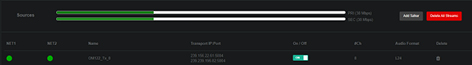
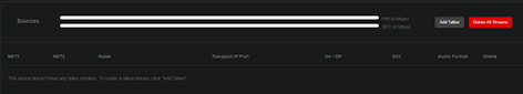
Source streams for the card can be created and managed on this screen.
.jpg)
Transmission bandwidth occupancy
This shows separately for PORT 1 and PORT 2 the amount of the card’s network bandwidth that is occupied by streams being transmitted.
Add Source button
Click this button to open the Add Source menu where source streams can be created. (see “Source Screen Add Source menu”.)
Delete All Streams button
Click this button to delete all source streams at once.
Source stream display area
The streams being transmitted by this card can be listed.
Link status indicators
Icons show stream connection states. (see “Stream connection states”.)
These are shown separately for PORT 1 and PORT 2.
Stream names
These are the names assigned to the streams.
Multicasting addresses
This shows the multicasting addresses and port numbers assigned to the streams.
These are shown separately for PORT 1 and PORT 2 in order from the top.
Activation buttons
These switch the stream activation states. Audio is sent when ON and not sent when OFF.
 Numbers of streaming channels
These show the numbers of audio channels contained in the streams.
Codecs
These show the audio codecs of the streams.
Delete buttons
Use these to delete streams.
ATTENTION
Clicking these buttons will immediately delete the destination streams.
Use caution because no confirmation will be shown before deletion.
Clicking a stream will open the Source information menu. (see “Source Screen Source information menu”.)
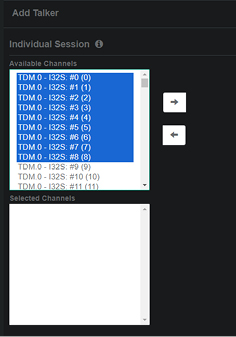
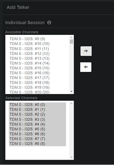
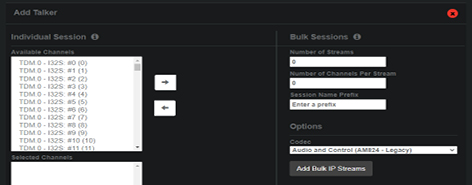
This menu can be used to create source streams.
.jpg)
 Channel settings area
Available Channels / Selected Channels
Select channels to patch to the source stream.
Click a channel name and click the right arrow button to the right of the Available Channels field to select/deselect that channel.
NOTE
By pressing the computer keyboard Ctrl key, multiple channels can be clicked and selected.
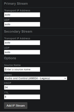
 Address settings area
Specify multicasting addresses and port numbers of streams here.
If they are not specified, they will be assigned automatically if “auto” is input.
 Stream settings area
Source Name
Set the stream name.
Codec
Set the stream audio codec.
DSCP
This value is used for network traffic classification and management. The default value is “34” which corresponds to the DSCP name of “AF41”.
When changing this value, follow the instructions of the administrator of the network being connected to.
TTL
This is a timeout value to prevent packets with unclear addresses from continuing to remain on the network.
When connecting to a large-scale network, change this as necessary.
When changing this, however, follow the instructions of the administrator of the network being connected to.
Payload Type
This is an identifier for distinguishing data transmitted by RTP packets.
 Add IP Stream button
Click this button to create a source stream with the above settings.
 Bulk Sessions area
Multiple source streams can be created at once by setting the items in this area.
See “10. Bulk Sessions” in the Wizard Screen section for details about these settings.

![]() button
button
Click this button to close the Add Source menu.
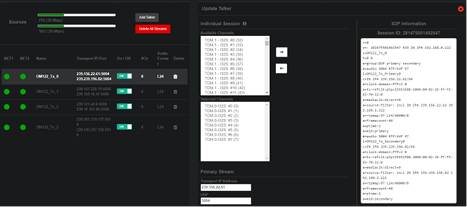
Source Screen Source information menu
In this menu, source stream settings clicked on the Source Screen can be checked and changed.
.jpg)
 Update Source button
This applies changes made on the Source Screen Add Source menu in the channel settings (), address settings () and stream settings () areas.
 SDP Information area
SDP data for the selected source stream is shown here.
The session ID is shown outside the field.

![]() button
button
Click this button to close the Source information window.
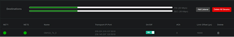
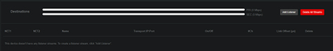
Destination streams for the card can be created and managed on this screen.
.jpg)
Receiving bandwidth occupancy
This shows separately for PORT 1 and PORT 2 the amount of the card’s network bandwidth that is occupied by streams being received.
Add Destination button
Click this button to open the Add Destination menu where destination streams can be created. (see “Destination Screen Add Destination menu”.)
Delete All Streams button
Clicking this button will immediately delete all destination streams. A confirmation dialog will appear before they are deleted.
Destination stream display area
The streams being transmitted by this card can be listed.
Link status indicators
Icons show stream connection states. (see “Stream connection states”.)
These are shown separately for PORT 1 and PORT 2.
Stream names
These are the names assigned to the streams.
Multicasting addresses
This shows the multicasting addresses and port numbers assigned to the streams.
These are shown separately for PORT 1 and PORT 2 in order from the top.
Activation buttons
These switch the stream activation states. Audio is received when ON and not received when OFF.
Numbers of streaming channels
These show the numbers of audio channels contained in the streams.
Buffer times
These are the stream buffer time settings. The unit is µs (microseconds).
Stream deletion buttons
Use these to delete streams.
ATTENTION
Clicking this button will immediately delete the destination stream.
Use caution because no confirmation will be shown before deletion.
Clicking a stream will open the Update Destination menu. (see “Destination Screen Update Destination menu”.)
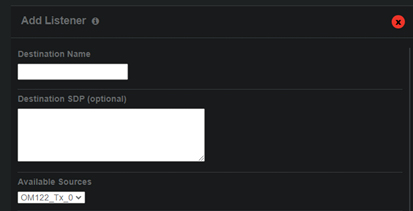
Destination Screen Add Destination menu
This menu can be used to create destination streams.
.jpg)
Destination Name
Specify the name of the created destination stream.
Destination SDP (optional)
Input SDP data here and change the settings of the selected destination stream.
Channel selection area
Available Sources
Use this pull-down menu to select the stream to receive.
NOTE
If “Ravenna Adv. Mode” is disabled on the Connection Configuration page of the Config Screen, streams will not be shown in this menu. In this case, manually copying SDP data to Destination SDP (optional) () will be necessary.
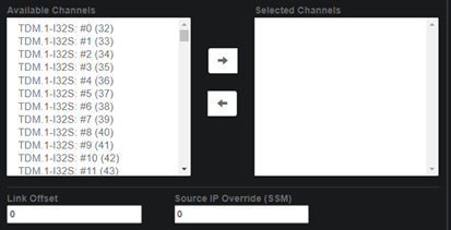
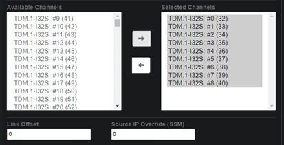
Available Channels / Selected Channels
Select channels to patch to the destination stream.
Click a channel name and click the right arrow button to the right of the Available Channels field to select/deselect that channel.
NOTE
By pressing the computer keyboard Ctrl key, multiple channels can be clicked and selected.
Destination stream setting area
Buffer time and SSM (Source-Specific Multicast) settings can be made here.
Add Destination button
Click this button to create a destination stream with the above settings.
![]() button
button
Click this button to close the Add Destination menu.
Destination Screen Update Destination menu
This menu can be used to check and change destination stream data.
.jpg)
Destination stream name
Use this to change the name of the selected destination stream.
Channel selection area
This shows which of the card’s channels the received destination streams are assigned to.
 Link Offset setting area
Set the buffer time here.
See “Changing the buffer time” for setting procedures.
 Update Destination button
This applies stream setting changes using the above Destination stream name () and Link Offset setting area () content.
 SDP Information area
SDP data for the selected destination stream is shown here.
The session ID is shown outside the field.

![]() button
button
Click this button to close the Update Destination menu.
The PTP settings and status can be shown on the Sync Screen.
Since PTP synchronization is indispensable for operation of this card, use this screen to confirm that it is locked properly.
This card can be both a PTP master and a PTP follower. In addition, this card can also be forced to always be a PTP follower.
.jpg)
Global PTP Configuration
Profile
Select the PTP profile to use.
For a list of PTP profiles that can be selected, see “PTP profile list”.
Follower Only
Set whether or not this card is always a PTP follower.
See “1 Follower Only” for details.
Apply button
This saves the PTP profile and the Follower Only setting.
Domain
This sets the PTP domain number of the system being connected.
Setting range: 0 – 255
Priority 1/Priority 2
These values are used to evaluate whether or not this card should be made the PTP master within the system being used.
Priority 1 setting range: 0 – 255 (default: 128)
Priority 2 setting range: 0 – 255 (default: 128)
NOTE
The lower the value is, the higher the preference is for the card to become the PTP master.
Priority 1 is prioritized over Priority 2.
If another device in the system being used has the same Priority 1 value as this card, the one with the lower priority 2 value will have precedence to become the PTP master.
Apply button
This saves the PTP domain and Priority 1/2 settings.
PTP synchronization interval setting
By setting the following items, the PTP synchronization message interval can be adjusted.
For each PTP profile, specific PTP synchronization intervals are defined.
This card will automatically change the setting to the recommended value for the specified PTP profile, but this can later be changed to any value.
These settings can also be set differently for PORT 1 and PORT 2 as needed.
Sync Interval
This sets the transmission interval of synchronization messages from the PTP master device to PTP follower devices on the network.
Options: 62.5 ms, 125 ms (default), 250 ms, 500 ms, 1 s, 2 s
Announce Interval
This sets the interval at which a PTP master device on the network transmits announce messages, which include its status related to PTP, its priority and other information.
Options: 250 ms, 500 ms, 1 s, 2 s (default), 4 s, 8 s
Announce Receipt Timeout
This sets the amount of time until a PTP follower device treats it as a timeout if it does not receive an announce message from a PTP master device.
Range: 0 – 255 (default: 3)
|
Status items |
Meaning |
|
System Status |
This shows whether the PTP processing system of this card is PTP synchronized or not. |
|
Interface Status |
See the “PTP parameter list”. |
|
Current Reference |
See the “PTP parameter list”. |
This shows status related to PTP synchronization.
|
Status items |
Meaning |
|
Grandmaster ID |
See the PTP Master ID item in the “PTP parameter list”. |
|
Grandmaster Priority 1 |
This shows the first priority parameter of the PTP master device. |
|
Grandmaster Priority 2 |
This shows the second priority parameter of the PTP master device. |
|
Offset From Master |
This shows the amount of discrepancy between the internal clock of this card and the PTP master clock. This is the difference between the PTP synchronization time of the card and the time recorded in PTP synchronization signals. |
|
Mean Path Delay |
This is the average time of transmission latency between the PTP master and the PTP follower. This is half the time required for a round-trip after arriving at the PTP follower from the PTP master and then returning to the PTP master. |
|
Clock Accuracy |
This indicator evaluates the temporal error of the clock precision. |
|
Local ID |
This shows the identification numbers of the media ports (PORT 1/2). This is shown in hexadecimal and includes the MAC address. |
|
State |
See the Role Status item in the “PTP parameter list”. |
|
Delay Mechanism |
This shows the measurement method for delay between devices on the network. |
|
Sync Interval |
This shows the current sync interval value. |
|
Announce interval |
This shows the current announce interval value. |
|
Announce Receipt Timeout |
This shows the current announce receipt timeout value. |
PTP Offset from Master Graph
This shows the amount of discrepancy between the internal clock of this card and the PTP grandmaster clock as a graph.
The horizontal axis is the elapsed time and the vertical access is the amount of discrepancy shown in units of nanoseconds (1 billionth of a second). The leftmost data is the newest.
The data is updated every 10 seconds. To reflect this in the graph, manually update it by clicking the Refresh Graph button.
If the Auto Refresh switch is “ON”, the graph will update automatically.
Click the RAW Offset button to change the graph calculation method to raw numbers.
Click the RMS Avg button to change the graph calculation method to the average value since startup.
The status of the card is shown and settings can be changed on the Status page.
.jpg)
Device Status
The status of the card is shown in this area.
Connection Settings
|
NMOS: |
This shows the NMOS setting status. |
|
SSM Mode: |
This shows the SSM Mode setting status. |
|
SAP Mode: |
This shows the SAP (Session Announcement Protocol) mode setting status. |
|
Ravenna Advertisement Mode: |
This shows the Ravenna Advertisement Mode setting status. |
|
Aneman Mode: |
This shows the Aneman Mode setting status. |
|
TCP Ports: |
The TCP port number setting states are shown for Ember+, Ravenna and RTSP. |
|
Ember+: |
|
|
Ravenna: |
|
|
RTSP: |
Audio Settings
|
Packet Time: |
This shows the packet time. |
|
SMPTE ST-2022-7 / Seamless Protection Switching: |
This shows the setting state of the SMPTE ST 2022-7 function. |
|
Link Offset Multiple: |
This shows the buffer time value. |
|
Channel Count Mode: |
This shows the number of channels contained in each stream. |
|
Channel Sampling Frequency: |
This shows the sampling frequency. |
Board Information
|
Product: |
This shows the device name. |
|
FW Date: |
These show information about the WebUI version. |
|
FW Version: |
|
|
FPGA Version: |
|
|
WebUI Version: |
NOTE
Information about the version of the card itself is not shown in this WebUI. To check the version information of this card, follow the operation procedures of the device that it is connected to.
IP Address Status
This shows the network setting status of the card.
Make settings related to audio transmission on the Audio Configuration page.
.jpg)
Global Audio Configuration
Make settings for the card, including its sampling frequency, settings related to audio compliant with SMPTE ST 2110-30 and settings related to SMPTE ST 2022-7 functionality.
ATTENTION
Changing settings on this page will delete audio streams that have already been created.
Channel Sampling Frequency
Use this pull-down menu to set the sampling frequency.
Options: 44.1 kHz, 48 kHz (default), 88.2 kHz, 96 kHz
ATTENTION
Changing the sampling frequency will delete all source and destination streams.
NOTE
When using this with a Sonicview, set it to 48 kHz or 96 kHz to match the system.
Match the setting with the sampling frequency of the connected network and operate it using that.
Packet Time
Use this pull-down menu to set the packet time.
Options: 1000 µs (default), 125 µs
ATTENTION
Changing the packet time will delete all source and destination streams.
Link Offset Multiple
This changes the buffer time when receiving streams. This is the time until received packets are returned to audio data.
For example, if the packet time is 1000 µs and this value is set to 3, the packet time will become 3 ms.
Channel Count Mode
For NMOS and other operations that require fixed channels, the number of channels in each IP stream can be selected.
Options: Mixed, 1, 2, 4, 8 (default), 16 or 64
SDP Source Interface
The Ethernet port used as the source for SDP files can be selected.
Options: Control (default), PORT 1, PORT 2
Apply button ()
Click the Apply button () to confirm the above changed settings.
Seamless Protection Switching
The SMPTE ST 2022-7 function can be enabled/disabled. (see “5. Seamless Protection Switching”.)
Options: Enable (default), Disable
Click the Apply button () to confirm the changed setting.
Make network connection settings for this card on the Connection Configuration page.
.jpg)
Advertisement Configuration
Make advertisement function settings in the Advertisement Configuration section.
SAP Mode
Set whether SAP (Session Announcement Protocol) mode is enabled or disabled.
When enabled, this card can announce and detect Dante AES67 streams generated with SAP.
Options: Enable, Disable (default)
Click the Apply button to confirm the changed setting.
Ravenna Adv. Mode
Enable/disable Ravenna advanced mode.
When enabled, this card can announce and detect Ravenna streams generated with SAP.
Options: Enable (default), Disable
Click the Apply button to confirm the changed setting.
Ravenna Board Name
This is the device name used to advertise Ravenna streams.
To change this, open the Wizard Screen and edit the device name (“1. Device Name”).
NOTE
Advertisement is a system for announcing and discovering session and device information on a network.
By using this system, other devices and services on the network can receive this information, ensure interoperability and automatically make settings.
NMOS Configuration
Make settings for setting and monitoring this card from connected NMOS control devices within the network.
NMOS Mode
When this is enabled, detection, registration and control of devices that are compliant with NMOS specifications are possible.
Options: Enable, Disable (default)
Advertised Receiver Channel Size
This shows the maximum number of channels per stream when receiving streams using NMOS.
Device Name
This shows the device name of the card that can be seen from nodes that are compatible with NMOS.
NOTE
The device name can be edited on the Wizard Screen. (see “1. Device Name”.)
Node Port
Set the number of the external node when this card connects with nodes that are compatible with NMOS.
Connection Port
Set the port number of this card when it connects with nodes that are compatible with NMOS.
Registry Service Discovery
Select the mechanism for detecting RDS (Registration and Discovery System). RDS uses NMOS and is a system for managing the discovery and registration of devices and services on a network.
Options: Automatic (default), Manual
NOTE
When “Manual” is selected, the screen below will appear.
.jpg)
Registry Service Address
Input the IP address of the NMOS server.
Registry Service Port
Input the port number for the NMOS server.
Registry API Version
Use this to select the NMOS version.
Options: V1.1, V1.2, V1.3 (default)
Misc. Configuration
Set the SSM Mode and Aneman Mode for the card.
SSM (Source-Specific Multicast), which is a stream reception method, can be enabled.
Use this when the connected network uses IGMPv3.
Options: Enable, Disable (default)
Aneman Mode
Set the ANEMAN control mode.
|
Aneman Mode |
Description |
|
Receivers Only Mode (default) |
This limits the control extent of this card using ANEMAN to destination streams. Use this WebUI to create source streams. |
|
Dual Group Receivers |
This limits the control extent of this card using ANEMAN to destination streams, but input and output name changes are possible. |
|
Full Duplex |
This makes the control extent of this card using ANEMAN include both source and destination streams. |
NOTE
ANEMAN, which was created by Merging Technologies and Digigram, is an audio network connection monitoring and management system application. It can be downloaded for free from the homepage of Merging Technologies.
https://www.merging.com/products/aneman/downloads
Depending on the ANEMAN version, one-to-many connections might not be supported, and source streams will be duplicated to the same number as there are reception nodes. In this case, this can be prevented by using the “Receivers Only Mode” setting, which limits the control extent of this card using ANEMAN to destination streams.
The firmware can be updated for this WebUI and the IP address, subnet mask and gateway can be set on the Board Configuration page.
.jpg)
Save Active Configuration button
This saves the card settings.
After clicking this button, settings will be applied when this card is restarted.
View Device Settings button
Click this button to open a window on this screen where the current settings of this unit are shown in JSON format.
Advanced Options button
This will show the following buttons to restore this card to default settings.
Clicking it again will hide them.
Reset to Initial Config button
This will restore the following settings on the Config Screen to their default values.
Sampling frequency
Packet time
This will restore the following settings on the Sync Screen to their default values.
Domain
Priority 1/2
Sync Interval
Announce Interval
Announce Receipt Timeout
This will delete the streams on the Source Screen and Destination Screen.
Reset to Factory Defaults button
This adds the following operations to the Reset to Initial Config button.
This will set all settings on the Connection Configuration page of the Config Screen to their default values.
This will restore the settings on the Sync Screen to their default values.
This will delete the streams on the Source Screen and Destination Screen.
This will restart the card automatically.
Device Management
This shows information about the WebUI version.
|
Product: |
This shows the device name. |
|
FW Date: |
These show information about the WebUI version. |
|
FW Version: |
|
|
FPGA Version: |
|
|
WebUI Version: |
NOTE
Information about the version of the card itself is not shown in this WebUI. To check the version information of this card, follow the operation procedures of the device that it is connected to.
Click the Update Firmware button to open the update screen for this WebUI.
For details about using the update screen, see the separate WebUI update manual.
ATTENTION
Only updater files provided by TASCAM can be used to update this WebUI. Updating with any other file will make this WebUI and the card inoperable. Do not update using anything other than an updater provided by TASCAM.
Use the Upgrades item to enable/disable the Update Firmware button.
Options: Enable, Disable (default)
IP address editing area
The IP address settings of the three ports on this card can be changed.
They can be changed individually for each port with their Update buttons.
After clicking an Update button, restart the card to apply the changes.
See “3. IP Address for Control Port and NET Ports” for details.
The operation of this card can be checked on the Troubleshooting page.
NOTE
To enable the Troubleshooting page, set the Upgrades item on the Board Configuration page to “Enable”.
.jpg)
List of generated files
Clicking the Packet Capture () and Request Debug () buttons below will generate packet capture files or compressed log data files, and the names and sizes of those files will be shown here.
|
|
Clicking this button will download the file. |
|
|
Clicking this button will delete the file. |
ATTENTION
Clicking the ![]() button will delete the file right away. Use caution because no confirmation will be shown before deletion.
button will delete the file right away. Use caution because no confirmation will be shown before deletion.
If a packet capture file is downloaded faster than the number of seconds designated in Duration [S]: (), the file might be broken. To download an unbroken file, refresh the browser multiple times, and wait for the capacity of the desired file to stop changing.
Packet Capture button
Click this button to start packet capture.
Capturing will start anew each time this button is clicked.
After the number of seconds input into Duration [S]: () has elapsed, capture will end automatically.
The capture results will be generated as a file in pcap format.
Duration [S]
This specifies the number of seconds until capture ends after pressing the Packet Capture button ().
If you want to change this value, complete input before pressing the Packet Capture button ().
Setting range: 1 – 300 (default: 30)
Interface
Select the desired port on the card to use for packet capture.
|
Option |
Meaning |
|
eth0 |
Control |
|
eth1 |
PORT 1 |
|
eth2 |
PORT 2 |
Request Debug button
Clicking this button will generate a log of operations since the card was started as a compressed file.
If the IP address of a port on this card duplicates that of another on the connected network, use the following procedures to change it.
1.Access the WebUI and open the Home Screen.
If the Wizard Screen opens, click the Load WebUI button to open the Home Screen. (see “Home Screen”.)
2.Click “Config” in the sidebar to open the Config Screen.
3.Click the Board Configuration tab to open the Board Configuration page. (see “Board Configuration page”.)
4.Change the IP address in the IP address editing area ().
If “Dynamic” is selected in the Mode field, click the Update button without further changes.
If “Static” is selected in the Mode field, input the Static IP, Static Mask and Gateway before clicking the Update button for the changed port.
5.If a dialog appears, the card must be restarted. Click the Reboot Device button in the sidebar to restart the power of the device in which this card is installed.
6.After restarting, access this WebUI using the changed IP address. Access will not be possible using the previous unchanged IP address.
Almost all the functions of this card, including audio transmission and network communication can only be used and set when PTP is synchronized.
The following procedures are the minimum required to establish PTP synchronization.
Additional settings might be necessary depending on the setup being used.
For details, along with referring to this document, please contact the administrator of the network being used.
NOTE
We recommend operating this card as a PTP follower.
When making this card a PTP follower
1.Referring to “Connecting the card”, wire this card suitably to the network being used.
2.After confirming that a PTP master device on the subnetwork is operating stably, start this card.
3.Access the WebUI and open the Home Screen.
If the Wizard Screen opens, click the Load WebUI button to open the Home Screen. (see “Home Screen”.)
4.In the Home Screen sidebar (), confirm that the status indicators () for Startup Config and Global Alarm are green. (see “2 Sidebar”.)
5.Open the WebUI Sync Screen. (see “Sync Screen”.)
6.In Global PTP Configuration () on the Sync Screen, select the same PTP protocol as the external device. Then, click the Apply button and refresh the browser.
For a list of PTP profiles that can be selected, see “PTP profile list”.
NOTE
When operating this card only as a PTP follower, we recommend enabling the Follower Only setting.
To enable Follower Only, after switching the Follower Only item to “Enable” in the Global PTP Configuration () of the Sync Screen, click the Apply button and refresh the browser.
7.In ETH Port PTP Configuration () on the Sync Screen, input values for the Domain, Priority 1 and Priority 2 items. Then, click the Apply button and refresh the browser.
See “2 ETH Port PTP Configuration” for details about what to input.
8.Check the PTP synchronization state of the card.
System Clock Status area (see “4 System Clock Status”.)
State item in PTP Lock Status area (see “5 PTP Lock Status”.)
9.Operate the screen on the device that this card is installed in, and change the Clock Master setting to this card.
ATTENTION
When using this card to send and receive audio, always set this card as the Clock Master of the device that this card is installed in.
If not set this way, noise could occur in the audio and operation could become unstable.
When using this card with a Sonicview, always select this card for the Clock Master setting.
When making this card a PTP master
1.Referring to “Connecting the card”, wire this card suitably to the network being used.
2.Turn on the device that this card has been installed in, and start this card.
3.Access the WebUI and open the Home Screen.
If the Wizard Screen opens, click the Load WebUI button to open the Home Screen. (see “Home Screen”.)
4.In the Home Screen sidebar (), confirm that the status indicators () for Startup Config and Global Alarm are green. (see “2 Sidebar”.)
5.Open the WebUI Sync Screen.
6.In Global PTP Configuration () of the Sync Screen, select the same PTP protocol as the external device. Then, click the Apply button and refresh the browser. (see “Sync Screen”.)
For a list of PTP profiles that can be selected, see “PTP profile list”.
7.In ETH Port PTP Configuration () on the Sync Screen, input values for the Domain, Priority 1 and Priority 2 items. Then, click the Apply button and refresh the browser.
See “2 ETH Port PTP Configuration” for details.
8.Check the PTP synchronization state of the card.
System Clock Status area (see “4 System Clock Status”.)
State item in PTP Lock Status area (see “5 PTP Lock Status”.)
9.Operate the screen on the device that this card is installed in, and change the Clock Master setting to this card.
ATTENTION
When using this card to send and receive audio, always select this card for the Clock Master setting of the device that this card is installed in.
If not set this way, noise could occur in the audio and operation could become unstable.
10.Start devices that will be PTP followers on the subnetwork, and confirm that PTP follower status is activated.
Changing the sampling frequency and packet time
1.Access the WebUI and open the Home Screen.
If the Wizard Screen opens, click the Load WebUI button () to open the Home Screen. (see “Home Screen”.)
2.Click “Config” in the sidebar to open the Config Screen. (see “Config Screen”.)
3.Click the Audio Configuration tab to open the Audio Configuration page. (see “Audio Configuration page”.)
4.Select the sampling frequency for the Channel Sampling Frequency item.
5.Select the packet time for the Packet Time item.
6.Click the Apply button.
NOTE
If a dialog appears, the card must be restarted. Click the Reboot Device button in the sidebar to restart the power of the device in which this card is installed.
If an error appears and the setting cannot be changed, see “Audio Configuration page”.
ATTENTION
Changing the sampling frequency or packet time will delete all source and destination streams.
Making audio stream transmission and reception settings
This explains the procedure to create source streams for this card.
1.Access the WebUI and open the Source Screen. (see “Source Screen”.)
If the Wizard Screen opens, click the Load WebUI button to open the Home Screen (see “1 Load WebUI button”.) and move to the Source Screen using the link in the sidebar.
2.Click the Add Source button () to open the Add Source menu. (see “Source Screen Add Source menu”.)
3.In the channel settings area () select the channels that you want to patch to the source stream.
Use the arrow buttons right of the Available Channels field to add and remove them.
NOTE
Multiple channels can be selected by pressing the computer keyboard Ctrl key while clicking channels that you want to patch to the source stream.
The number of channels that can be included in a stream has a maximum limit. (see “Maximum codec and channel numbers”.)
The maximum output of this card is 64 channels, so no more than 64 can be selected.
4.Input the desired name for the source stream that will be created in the Source Name field in the stream settings area ().
5.Set the stream audio codec with the Codec item in the stream settings area ().
6.Click the Add IP Stream button () to create the source stream.
After creating the source stream, click the  button () to close the Add Source menu.
7.Refresh the browser.
8.Confirm that the desired stream has been created in the source stream display area () of the Source Screen.
9.By clicking any stream and opening the Source information menu, stream settings can be checked in the SDP Information area.
This explains procedures to manually receive streams using this WebUI.
Consult with your network administrator for procedures to receive streams to this card remotely using NMOS, for example.
1.Make a note of the SDP data for the stream you want to receive.
2.Access this WebUI and open the Destination Screen. (see “Destination Screen”.)
If the Wizard Screen opens, click the Load WebUI button () to open the Home Screen (see “1 Load WebUI button”.) and move to the Destination Screen using the link in the sidebar.
3.Click the Add Destination button () to open the Add Destination menu. (see “Destination Screen Add Destination menu”.)
4.Input the desired name for the destination stream that will be created in the Destination stream name field ().
5.Input the text of the SDP data noted in step 1 into the Destination SDP field ().
NOTE
If the Ravenna Adv. Mode item is set to “Enable” on the Connection Configuration page of the Config Screen, streams to be received can be selected from the Available Sources item in the Add Destination menu, so inputting the Destination SDP (optional) () can be skipped. (see “Destination Screen Add Destination menu”.)
6.Select the channels that you want to patch to the Destination stream in the Available Channels field of the channel selection area ().
Use the arrow buttons right of the Available Channels field to add and remove them.
NOTE
Multiple channels can be selected by pressing the computer keyboard Ctrl key while clicking channels that you want to patch to the source stream.
ATTENTION
If a number is selected that differs from the number of channels contained in received streams, an error will occur and a stream will not be created.
7.Click the Add Destination button to create the destination stream.
After creating a stream, click the button to close the Add Destination menu.
8.Refresh the browser.
9.Confirm that the desired stream has been created in the destination stream display area of the Destination Screen.
10.Click any stream and open the Update Destination menu. Then, check the stream settings in the SDP Information area.
Creating multiple source streams with bulk processing
This explains the procedures to use the Bulk Sessions area in the Add Source menu of the Source Screen to create multiple source streams at once.
1.Access the WebUI and open the Source Screen. (see “Source Screen”.)
If the Wizard Screen opens, click the Load WebUI button () to open the Home Screen (see “1 Load WebUI button”.) and move to the Source Screen using the link in the sidebar.
2.Click the Add Source button () to open the Add Source menu.
3.Input the number of streams to create in the Number of Streams field.
4.Input the number of channels contained in each stream in the Number of Channels Per Stream field.
5.Specify the first part of stream names. Input a name as desired in the Session Name Prefix field.
NOTE
When streams are created, the characters input here will be used at the beginnings of the names of every stream, while the ends of the names will be numbered automatically.
6.Set the stream audio codec with the Codec item.
7.Click the Add Bulk IP Streams button to create them in bulk.
8.Refresh the browser.
9.Confirm that the desired stream has been created in the source stream display area of the Source Screen.
10.Click any stream and open the Source information menu to check stream settings in the SDP Information area.
ATTENTION
Creating multiple source streams with bulk processing is possible only when all the following conditions are met.
All source streams have been deleted
The bit depth, sampling frequency, packet time and number of channels are values that fit in one stream
The number of streams being created does not exceed the maximum for this card (see “Maximum codec and channel numbers”.)
Creating destination streams on the Patch Screen
Destination streams can be created and removed visually on the Patch Screen. (see “Patch Screen”.)
This explains the procedure for creation.
1.Determine the stream that you want to receive from the rows in the advertised stream area () on the Patch Screen.
2.Determine the channels or groups of channels that you want to assign from the channel port columns () for this card.
3.In the matrix area () of the Patch Screen click the intersecting squares.
Stream information will appear in the stream display area () on the Patch Screen.
4.Click the Apply button.
If the destination stream is created correctly, stream data will be shown in the Active Connections area ().
This completes destination stream creation.
1.Open the Source Screen. (see “Source Screen”.)
2.Click the Delete button for the source stream that you want to delete.
ATTENTION
Clicking will delete it immediately.
3.Refresh the browser.
4.If the deleted stream has disappeared from the source stream display area, deletion is complete.
NOTE
If the change is not reflected immediately, refresh the browser again after waiting a few seconds.
1.Open the Destination Screen. (see “Destination Screen”.)
2.Click the Delete button for the destination stream that you want to delete.
ATTENTION
Clicking will delete it immediately.
3.Refresh the browser.
4.If the deleted stream has disappeared from the destination stream display area, deletion is complete.
NOTE
If the change is not reflected immediately, refresh the browser again after waiting a few seconds.
After destination streams are created, their buffer times can be changed individually.
1.Open the Destination Screen. (see “Destination Screen”.)
2.Click the name of the desired stream for buffer time changing to open the Update Destination area.
3.Input the desired value in the Link Offset field. The range of values that can be input is restricted. (see “Buffer time adjustment range”.)
4.Click the Update Destination Button.
This will refresh the browser.
5.Look at the Link Offset field in the destination stream display area and confirm that the buffer time for the stream changed as desired.
Maximum codec and channel numbers
In SMPTE ST 2110-30, which this card complies with, the size of audio data in a single stream is limited to 1440 bytes.
This audio data size, which is the RTP payload length in Ethernet frames, is determined with the following formula.
|
Payload Length = |
B |
× S × |
P |
× C |
(Formula-1) |
|
8 |
106 |
The parameters in this formula are as follows.
B: Bit depth [bit] (examples: 16, 24, 32)
S: Sampling frequency [Hz] (examples: 44100, 48000, 96000)
P: Packet time [µs] (examples: 125, 1000)
C: Number of channels per stream
Before creating a stream, set B, S, P and C so that “Payload Length” does not exceed 1440.
Alternatively, determine the number of channels per stream (C) based on the requirements (B, S, P) of the network system being built.
This card, however, has a maximum number of channels per stream (C), which is 64 when the sampling frequency is 48 kHz or 32 when 96 kHz.
The following table lists ranges of channel numbers per stream for each codec in accordance with the SMPTE ST 2110-30 Conformance Level.
|
AES67 (L16/L24) AM824 (Legacy/AES3 Transparent) |
SMPTE LEVEL |
|||||
|
Sampling frequency, packet time |
A |
AX |
B |
BX |
C |
CX |
|
48 kHz, 1 msec |
1 to 8 channels |
1 to 8 channels |
1 to 8 channels |
1 to 8 channels |
1 to 8 channels |
1 to 8 channels |
|
48 kHz, 125 usec |
1 to 8 channels |
1 to 8 channels |
1 to 64 channels |
1 to 64 channels |
||
|
96 kHz, 1 msec |
1 to 4 channels |
1 to 4 channels |
1 to 4 channels |
|||
|
96 kHz, 125 usec |
1 to 8 channels |
1 to 32 channels |
||||
|
AES67 ( L32) |
SMPTE LEVEL |
|||||
|
Sampling frequency, packet time |
A |
AX |
B |
BX |
C |
CX |
|
48 kHz, 1 msec |
1 to 7 channels |
1 to 7 channels |
1 to 7 channels |
1 to 7 channels |
1 to 7 channels |
1 to 7 channels |
|
48 kHz, 125 usec |
1 to 8 channels |
1 to 8 channels |
1 to 60 channels |
1 to 60 channels |
||
|
96 kHz, 1 msec |
1 to 3 channels |
1 to 3 channels |
1 to 3 channels |
|||
|
96 kHz, 125 usec |
1 to 8 channels |
1 to 30 channels |
||||
Maximum number of streams for this card
This card has a maximum number of streams that can be created.
This maximum value is determined using the following formula.
|
Maximum Stream = min { |
512 |
, 128} |
(Formula-2) |
|
C |
The parameters in this formula are as follows.
B: Bit depth [bit] (examples: 16, 24, 32)
S: Sampling frequency [Hz] (examples: 44100, 48000, 96000)
P: Packet time [µs] (examples: 125, 1000)
C: Number of channels per stream
If the combination of parameters would cause the Payload Length determined in Formula-1 to exceed 1440, however, streams would not be able to be created, so the maximum number of streams cannot be defined.
|
Example maximum numbers of streams for this card |
|||||
|
P [µs] |
S [Hz] |
B [bit] |
C |
|
Maximum number of streams |
|
125 |
48 |
24 |
2 |
128 |
|
|
125 |
48 |
24 |
4 |
128 |
|
|
125 |
48 |
24 |
8 |
64 |
|
|
125 |
48 |
24 |
16 |
32 |
|
|
125 |
48 |
24 |
32 |
16 |
|
|
125 |
48 |
24 |
64 |
8 |
|
|
125 |
48 |
24 |
80 |
6 |
|
|
125 |
96 |
24 |
8 |
64 |
|
|
125 |
96 |
24 |
16 |
32 |
|
|
125 |
96 |
24 |
32 |
16 |
|
|
125 |
96 |
24 |
40 |
12 |
|
|
125 |
96 |
24 |
64 |
- |
|
|
1000 |
48 |
24 |
2 |
128 |
|
|
1000 |
48 |
24 |
4 |
128 |
|
|
1000 |
48 |
24 |
8 |
64 |
|
|
1000 |
48 |
24 |
16 |
- |
|
|
1000 |
96 |
24 |
4 |
128 |
|
|
1000 |
96 |
24 |
8 |
- |
|
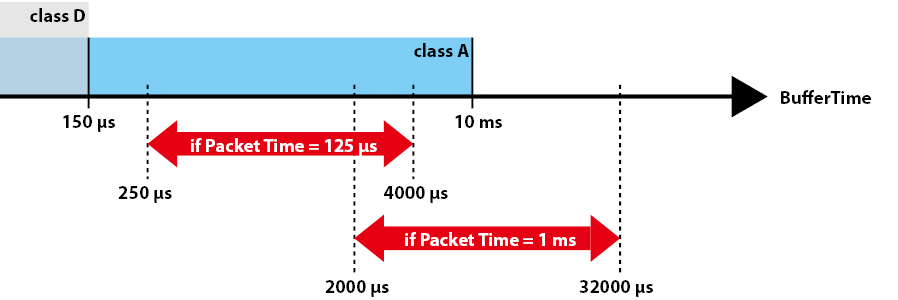
This card is compliant with SMPTE ST 2022-7, and the buffer time when changing transmission routing with PORT 1 and PORT 2 can be adjusted.
The adjustment range is as follows.
250 µs – 4000 µs (when the packet time setting is 125 µs)
2000 µs – 32000 µs (when the packet time setting is 1000 µs)
NOTE
Increasing the buffer time reduces the chance of packet loss when changing transmission routing, but it also increases transmission delay.
Decreasing the buffer time increases the chance of packet loss when changing transmission routing, but it also reduces transmission delay.
Problems with Ethernet connection
Check the IP address, subnet mask and gateway settings.
Confirm that the card is not on a different subnet.
Confirm that the cables have not been selected incorrectly or connected wrong and that they do not have contact failures or broken wiring. (see “Connecting the card”.)
Check the subnet and VLAN settings of the network being used.
Try restarting the card.
Try restarting the device that the card is installed in.
Try again after initializing settings. (see “Reset to Factory Defaults button”.)
If the WebUI Cannot be accessed, try connecting the computer and the CONTROL port directly rather than through a network switch.
PTP synchronization is not possible
Check the PTP settings, including the profile, domain, priority values and various interval values. (see “Sync Screen”.)
Check the Follower Only setting. (see “Sync Screen”.)
Check the SMPTE ST 2022-7 function of the card and the number of cables connected to the card. (see “5. Seamless Protection Switching”.)
Confirm that PTP synchronization is occurring with the correct grandmaster device.
Check the items in “Problems with Ethernet connection” above.
Audio cannot be sent or received
Check the sampling frequency and packet time of this card. (see “Audio Configuration page”.)
Check, for example, the SAP Mode, Ravenna Adv. Mode and NMOS settings of this card. (see “Connection Configuration page”.)
Check the multicast address, UDP port, codec and channels of the stream.
Check the number of channels per stream. ( “Maximum codec and channel numbers”, “Maximum number of streams for this card”)
Confirm that the Startup Config indicator has become green. (see “E Status indicators”.)
Confirm that PTP synchronization is occurring. (See “PTP synchronization is not possible” above.)
Confirm that the clock master setting of the device that this card is installed in is set to IF-ST2110 (this card).
Confirm that the number of cards in the device that this is installed in do not exceed its capacity. (see “Compatible models for installation”.)
Confirm that the cables have not been selected incorrectly or connected wrong and that they do not have contact failures or broken wiring.
Cannot change the buffer time
Confirm that the buffer time is within the adjustment range. (see “Buffer time adjustment range”.)
Confirm that the Startup Config indicator has become green. (see “E Status indicators”.)
Confirm that PTP synchronization is occurring. (See “PTP synchronization is not possible” above.)
0825. MA-3917B