|
|
D01417320H |


Multitrack Recording Console
REFERENCE MANUAL
V2.2
|
|
|
|
|
D01417320H |
Multitrack Recording Console
REFERENCE MANUAL
V2.2
|
|
|
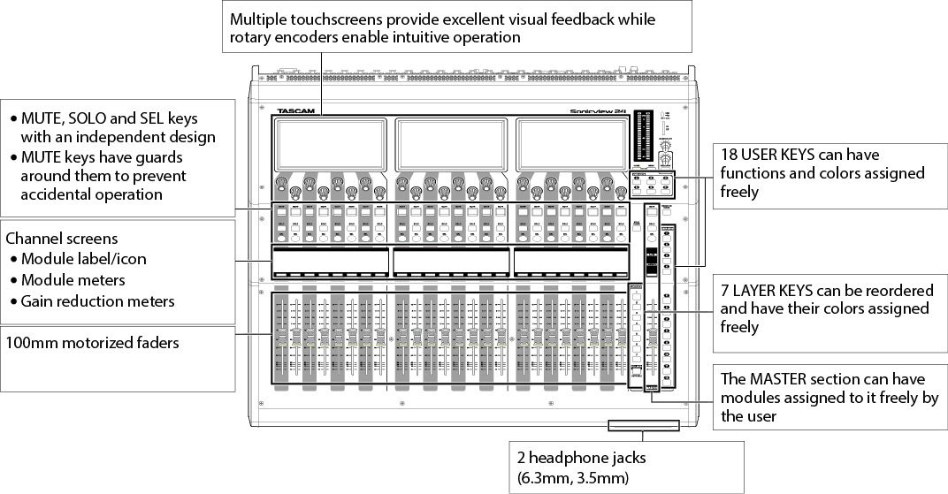
The Sonicview 16XP has 2 touchscreens and 16 channels of mic preamps while the Sonicview 24XP has 3 touchscreens and 24 mic preamps. Both recording mixer models, which are capable of recording and playing up to 32 tracks simultaneously, have 44 internal input channel capability and 24 buses along with Dante and USB audio interface functions.
Main features
 Two 7-inch touchscreens (Sonicview 16XP)
Three 7-inch touchscreens (Sonicview 24XP)
96kHz 54-bit float FPGA hardware mixing engine
Super low latency: 20.8μsec/2-sample mixing engine latency, 0.51ms analog to analog latency
96kHz/32-bit ADC HDIA mic preamps
44 input channels/22 flexible buses and a MAIN L/R bus (all with 31-band GEQ)/4 loop-type FX buses
16 XLR mic/line inputs (+32dBu maximum input) (Sonicview 16XP)
24 XLR mic/line inputs (+32dBu maximum input) (Sonicview 24XP)
16 XLR line outputs
Built-in 64-in/64-out Dante interface (supports redundancy)
Built-in 32-track SDXC recorder
2 TASCAM expansion slots
 SDXC multi-track recording card preinstalled in one slot
Optional MADI, Dante, AES/EBU, and analog outputs cards (sold separately) available for the second slot
32-bit, 32-in/32-out USB audio interface
8 TRS line inputs (channels 9–16 on Sonicview 16XP and channels 17–24 on Sonicview 24XP)
2 inserts (channels 7–8 on Sonicview 16XP and channels 15–16 on Sonicview 24XP)
2 RCA stereo input (ST IN) pairs
XLR talkback input
Separate and external talkback functions
XLR monitor output
2 headphone outputs: 6.3mm (1/4") and 3.5mm (1/8")
2 monitoring sections
Location settings useful for solo DJs
16+1 100mm motorized faders (Sonicview 16XP)
24+1 100mm motorized faders (Sonicview 24XP)
Remote control and off-line editing possible using the dedicated TASCAM Sonicview Control app (macOS, Windows and iPadOS)
High stability with completely separated mixing engine and control surfaces in both hardware and OS
Libraries: Snapshot, Module, Effect, EQ, GEQ, Gate, Comp
18 assignable USER KEYS, 7 custom layers, module-assignable MASTER section and 8 DCAs
16/24 rotary encoders with color LEDs
16/24 channel name LCDs with color LEDs (these also support display of input level meters and gain reduction meters)
Stereo recording (SD cards) and stereo playback (SD cards and USB flash drives)
Word in/out/thru
1000BASE-T Gigabit Ethernet
8-in/8-out GPIO
TS footswitch
XLR-4-31 lamp jack
Power switch with guard
Conventions used in this manual
In this manual, we use the following conventions:
This unit has two types of buttons that can be operated: physical buttons on the top panel and buttons that appear on the touchscreen. The buttons on the top panel are identified as keys, for example, the “MUTE key”.
The sets of 8 knobs beneath the touchscreens are called “LCD knobs” and are identified from left to right as LCD knob 1 – LCD knob 8.
SDHC/SDXC memory cards are referred to as “SD cards”.
“USB flash drives” are sometimes called “USB drives”.
The following modules that handle stereo signals are called “stereo modules”.
CH 1–40 modules when the stereo link setting is on
MIX 1–22 modules when the stereo link setting is on
ST IN 1–2 module
FX RTN 1–4 module
MAIN L/R Master module
The last snapshot that was stored or recalled is called the “current snapshot”.
Additional information is introduced in the styles below when needed:
TIP
These are tips about how to use the unit.
NOTE
These provide additional explanations and describe special cases.
ATTENTION
Failure to follow these instructions could result in damage to equipment or lost data, for example.
 CAUTION
Failure to follow these instructions could result in injury.
TASCAM is a registered trademark of TEAC Corporation.
SDXC Logo is a trademark of SD-3C, LLC.
![]()
VST is a trademark of Steinberg Media Technologies GmbH, registered in Europe and other countries.
![]()
Microsoft, Windows and Windows Media are either registered trademarks or trademarks of Microsoft Corporation in the United States and/or other countries.
Apple, Mac, macOS, iPad, iPadOS and iTunes are trademarks of Apple Inc. in the United States and other countries.
etherCON is a registered trademark of Neutrik AG.
Audinate®, the Audinate logo and Dante are trademarks of Audinate Pty Ltd.
www.audinate.com/patents
ASIO is a trademark of Steinberg Media Technologies GmbH.
![]()
Other company names, product names and logos in this document are the trademarks or registered trademarks of their respective owners.
|
Information is given about products in this manual only for the purpose of example and does not indicate any guarantees against infringements of third-party intellectual property rights and other rights related to them. TEAC Corporation will bear no responsibility for infringements on third-party intellectual property rights or other liabilities that occur as a result of the use of this product. |
|
Properties copyrighted by third parties cannot be used for any purpose other than personal enjoyment and the like without the permission of the right holders recognized by copyright law. Always use this equipment properly. TEAC Corporation will bear no responsibility for rights infringements committed by users of this product. |
This unit uses SD cards for recording and playback.
This unit can use SD cards that are Class 10 or higher and compatible with SDHC or SDXC standards.
Use a USB flash drive to play files on it, as well as to load data to the unit and back up data from it.
Lists of SD cards and USB flash drives that have been confirmed for use with this unit can be found on the TASCAM website.
Sonicview 16XP
https://tascam.jp/int/product/sonicview_16xp/docs
Sonicview 24XP
https://tascam.jp/int/product/sonicview_24xp/docs
Please use SD cards and USB flash drives included in these lists. You can also contact TASCAM customer support.
SD cards and USB flash drives are delicate media.
In order to avoid damaging SD cards and USB flash drives, please take the following precautions when handling them.
Do not leave them in extremely hot or cold places.
Do not leave them in extremely humid places.
Do not let them get wet.
Do not put things on top of them or twist them.
Do not hit them.
Do not remove or insert them during recording, playback, data transmission or other access.
When transporting them, put them into cases, for example.
This unit writes settings data for recording/playback folders on media. Since setting information cannot be written to write-protected SD cards, settings for recording/playback folders will not be retained when the unit is restarted and performance will be otherwise affected.
Always use this unit to format the SD cards and USB flash drives to be used with it. (See “Media Manage Screen”.)
Operation of this unit might be affected when using an SD card or USB flash drive that has been formatted by a computer or other device.
ATTENTION
Formatting erases all the data on the SD card or USB flash drive.
SD cards formatted by this unit are optimized to improve performance during recording. Use this unit to format the SD cards to be used with it. Errors might occur when recording with this unit using an SD card formatted by a computer or other device.
Each 8-channel module has a touchscreen with 8 LCD knobs, enabling intuitive operation of various parameters for each channel allowing simultaneous monitoring and status.
Simultaneous processing capabilities
Input: 40 mono channels and 2 stereo channels
Output buses: 22 switchable AUX/GROUP buses and a stereo main bus
4 internal effects, 4 effect send buses, and 4 stereo effect return channels
Input and output ports
16 or 24 mic/line inputs
2 stereo RCA inputs
16 analog line outputs
Stereo analog monitor outputs
Dante I/O that supports redundancy
2 expansion slots
32-in/32-out USB audio interface port
Internal processing
96kHz/54-bit floating-point arithmetic
Multitrack recording capabilities
32 track (48kHz),16 track (96kHz) Recording/Playback
32 track (48kHz), 16 track (96kHz) Punch IN/OUT
Up to 96kHz
Up to 512 GB SDXC (UHS-I)
This section explains the displays and controls on the top panel.
NOTE
The various buttons that have indicators remain dimly lit even when off, making them easier to see and use even in dark situations.
Channel section
.jpg)
Master section
.jpg)
 Touchscreen
Resistive-type (pressure-sensitive) 800×480 LCD color touchscreen.
Shows a variety of information.
Tap and swipe the screens being shown to operate them.
Only one point on one screen can be operated at a time.
Set the brightness on the PREFERENCES Screen. (See “PREFERENCES screen”.)
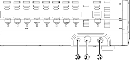
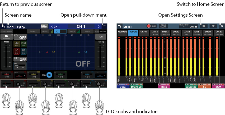
 LCD knobs and indicators
When LCD knobs can be used to control items shown on the touchscreen, their indicators light.
Turn those LCD knobs to adjust various parameters shown on the touchscreen.
NOTE
Parameter adjustment with LCD knobs
Turning an LCD knob without pressing it will change the parameter value by one step with each click. This enables precise parameter adjustment.
When adjusting a parameter with high resolution, turning an LCD knob while pressing it will change the parameter value by multiple steps with each click. This enables efficient parameter adjustment.
By turning any LCD knob while pressing the HOME key, the brightness of the touchscreens, channel screens, various indicators and the lamp connected to the LAMP connector on the rear panel can all be adjusted at the same time.
By pressing and turning any LCD knob while pressing the HOME key, the brightness of the touchscreens and channel screens can be adjusted at the same time.
By turning an LCD knob while pressing the MENU key, the contrast of the channel screen that corresponds to that knob can be adjusted. (See “16 - List of shortcut operations”.)
 MUTE keys and indicators
These mute/unmute modules assigned to the selected layer.
When a MUTE key is on (lit), the signal of the corresponding module is muted.
Depending on the DCA or Mute Group, the key will blink when muted.
When the SENDS ON FADER key is on (Sends On Fader mode is on), these turn sends on/off to the selected bus from the modules assigned to the selected layer (send off when MUTE key lit, send on when MUTE key unlit). For modules that do not have a send on/off function for the subject bus, however, these mute/unmute the corresponding module. (For example, this applies when the subject bus is FX 1 and the module is FX RTN 1 or the subject bus is MIX 1 and the module is MIX 1.)
 SOLO keys and indicators
These turn soloing on/off for modules assigned to the selected layer.
When these keys are on (lit), the signals of the corresponding modules will be sent to the SOLO L/R bus.
The keys will blink if soloing is on because of DCA.
NOTE
Press this key while pressing the MENU key to open the SOLO/OSCILLATOR page, which is where various solo settings can be made, of the TALKBACK / MONITOR / SOLO / OSC SETUP screen. (See “Making solo and built-in oscillator settings” and “16 - List of shortcut operations”.)
 SEL keys and indicators
Press these keys to open the MODULE Screens for modules assigned to the selected layer. The corresponding keys light. If the MODULE Screen shown for a module has been changed on the touchscreen, the corresponding SEL key will light.
When a lit SEL key is pressed, the MODULE screen for that module will be shown on the touchscreen that corresponds to that SEL key if it is not already shown. If the MODULE screen for that module is shown on the touchscreen that corresponds to that SEL key, it will close and the SEL key will become unlit.
NOTE
Pressing one of these keys while pressing the HOME key will set the fader level for the corresponding module to 0 dB. (When Sends On Fader mode is on, the SEND level will be set instead.) (See “16 - List of shortcut operations”.)
These show the following information for modules assigned to the selected layer.
.jpg)
 Sub MODULE LABEL
This shows the module label according to the display mode set for the Sub MODULE LABEL on the DISPLAY MODE page. (See “DISPLAY MODE page”.)
By default, the FIXED MODULE LABEL will be shown.
 Main MODULE LABEL
This shows the module label according to the display mode set for the Main MODULE LABEL on the DISPLAY MODE page. (See “DISPLAY MODE page”.)
By default, the USER MODULE LABEL will be shown.
NOTE
The following three display modes are available for the Main MODULE LABEL and Sub MODULE LABEL.
|
Display mode |
Explanation |
|
USER MODULE LABEL |
Module names set by user |
|
FIXED MODULE LABEL |
Predetermined names for each module (for example, “CH 1” and “MIX 1”) |
|
PORT LABEL |
Names of input and output ports |
The USER MODULE LABEL can be set on the MODULE LABEL Screen. (See “Setting and editing user module labels”.)
 GATE/EXPANDER/DE-ESSER gain reduction meter
 COMP/DUCKER gain reduction meter
 Module icon
See “MODULE LABEL screen” for details about setting module icons.
 Fader level value
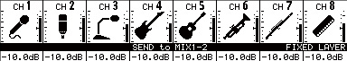
 Module meter (shows signal level of set metering point)
If the module is stereo, a stereo module meter will be shown.
Each module meter has an overload indicator at its top. They will light when the signal level reaches or exceeds −0.00026 dBFS (16-bit full-scale value).
The area below −60 dBFS at the bottom of the module meters will light when above −70 dBFS.
When the SENDS ON FADER key is on (Sends On Fader mode is on), the black and white display is inverted and “SEND to [bus name]” will be shown on a black band at the bottom of the screen.
When the FIX LAYER key ( ) has been used to lock 8 channels to the layer, “FIXED LAYER” will be shown on a white band at the top of the screen.
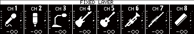
When the Sends On Fader mode is on and 8 channels have been locked to the layer, the black and white display will be inverted and “SEND to [bus name]” and FIXED LAYER” will be shown on a black band at the bottom of the screen.
Use the PREFERENCES Screen to set the brightness and contrast of the channel screens. (See “PREFERENCES screen”.)
 Channel color bars
These show the colors set for the modules assigned to the selected layer. (See “Changing set module colors”.)
 Channel faders
When the SENDS ON FADER key is off (Sends On Fader mode is off), these adjust the fader levels for the modules assigned to the selected layer.
When the SENDS ON FADER key is on (Sends On Fader mode is on), these adjust the send levels to the selected bus for the modules assigned to the selected layer.
 Output meters
These are output meters for the MAIN L/R bus.
The OVER indicators light red when they reach or exceed −0.00026 dBFS (16-bit full-scale value).
The bottommost indicator lights when above −70 dBFS.
 HOME key
When the Menu Screen or a settings screen is open, press to return to the Home Screen on all touchscreens.
Press and hold this key and the MENU key together for 5 seconds to open the LOCK SETUP screen. (See “LOCK SETUP screen”.)
NOTE
Various shortcut operations are possible using this key in combination with others. See “16 - List of shortcut operations” for details.
 MENU key
Press this key to open the Menu Screen on the right touchscreen.
Press and hold this key and the HOME key together for 5 seconds to open the LOCK SETUP screen. (See “LOCK SETUP screen”.)
NOTE
Various shortcut operations are possible using this key in combination with others. See “16 - List of shortcut operations” for details.
 USER KEYS A–F and indicators
Users can assign functions and colors to these keys as they like. When functions that have different statuses are assigned to these keys, they will light, blink and become unlit accordingly. (See “USER DEFINED CONTROLS screen”.)
NOTE
Press one of these keys while pressing the MENU key to open the screen that corresponds to its assigned function. (See “16 - List of shortcut operations”.)
 MUTE key and indicator (MASTER)
This mute/unmutes.
When the SENDS ON FADER is off (Sends On Fader mode is off), this mutes the module assigned to the MASTER slot on the Custom Layer SETUP page of the Layer Key SETUP Screen (MAIN L/R by default).
When the SENDS ON FADER key is on (Sends On Fader mode is on), this mutes the selected bus master module.
When a MUTE key is on (lit), the signal of the corresponding module is muted.
Depending on the DCA or Mute Group, the key will blink when muted.
 SOLO CLEAR key and indicator
The SOLO CLEAR indicator lights when any module is being soloed.
Press this when the SOLO CLEAR indicator is lit to end soloing of all channels.
NOTE
Press this key while pressing the MENU key to open the SOLO/OSCILLATOR page of the TALKBACK / MONITOR / SOLO / OSC SETUP screen. (See “Making solo and built-in oscillator settings” and “16 - List of shortcut operations”.)
 SOLO key and indicator (MASTER)
This turns soloing on and off.
When the SENDS ON FADER is off (Sends On Fader mode is off), this solos the module assigned to the MASTER slot on the Custom Layer SETUP page of the Layer Key SETUP Screen (MAIN L/R by default).
When the SENDS ON FADER key is on (Sends On Fader mode is on), this solos the selected bus master module.
When this key is on (lit), the signal of the corresponding module is sent to the SOLO L/R bus.
The key will blink if soloing is on because of DCA.
NOTE
Press this key while pressing the MENU key to open the SOLO/OSCILLATOR page, which is where various solo settings can be made, of the TALKBACK / MONITOR / SOLO / OSC SETUP screen. (See “Making solo and built-in oscillator settings” and “16 - List of shortcut operations”.)
 SEL key and indicator (MASTER)
When the SENDS ON FADER is off (Sends On Fader mode is off), this functions as the SEL key for the module assigned to the MASTER slot on the Custom Layer SETUP page of the Layer Key SETUP Screen (MAIN L/R by default).
When the SENDS ON FADER key is on (Sends On Fader mode is on), this functions as the SEL key for the selected bus master module.
Press this key, lighting it, to open the MODULE screen for the assigned module on the right touchscreen. If the MODULE Screen shown for a module has been changed on the touchscreen, the corresponding SEL key will light.
When a lit SEL key is pressed, the MODULE screen for the that module will be shown on the touchscreen that corresponds to that SEL key if it is not already shown. If the MODULE screen for that module is shown on the touchscreen that corresponds to that SEL key, it will close and the SEL key will become unlit.
NOTE
Pressing this key while pressing the HOME key will set the fader/send level for the corresponding module to 0 dB. (See “16 - List of shortcut operations”.)
 L/R indicator
When the SENDS ON FADER key is off (Sends On Fader mode is off) and MAIN L/R is the module assigned to the MASTER slot on the Custom Layer SETUP page of the Layer Key SETUP Screen, the MUTE, SOLO and SEL keys, the color bar and the MASTER fader in the top panel master section will control/display the MAIN L/R Master module, and the indicator will light.
This indicator will be unlit when the SENDS ON FADER key is on (Sends On Fader mode is on), as well as when the SENDS ON FADER key is off and MAIN L/R is not the module assigned to the MASTER slot on the Custom Layer SETUP page of the Layer Key SETUP Screen.
 SEND indicator
This indicator will be unlit when the SENDS ON FADER key is off (Sends On Fader mode is off).
When the SENDS ON FADER key is on (Sends On Fader mode is on), the MUTE, SOLO and SEL keys, the color bar and the MASTER fader in the top panel master section will control/display the SENDS ON FADER operation bus (MIX 1–22/FX 1–4) and the indicator will light.
 Color bar (MASTER)
When the SENDS ON FADER is off (Sends On Fader mode is off), this lights with this color set for the module assigned to the MASTER slot on the Custom Layer SETUP page of the Layer Key SETUP Screen (MAIN L/R by default). (See “Changing set module colors”.)
When the SENDS ON FADER key is on (Sends On Fader mode is on), this lights with the color set for the selected bus master module. (See “Changing set module colors”.)
 LAYER KEYS 1–7 and indicators
Press these keys to switch layers. The last pressed key will light, showing the current selection. Switching layers will change the states of module faders, MUTE/SOLO/SEL keys, channel screens, color bars and touchscreens to correspond to the current layer.
The layer assignments of keys and their colors can be set freely by opening Menu Screen > Front Panel Setup menu > Layer/Master Fader Setup. (See “Layer Key SETUP page”.)
NOTE
The Layer Key SETUP screen for the selected LAYER key can be opened by pressing that key while pressing the MENU key. (See “Layer Key SETUP page” and “16 - List of shortcut operations”.)
 MASTER fader
When the SENDS ON FADER key is off (Sends On Fader mode is off), this adjusts the fader level of the module assigned to the MASTER slot on the Custom Layer SETUP page of the Layer Key SETUP Screen (MAIN L/R by default).
When the SENDS ON FADER key is on (Sends On Fader mode is on), this adjusts the fader level of the selected bus master module.
FIX LAYER key and indicator
While pressing this key, press a SEL key for a block to fix the corresponding block of 8 channels to the current layer. This key and the LAYER KEYS that corresponds to the fixed layer will blink. “FIXED LAYER” will be shown on a white band at the top of the corresponding channel screen.
While pressing this key, press a SEL key for a block with a fixed layer to cancel fixing the corresponding block of 8 channels to a layer. This key and the LAYER KEYS that corresponds to the layer that is no longer fixed will stop blinking. “FIXED LAYER” will stop being shown at the top of the corresponding channel screen.
Either the left or right block of 8 channels can be fixed at a time.
 USB port (5V
 0.5A)
0.5A)
This is a USB Type-C port. (This supports USB 2.0.)
Connect a USB keyboard here, and use it to enter names, for example. By default, the unit is set to use a Japanese keyboard. Since English and Japanese keyboards use different layouts, change the setting on the PREFERENCES screen if using an English keyboard. (See “PREFERENCES screen”.)
Load a USB flash drive to play files on it, as well as to load data into and back up data from this unit.
Mice and other pointing devices are not supported.
 SD card slot
SD cards can be inserted into this slot. (See “Connecting and disconnecting SD cards and USB flash drives”.)
Load an SD card to play files on it and record to it, as well as to load data into and back up data from this unit.
 MONITOR OUT volume
Use this to adjust the output level of the MAIN OUTPUT L/R jacks.
Use this to adjust the TALKBACK input level.
This key turns talkback on and off. Press this key briefly to switch it on/off. Press this key continuously to turn the function on only while being pressed.
Press this key while pressing the MENU key to open the TALKBACK page, which is where various talkback settings can be made, of the TALKBACK / MONITOR / SOLO / OSC SETUP screen. (See “Making talkback settings” and “16 - List of shortcut operations”.)
 SENDS ON FADER key and indicator
This turns the Sends On Fader mode on/off.
When the SENDS ON FADER key is on (Sends On Fader mode is on), this key lights and the unit operates as follows.
The SENDS ON FADER screen opens on the rightmost touchscreen. (See “SENDS ON FADER function”.)
This changes the Channel Screens to Sends On Fader mode display.
The channel faders move to the SEND level positions of the selected buses.
The MASTER fader moves to the FADER level position of the selected bus.
Press this key when the SENDS ON FADER screen is shown to end Sends On Fader mode. This will close the SENDS ON FADER screen and return the channel faders, MASTER fader and channel screens to their normal display states. (See “SENDS ON FADER function”.)
 USER KEYS 1–12 and indicators
Users can assign functions and colors to these keys as they like. When functions that have different statuses are assigned to these keys, they will light, blink and become unlit accordingly. (See “USER DEFINED CONTROLS screen”.)
Press one of these keys while pressing the MENU key to open the screen that corresponds to its assigned function. (See “16 - List of shortcut operations”.)
 Headphone jack (stereo mini)
Use this 3.5mm (1/8") stereo mini jack to connect stereo headphones.
 Headphone jack (stereo phone)
Use this 6.3mm (1/4") stereo phone jack to connect stereo headphones.
 Headphone volume
Use this to adjust the headphone output level.
CAUTION
Before connecting headphones, minimize the volume with the headphone knob. Failure to do so might cause sudden loud noises, which could harm your hearing or result in other trouble.
Sonicview 16XP
.jpg)
Sonicview 24XP
.jpg)
 LAMP jack
Use this to connect a gooseneck lamp to the illuminate the top of the unit.
Lamps with 4-pin XLR connectors can be used.
Adjust the lamp brightness on the PREFERENCES Screen. (See “PREFERENCES screen”.)
XLR 4-pin female (pin 4: +12V, pin 3: GND)
 MIC/LINE input jacks
These are balanced XLR jacks for mic/line input.
XLR (1: GND, 2: HOT, 3: COLD)
 LINE IN (BAL) jacks (TRS phone)
These are 6.3mm (1/4") TRS phone jacks for line input.
TRS (Tip: HOT, Ring: COLD, Sleeve: GND)
NOTE
This unit has some channels with two types of input jacks (XLR and TRS). Do not input signals through both the XLR and TRS jacks of the same channel at the same time. If signals are input at the same time, they will not be input properly.
Only MIC/LINE input jacks () provide phantom power.
 INSERT jacks (TRS phone)
Use these 6.3mm (1/4") TRS phone jacks to connect external devices (including effects).
TRS (Tip: SEND, Ring: RETURN, Sleeve: GND)
 TALKBACK input jack
Connect a talkback mic here.
Use the TALKBACK volume knob ( ) to adjust the talkback input level, and use the TALKBACK key (
 ) to turn it on/off.
Make talkback settings on the TALKBACK page of the TALKBACK / MONITOR / SOLO / OSC SETUP screen. (See “Making talkback settings”.)
 Analog output jacks
These analog outputs are XLR jacks.
XLR (1: GND, 2: HOT, 3: COLD)
 Dante PRIMARY connector
This is the main etherCON Cat5e-compatible Dante transmission connector.
Use this to connect to a Dante network all the time. For LAN cables used for connection, use STP cables that are category 5e or higher. (See “Connecting to a Dante network”.)
Make settings for the built-in Dante module on the Dante SETUP Screen. (See “Dante SETUP screen”.)
 Dante SECONDARY connector
This is the secondary etherCON Cat5e-compatible Dante transmission connector. The use changes depending on the mode.
When in redundant mode, this connects to the secondary Dante network.
When in switched (daisy-chain) mode, use this to connect another Dante device in the chain. For LAN cables used for connection, use STP cables that are category 5e or higher. (See “Connecting to a Dante network”.)
Make settings for the built-in Dante module on the Dante SETUP Screen. (See “Dante SETUP screen”.)
 Expansion card slots (SLOT 2)
These slots can be used to install expansion cards (sold separately).
Make SLOT settings on the SLOT SETUP Screen. (See “SLOT SETUP screen”.)
 WORD THRU/OUT connector
This BNC connector is for word clock output.
Use it for thru and normal output of word clock signals.
Switch word thru/output on the SYNC CLOCK Screen. (See “SYNC CLOCK screen”.)
 WORD IN connector
This BNC connector is for word clock input.
Use it for word clock signal input.
Connect a word clock signal to this connector when synchronizing the word clock of this unit and other equipment.
 FOOTSWITCH jack
This 6.3mm (1/4") TS phone jack is for connecting a footswitch.
Set functions assigned to the footswitch on the USER DEFINED CONTROL Screen Foot Switch page. (See “Foot Switch page”.)
TS (Tip: HOT, Sleeve: GND)
 USB to PC port
This is a USB Type-B port.
Use a USB cable (Type-A to Type-B) to connect the unit to a computer.
ATTENTION
The unit should be connected directly to the computer, not through a USB hub. Moreover, proper transmission with a computer could fail if the cable is too long.
 ETHERNET port
This is an Ethernet port.
Use this to connect to a network, primarily for the purpose of remote control of this unit using the dedicated TASCAM Sonicview Control application.
Make network settings on the Network Setup Screen. (See “Network Setup screen”.)
For details about the TASCAM Sonicview Control application, see its manual. TASCAM Sonicview Control and its application manual can be downloaded from the TASCAM website.
Sonicview 16XP
https://tascam.com/us/product/sonicview_16xp/support
Sonicview 24XP
https://tascam.com/us/product/sonicview_24xp/support
 SD card slot for MTR
This slot is for SD cards used with the MTR.
Load an SD card to play files on it and record to it, as well as to back up MTR data.
NOTE
IF-MTR32 recording card in integrated into the Sonicview 16XP and Sonicview 24XP (US version only)
 GPIO connector
This is a 25-pin D-sub Parallel control input/output connector.
It can send and receive control commands with 8 inputs and 8 outputs. See “GPIO connector overview” for details about pin assignments.
Set functions assigned to the GPIO input connector on the USER DEFINED CONTROL Screen GPIO-IN page. (See “GPIO-IN page”.)
Set functions assigned to the GPIO output connector on the USER DEFINED CONTROL Screen GPIO-OUT page. (See “GPIO-OUT page”.)
 MONITOR OUT L/R jacks
These analog outputs are XLR jacks.
Make monitor output settings on the MONITOR 1/2 pages of the TALKBACK / MONITOR / SOLO / OSC SETUP screen.(See “Making monitor output settings”.)
XLR (1: GND, 2: HOT, 3: COLD)
 ST IN 1/ST IN 2 jacks
These RCA pin jacks are analog line outputs.
Use RCA cables to connect CD players and similar devices to these jacks.
 POWER switch
This turns the power on/off.
CAUTION
Before turning the power on or off, minimize the volumes of connected equipment. Failure to do so might cause sudden loud noises, which could harm your hearing or result in other trouble.
NOTE
Do not interrupt the power when the unit is operating (including recording, playing back, or writing data to an SD card or USB flash drive). Doing so could cause proper recording to fail and recorded data to be lost.
We recommend executing the Save Current Settings command on the Menu Screen before turning the unit off. (See “Saving the current settings”.)
 AC IN connector
Plug the included power cord in here.
The GPIO connector on the back of the unit is a parallel control connector that allows this unit to control and be controlled by other devices.
GPIO connector function settings can be changed on the USER DEFINED CONTROLS Screen GPIO-IN and GPIO-OUT pages. (See “USER DEFINED CONTROLS screen”.)
The pin assignments are as follows.
|
Pin No. |
Function |
IN/OUT |
|
1 |
GND |
- |
|
2 |
GPIO IN 2 |
IN |
|
3 |
GPIO IN 4 |
IN |
|
4 |
GPIO IN 6 |
IN |
|
5 |
GPIO IN 8 |
IN |
|
6 |
NC |
- |
|
7 |
NC |
- |
|
8 |
NC |
- |
|
9 |
GPIO OUT 2 |
OUT |
|
10 |
GPIO OUT 4 |
OUT |
|
11 |
GPIO OUT 6 |
OUT |
|
12 |
GPIO OUT 8 |
OUT |
|
13 |
NC |
- |
|
14 |
GPIO IN 1 |
IN |
|
15 |
GPIO IN 3 |
IN |
|
16 |
GPIO IN 5 |
IN |
|
17 |
GPIO IN 7 |
IN |
|
18 |
NC |
- |
|
19 |
NC |
- |
|
20 |
GND |
- |
|
21 |
GPIO OUT 1 |
OUT |
|
22 |
GPIO OUT 3 |
OUT |
|
23 |
GPIO OUT 5 |
OUT |
|
24 |
GPIO OUT 7 |
OUT |
|
25 |
+5V |
- |
IN: For command input
Internal circuit with +5V pull-up
Operates with low signal input of 50 msec or longer
OUT: For command and tally output
Internal circuit is open collector (10Ω output impedance)
20V dielectric strength, 35mA maximum current
+5V: 50mA maximum supplied current
Touchscreen operations
Tap/swipe items on the touchscreens to operate them.
Special touchscreen operations
|
Press and hold |
Press and hold the +48V button to turn phantom power (+48V) on and off. |
|
Tap / press and hold |
Tapping the DIM button on the MONITOR 1/2 page of the TALKBACK / MONITOR / SOLO / OSC SETUP screen, or tapping the TALKBACK, TARGET or SELECTED button on the TALKBACK page will turn that function on/off. Pressing and holding one will turn that function on temporarily until released. |
LCD knob operations
The LCD knobs can be used to control the parameters shown and selected above them on the touchscreen.
When LCD knobs can be used, the corresponding indicators light.
|
LCD knob |
Explanation |
|
Turn without pressing |
This allows precise adjustment of one step per click. |
|
Turn while pressing |
This allows quick parameter adjustment from one extreme to the other. |
Top panel key operations
Press keys on the top panel to use them.
The following keys have special operation procedures.
|
Key |
Use |
|
TALKBACK key |
Press this key briefly to turn talkback on/off. Press this key continuously to turn the function on only while being pressed. |
|
HOME key + MENU key |
Press and hold the HOME and MENU keys together for 5 seconds to open the LOCK SETUP Screen. |
NOTE
The parameters of this unit have unified image colors, making identification of parameter types easy by color.
GAIN/Level: Red
GATE: Yellow-green
EQ: Blue
COMP: Green
FX: Yellow-green
AUX mode bus: Orange
GROUP mode bus: Purple
PAN: Yellow
FADER: Light blue
This unit has multiple Home Screens for its layers. The names of modules assigned to layers, various parameters, meters and other items are shown in lists.
Press LAYER KEYS 1–7 to change what is shown on the Home Screen.
NOTE
When the Menu Screen or a settings screen is open, press the HOME key to return to the Home Screen.
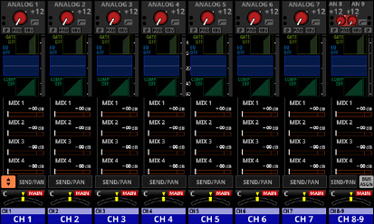
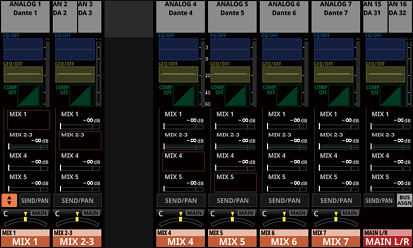
CH 1–40 Module Home Screen
.jpg)
CH 1–40 Module Home Screen details
INPUT area
This shows the input settings of the selected input source. (A stereo module is shown on the right.)
.jpg)
Input area when the input source is “ANALOG” or “SB-16D connected by built-in Dante” and the PORT LABEL display mode is “FIXED”, or the PORT LABEL display mode is “USER” and the USER PORT LABEL is undefined
.jpg)
Input area when the input source is not “ANALOG” or “SB-16D connected by built-in Dante” and the PORT LABEL display mode is “FIXED”, or the PORT LABEL display mode is “USER” and the USER PORT LABEL is undefined
This shows the input source name.
If the PORT LABEL display mode is “USER”, the USER PORT LABEL (the port name set by the user) will be shown. If the USER PORT LABEL is undefined, the FIXED PORT LABEL will be shown. (See “DISPLAY MODE page”.)
If the PORT LABEL display mode is “FIXED”, the FIXED PORT LABEL will be shown for each port (for example, “ANALOG 1” or “Dante 1”). (See “DISPLAY MODE page”.)
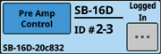
If a Dante port that has a mounted SB-16D assigned is selected, “SB#[ID] [port number]” will be shown.

If it is a virtually-mounted SB-16D, ![]() will appear to the bottom left of the port name.
will appear to the bottom left of the port name.

If the module is stereo and input sources that are not left-right adjacent are selected, the FIXED PORT LABEL for the input sources will appear split left and right and abbreviated as follows.

|
Input source name |
Input source name abbreviation |
|
ANALOG |
AN |
|
Dante |
DA |
|
SLOT 1 |
S1 |
|
USB |
US |
|
ST IN 1 |
ST1 |
|
PLAYER |
PL |
When a module is stereo, if a Dante port that has a mounted SB-16D assigned is selected, “#[ID] [port number]” will be shown.

If it is a virtually-mounted SB-16D, the # background will be yellow.

These indicators appear to light as shown below depending on the input level. When a module is stereo, two sets of module indicators will be shown separately left and right.
Red: −3 dBFS, Green: −40 dBFS
This shows the input signal phase setting status. When a module is stereo, two module phase settings will be shown separately left and right.
|
|
Normal |
|
|
Reversed |
This shows the −20 dB pad setting status when the input source of the selected module is “ANALOG” or “SB-16D connected by built-in Dante”. When on, the icon will appear highlighted.
When the input sources for both the left and right channels of a stereo module are “ANALOG” or “SB-16D connected by built-in Dante”, if settings are different for the left and right channels, the colors on the left and right sides of the buttons will be different.
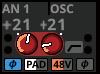
This shows the phantom power (+48V) setting status when the input source of the selected module is “ANALOG” or “SB-16D connected by built-in Dante”. When on, the icon will appear highlighted.
When the input sources for both the left and right channels of a stereo module are “ANALOG” or “SB-16D connected by built-in Dante”, if settings are different for the left and right channels, the colors on the left and right sides of the buttons will be different.
This shows the HPF setting status. When on, the icon will appear highlighted.
When the input source of the selected module is “ANALOG” or “SB-16D connected by built-in Dante”, this will show an analog gain knob and the input level of the unit or SB-16D MIC/LINE input jacks. When a module is stereo, two knobs and input level values will be shown for the module.
A black knob that cannot be operated will be shown if the input source is an SB-16D for which control privileges are not held.

 A D.TRIM knob and the digital trim value will be shown when the input source of the selected module is not “ANALOG” or “SB-16D connected by built-in Dante”. When a module is stereo, two knobs and digital trim values will be shown for the module.
Tap this area to show the selection frame. When the selection frame is shown, corresponding LCD knobs can be used to adjust the parameters shown.
When the selection frame is shown, tap this area to open the MODULE (INPUT) Screen for the selected module. (See “MODULE (INPUT) Screen”.)
GATE/EXPANDER/DE-ESSER area
This shows the response graphs and gain reduction meters of dynamics effects.
Tap this area to open the MODULE (GATE/EXPANDER/DE-ESSER) Screen for the selected module. (See “MODULE (GATE/EXPANDER/DE-ESSER) screens”.)
HPF/EQ area
This shows graphs of the HPF and EQ frequency responses.
Tap this area to open the MODULE (EQ) Screen for the selected module. (See “MODULE (EQ) Screen”.)
COMP/DUCKER area
This shows the response graphs and gain reduction meters of dynamics effects.
Tap this area to open the MODULE (COMP/DUCKER) Screen for the selected module. (See “MODULE (COMP/DUCKER) Screen”.)
INSERT indicator
The ![]() indicator is shown when the INSERT button is on for the CH 1–40 module.
indicator is shown when the INSERT button is on for the CH 1–40 module.
 Level meter
This shows the level of the signal at the set metering point. (See “METERING POINT page” and “MODULE (OVERVIEW) Screen”.)
NOTE
If the selected module is stereo, a stereo level meter will be shown.
Each level meter has an overload indicator at its top. They will appear to light red when the signal level reaches or exceeds −0.00026 dBFS (16-bit full-scale value).
When a level overload occurs, the entire bar meter will light red.
The area below −60 dBFS at the bottom of the level meters will light when above −70 dBFS.
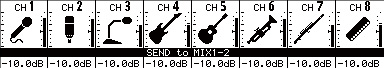
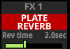
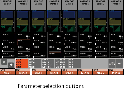
SEND area
This shows the states of SEND settings to MIX 1–22 and FX 1–4 buses 4 at a time. This also shows the parameters of the Audio Follow Video function.
.jpg)
.jpg)
This shows the MODULE LABEL set for the Main MODULE LABEL of the MIX 1–22 or FX RTN 1–4 module. (See “DISPLAY MODE page”.)
If the Main MODULE LABEL display mode is “USER” but the USER MODULE LABEL for that module is undefined, the FIXED MODULE LABEL will be shown (for example, “MIX 1” or “FX 1”).
This shows the PRE/POST setting used for MIX 1–22 and FX 1–4 buses.
|
No indicator |
Set to POST |
|
PRE |
Set to PRE |
These show the assignment state and send level to MIX 1–22 and FX 1–4 buses in AUX mode.
|
MIX 1–22 bus |
Shown in orange |
|
FX 1–4 bus |
Shown in green |
This will be gray when not assigned.
If a MIX or FX bus is stereo-linked, send levels will be shown with two bars.
Purple rounded buttons are shown when GROUP mode MIX 1–22 buses are ON. These appear but cannot be turned on/off on the Home Screen.
Tap a SEND level to show the selection frame. When the selection frame is shown, corresponding LCD knobs can be used to adjust the SEND level shown.
When the selection frame is shown, tap this area to open the MODULE (SEND/PAN) Screen for the selected module. (See “MODULE (SEND/PAN) Screen”.)
Tap the SEND level while pressing the HOME key to set the SEND level for that bus to 0 dB. (See “16 - List of shortcut operations”.)
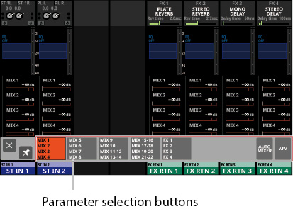
![]() button
button
Tap this button to show the selection window for the parameters shown in the SEND area.
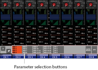
Tap a parameter selection button to open the selected parameter group in the SEND area.
Tap the ![]() button at the top left of the selection window to close it.
button at the top left of the selection window to close it.
When the ![]() button is off (
button is off (![]() ), tapping a parameter selection button will automatically close this window.
), tapping a parameter selection button will automatically close this window.
When the ![]() button is on (
button is on (![]() ), tapping a parameter selection button will not close this window.
), tapping a parameter selection button will not close this window.
Tapping the AFV button will show 4 key parameters of the Audio Follow Video function in the SEND area.
.jpg)
ON/OFF button for the Audio Follow Video function of the selected module
Tap this button to turn on/off the Audio Follow Video function of the selected module. When ON, buttons will be highlighted.
This shows the name of the AFV TRIGGER SOURCE selected on the AFV TRIGGER SOURCE SELECT Screen.
WAIT
This adjusts the amount of time until fading starts after receiving an AFV ON event.
RISE
This adjusts the amount of fade time until the ON LEVEL is reached after fading starts when an AFV ON event is received.
FALL
This adjusts the amount of fade time until the OFF LEVEL is reached after fading starts when an AFV OFF event is received.
Tapping – will make a selection frame appear. When a selection frame is shown, corresponding LCD knobs can be used to adjust the parameters shown.
When a selection frame is shown, tap this area to open the MODULE (Audio Follow Video) Screen for the selected module. (See “MODULE (Audio Follow Video) Screen”.)
Tap the AUTO MIXER button to show the parameters and meters for the AUTO MIXER function in the SEND areas of the CH 1–16 modules. In this case, the send areas will be empty for modules other than the CH 1–16 modules.
.jpg)
AUTO MIXER GROUP button
This shows the name of the AUTO MIXER group (A/B/C/D) to which the corresponding channel module belongs. “---” will be shown if a group that is not subject to the AUTO MIXER is selected.
If the selected group is TOP PRIORITY, a “TOP” icon will be shown in the bottom left of the button. When the TOP PRIORITY setting is ON, this “TOP” icon will appear highlighted.
When the group AUTO MIXER function is OFF, this will appear dimmed.
Tap this button to open the AUTOMATIC MIXER Screen. (See “AUTO MIXER Function”.)
AUTO MIXER GAIN level meter
This shows the gain level as it is automatically adjusted by the AUTO MIXER.
AUTO MIXER GATE indicator
This indicator shows whether or not the gate is closed for the subject channel in the AUTO MIXER.
This lights when the GATE is closed and the input level to the AUTO MIXER is −90 dB or less. When the input level to the AUTO MIXER is −84 dB or higher and the GATE is open, it will be unlit.
AUTO MIXER WEIGHT setting indicator
This shows the current WEIGHT value for the AUTO MIXER.
Tap this area to show the selection frame. When the selection frame is shown, the corresponding LCD knob (lit light blue) can be used to adjust the WEIGHT value shown.
SEND/PAN button
Tap this button to open the MODULE (SEND/PAN) Screen. (See “MODULE (SEND/PAN) Screen”.)
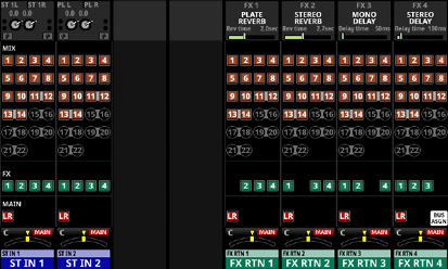
Tap this button to switch from the normal display to the BUS ASSIGN display.
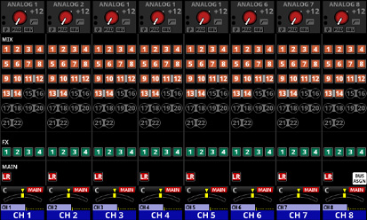
The SEND settings states for the MIX 1–22, FX 1–4 and MAIN L/R buses are shown as follows. (See “MODULE (SEND/PAN) Screen”.)
|
Icon |
SEND ON/OFF |
PRE/POST |
|
|
ON |
POST |
|
|
ON |
PRE |
|
|
OFF |
POST |
|
|
OFF |
PRE |
The BUS mode setting states for the MIX 1–22 modules are shown as follows. (See “BUS CONFIG page”.)
|
Icon |
Meaning |
|
|
MIX 1–22 modules when the BUS mode is AUX |
|
|
MIX 1–22 modules when the BUS mode is GROUP |
|
|
MIX 1–22 modules with Stereo Link setting on |
Tap the ![]() button when BUS ASSIGN display is active to return to normal display.
button when BUS ASSIGN display is active to return to normal display.
PAN area
This shows the pan/balance setting of the signals sent to the MAIN L/R bus as well as the MAIN L/R bus assignment status.
Tap this area to show the selection frame. When the selection frame is shown, corresponding LCD knobs can be used to adjust the pan/balance of the sent signals.
Tap this area while pressing the HOME key to set the tapped pan/balance setting to center (C). (See “16 - List of shortcut operations”.)
When the selection frame is shown, tap this area to open the MODULE (SEND/ PAN) Screen. (See “MODULE (SEND/PAN) Screen”.)
The module label at the left of the top line is shown according to the display mode set for the Sub MODULE LABEL on the DISPLAY MODE page. By default, the FIXED MODULE LABEL will be shown. (See “DISPLAY MODE page”.)
At the top right, the Mute Group assignment status is shown in the top line and the DCA assignment status is shown in the bottom line. Red numbers show the assigned Mute Group numbers. Yellow numbers show the assigned DCA numbers.

See “Mute Group Assign page” and “MODULE (OVERVIEW) Screen” for changing Mute Group assignments.
See “DCA Assign page” and “MODULE (OVERVIEW) Screen” for changing DCA assignments.
The bottom line shows the module label according to the display mode set for the Main MODULE LABEL on the DISPLAY MODE page. By default, the USER MODULE LABEL will be shown. (See “DISPLAY MODE page”.)
The MODULE LABEL area background color is the color set for the assigned module. See “Changing set module colors” to change set module colors.
Tap this area to open the MODULE (OVERVIEW) Screen. (See “MODULE (OVERVIEW) Screen”.)
NOTE
The following three display modes are available for the Main MODULE LABEL and Sub MODULE LABEL.
|
Display mode |
Explanation |
|
USER MODULE LABEL |
Module name set by user |
|
FIXED MODULE LABEL |
Predetermined names for each module (for example, “CH 1” and “MIX 1”) |
|
PORT LABEL |
Names of input and output ports |
The USER MODULE LABEL can be set on the MODULE LABEL Screen. (See “Setting and editing user module labels”.)
ST IN 1–2/FX RTN 1–4 Module Home Screen
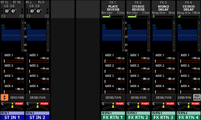
ST IN 1–2/FX RTN 1–4 Module Home Screen
.jpg)
ST IN 1–2/FX RTN 1–4 Module Home Screen details
INPUT area
This shows the input settings of the selected input source.
.jpg)
Input area display when the input source is not “ANALOG” or “SB-16D connected by built-in Dante”
.jpg)
Input area display when the input source is “ANALOG” or “SB-16D connected by built-in Dante”
This shows the input source name.
If the PORT LABEL display mode is “USER”, the USER PORT LABEL (the port name set by the user) will be shown. If the USER PORT LABEL is undefined, the FIXED PORT LABEL will be shown. (See “DISPLAY MODE page”.)
If the PORT LABEL display mode is “FIXED”, the FIXED PORT LABEL will be shown for each port (for example, “ANALOG 1” or “Dante 1”). (See “DISPLAY MODE page”.)
If a Dante port that has a mounted SB-16D assigned is selected, “SB#[ID] [port number]” will be shown.
If it is a virtually-mounted SB-16D, ![]() will appear to the bottom left of the port name.
will appear to the bottom left of the port name.
If the module is stereo and input sources that are not left-right adjacent are selected, the FIXED PORT LABEL for the input sources will appear split left and right and abbreviated as follows.
|
Input source name |
Input source name abbreviation |
|
ANALOG |
AN |
|
Dante |
DA |
|
SLOT 1 |
S1 |
|
USB |
US |
|
ST IN 1 |
ST1 |
|
PLAYER |
PL |
When a module is stereo, if a Dante port that has a mounted SB-16D assigned is selected, “#[ID] [port number]” will be shown.
If it is a virtually-mounted SB-16D, the # background will be yellow.
These indicators appear to light as shown below depending on the input level.
Red: −3 dBFS, Green: −40 dBFS
This shows the input signal phase setting status.
|
|
Normal |
|
|
Reversed |
A D.TRIM knob and the digital trim value will be shown when the input source of the selected module is not “ANALOG” or “SB-16D connected by built-in Dante”.
This shows the −20 dB pad setting status when the input source of the selected module is “ANALOG” or “SB-16D connected by built-in Dante”. When on, the icon will appear highlighted.
If the input sources for both the left and right channels of a stereo module are “ANALOG” or “SB-16D connected by built-in Dante”, this shows the left channel setting.
This shows the phantom power (+48V) setting status when the input source of the selected module is “ANALOG” or “SB-16D connected by built-in Dante”. When on, the icon will appear highlighted.
If the input sources for both the left and right channels of a stereo module are “ANALOG” or “SB-16D connected by built-in Dante”, this shows the left channel setting.
When the input source of the selected module is “ANALOG” or “SB-16D connected by built-in Dante”, this will show 2 analog gain knobs and the input level values of the unit or SB-16D MIC/LINE input jacks.
A black knob that cannot be operated will be shown if the input source is an SB-16D for which control privileges are not held.
Tap this area to show the selection frame. When the selection frame is shown, corresponding LCD knobs can be used to adjust the parameters shown.
When the selection frame is shown, tap this area to open the MODULE (INPUT) Screen for the selected module. (See “MODULE (INPUT) Screen”.)
FX area
This shows effects names and main effect parameters.
Tap this area to show the selection frame. When the selection frame is shown, corresponding LCD knobs can be used to adjust effect parameters shown.
When the selection frame is shown, tap this area to open the MODULE (FX) Screen for the selected module. (See “MODULE (FX) Screen”.)
When the FX SEND MUTE button on the MODULE (FX) Screen is on, the FX RTN 1–4 modules on the Home Screen will also be highlighted red.
EQ area
This shows a graph of the EQ frequency response.
Tap this area to open the MODULE (EQ) Screen for the selected module. (See “MODULE (EQ) Screen”.)
Level meters
This shows the level of the signal at the set metering point. (See “METERING POINT page”, “ST IN 1–2 MODULE (OVERVIEW) Screens” and “FX RTN 1–4 MODULE (OVERVIEW) Screens”.)
NOTE
The ST IN 1–2/FX RTN 1–4 modules are stereo, so stereo level meters are shown.
Each level meter has an overload indicator at its top. They will appear to light red when the signal level reaches or exceeds −0.00026 dBFS (16-bit full-scale value).
When a level overload occurs, the entire bar meter will light red.
The area below −60 dBFS at the bottom of the level meters will light when above −70 dBFS.
This shows the states of SEND settings to MIX 1–22 and FX 1–4 buses 4 at a time. This also shows the parameters of the Audio Follow Video function.
1.jpg)
1.jpg)
This shows the MODULE LABEL set for the Main MODULE LABEL of the MIX 1–22 or FX RTN 1–4 module. (See “DISPLAY MODE page”.)
If the Main MODULE LABEL display mode is “USER” but the USER MODULE LABEL for that module is undefined, the FIXED MODULE LABEL will be shown (for example, “MIX 1” or “FX 1”).
This shows the PRE/POST setting used for MIX 1–22 and FX 1–4 buses.
|
No indicator |
Set to POST |
|
PRE |
Set to PRE |
These show the assignment state and send level to MIX 1–22 and FX 1–4 buses in AUX mode.
|
MIX 1–22 bus |
Shown in orange |
|
FX 1–4 bus |
Shown in green |
This will be gray when not assigned.
If a MIX or FX bus is stereo-linked, send levels will be shown with two bars.
Purple rounded buttons are shown when GROUP mode MIX 1–22 buses are ON. These appear but cannot be turned on/off on the Home Screen.
 , and are not shown in the FX 1–4 area of the FX RTN module.
.jpg)
Tap a SEND level to show the selection frame. When the selection frame is shown, corresponding LCD knobs can be used to adjust the SEND level shown.
Tap the SEND level while pressing the HOME key to set the SEND level for that bus to 0 dB. (See “16 - List of shortcut operations”.)
![]() button
button
Tap this button to show the selection window for the parameters shown in the SEND area.
Tap a parameter selection button to open the selected parameter group in the SEND area.
Tap the ![]() button at the top left of the selection window to close it.
button at the top left of the selection window to close it.
When the ![]() button is off (
button is off (![]() ), tapping a parameter selection button will automatically close this window.
), tapping a parameter selection button will automatically close this window.
When the ![]() button is on (
button is on (![]() ), tapping a parameter selection button will not close this window.
), tapping a parameter selection button will not close this window.
Tapping the AFV button will show 4 key parameters of the Audio Follow Video function in the SEND area.
1.jpg)
ON/OFF button for the Audio Follow Video function of the selected module
Tap this button to turn on/off the Audio Follow Video function of the selected module. When ON, buttons will be highlighted.
This shows the name of the AFV TRIGGER SOURCE selected on the AFV TRIGGER SOURCE SELECT Screen.
WAIT
This adjusts the amount of time until fading starts after receiving an AFV ON event.
RISE
This adjusts the amount of fade time until the ON LEVEL is reached after fading starts when an AFV ON event is received.
FALL
This adjusts the amount of fade time until the OFF LEVEL is reached after fading starts when an AFV OFF event is received.
Tapping – will make a selection frame appear. When a selection frame is shown, corresponding LCD knobs can be used to adjust the parameters shown.
When a selection frame is shown, tap this area to open the MODULE (Audio Follow Video) Screen for the selected module. (See “MODULE (Audio Follow Video) Screen”.)
Tap the AUTO MIXER button to show the parameters and meters for the AUTO MIXER function in the SEND areas of the CH 1–16 modules. In this case, the send areas will be empty for modules other than the CH 1–16 modules.
SEND/PAN button
Tap this button to open the MODULE (SEND/PAN) Screen. (See “MODULE (SEND/PAN) Screen”.)
Tap this button to switch from the normal display to the BUS ASSIGN display.
The SEND settings states for the MIX 1–22, FX 1–4 and MAIN L/R buses are shown as follows. (See “MODULE (SEND/PAN) Screen”.)
|
Icon |
SEND ON/OFF |
PRE/POST |
|
|
ON |
POST |
|
|
ON |
PRE |
|
|
OFF |
POST |
|
|
OFF |
PRE |
The BUS mode setting states for the MIX 1–22 modules are shown as follows. (See “BUS CONFIG page”.)
|
Icon |
Meaning |
|
|
MIX 1–22 modules when the BUS mode is AUX |
|
|
MIX 1–22 modules when the BUS mode is GROUP |
|
|
MIX 1–22 modules with Stereo Link setting on |
Tap the ![]() button when BUS ASSIGN display is active to return to normal display.
button when BUS ASSIGN display is active to return to normal display.
PAN area
This shows the pan/balance setting of the signals sent to the MAIN L/R bus as well as the MAIN L/R bus assignment status.
Tap this area to show the selection frame. When the selection frame is shown, corresponding LCD knobs can be used to adjust the pan/balance of the sent signals.
Tap this area while pressing the HOME key to set the tapped pan/balance setting to center (C). (See “16 - List of shortcut operations”.)
When the selection frame is shown, tap this area to open the MODULE (SEND/ PAN) Screen. (See “MODULE (SEND/PAN) Screen”.)
MODULE LABEL area
The module label at the left of the top line is shown according to the display mode set for the Sub MODULE LABEL on the DISPLAY MODE page. By default, the FIXED MODULE LABEL will be shown. (See “DISPLAY MODE page”.)
At the top right, the Mute Group assignment status is shown in the top line and the DCA assignment status is shown in the bottom line. Red numbers show the assigned Mute Group numbers. Yellow numbers show the assigned DCA numbers.
See “Mute Group Assign page” and “MODULE (OVERVIEW) Screen” for changing Mute Group assignments.
See “DCA Assign page” and “MODULE (OVERVIEW) Screen” for changing DCA assignments.
The bottom line shows the module label according to the display mode set for the Main MODULE LABEL on the DISPLAY MODE page. By default, the USER MODULE LABEL will be shown. (See “DISPLAY MODE page”.)
The MODULE LABEL area background color is the color set for the assigned module. See “Changing set module colors” to change set module colors.
Tap this area to open the MODULE (OVERVIEW) Screen. (See “ST IN 1–2 MODULE (OVERVIEW) Screens”.)
NOTE
The following three display modes are available for the Main MODULE LABEL and Sub MODULE LABEL.
|
Display mode |
Explanation |
|
USER MODULE LABEL |
Module name set by user |
|
FIXED MODULE LABEL |
Predetermined names for each module (for example, “CH 1” and “MIX 1”) |
|
PORT LABEL |
Names of input and output ports |
The USER MODULE LABEL can be set on the MODULE LABEL Screen. (See “Setting and editing user module labels”.)
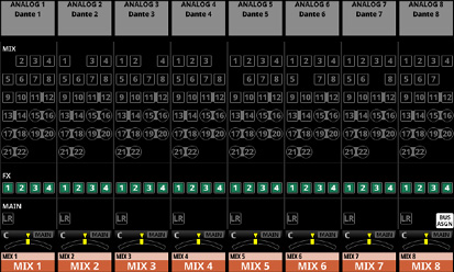
MIX 1–22 and MAIN L/R Master Module Home Screen
MIX 1–22 and MAIN L/R Master Module Home Screen
.jpg)
MIX 1–22 and MAIN L/R Master Module Home Screen details
OUTPUT area
If the PORT LABEL display mode is “USER”, the USER PORT LABEL (the port name set by the user) will be shown. If the USER PORT LABEL is undefined, the FIXED PORT LABEL will be shown. (See “DISPLAY MODE page”.)
If the PORT LABEL display mode is “FIXED”, the FIXED PORT LABEL will be shown for each port (for example, “ANALOG 1” or “Dante 1”). (See “DISPLAY MODE page”.)
This shows the output port assignment status.
If a Dante port that has a mounted SB-16D assigned is selected, “SB#[ID] [port number]” will be shown.

If it is a virtually-mounted SB-16D, ![]() will appear to the left of the port name.
will appear to the left of the port name.

If the module is stereo, the FIXED PORT LABEL for the output ports will appear split left and right and abbreviated as follows.

|
Output port name |
Output port name abbreviatio |
|
ANALOG |
AN |
|
Dante |
DA |
|
SLOT 1 |
S1 |
|
USB |
US |
When a module is stereo, if a Dante port that has a mounted SB-16D assigned is selected, “#[ID] [port number]” will be shown.

If it is a virtually-mounted SB-16D, the # background will be yellow.

Tap this area to open the MODULE (OUTPUT) Screen for the selected module. (See “MODULE (OUTPUT) Screen”.)
EQ area
This shows a graph of the EQ frequency response.
Tap this area to open the MODULE (EQ) Screen for the selected module. (See “MODULE (EQ) Screen”.)
GEQ area
This shows a graph of the GEQ frequency response.
Tap this area to open the MODULE (GEQ) Screen for the selected module. (See “MODULE (GEQ) Screen”.)
COMP/DUCKER area
This shows the response graphs and gain reduction meters of dynamics effects.
Tap this area to open the MODULE (COMP/DUCKER) Screen for the selected module. (See “MODULE (COMP/DUCKER) Screen”.)
INSERT indicator
The ![]() indicator is shown when the INSERT button is on for the MIX 1–22 module or MAIN L/R master module.
indicator is shown when the INSERT button is on for the MIX 1–22 module or MAIN L/R master module.
Level meters
This shows the level of the signal at the set metering point. (See “METERING POINT page” and “MIX 1–22 and MAIN L/R Master MODULE (OVERVIEW) Screens”.)
NOTE
If the selected module is stereo, a stereo level meter will be shown.
Each level meter has an overload indicator at its top. They will appear to light red when the signal level reaches or exceeds −0.00026 dBFS (16-bit full-scale value).
When a level overload occurs, the entire bar meter will light red.
The area below −60 dBFS at the bottom of the level meters will light when above −70 dBFS.
This shows the states of SEND settings to MIX 1–22 and FX 1–4 buses 4 at a time. This also shows the parameters of the Audio Follow Video function.
.jpg)
2.jpg)
This shows the MODULE LABEL set for the Main MODULE LABEL of the MIX 1–22 or FX RTN 1–4 module. (See “DISPLAY MODE page”.)
If the Main MODULE LABEL display mode is “USER” but the USER MODULE LABEL for that module is undefined, the FIXED MODULE LABEL will be shown (for example, “MIX 1” or “FX 1”).
This shows the PRE/POST setting used for MIX 1–22 and FX 1–4 buses.
|
No indicator |
Set to POST |
|
PRE |
Set to PRE |
These show the assignment state and send level to MIX 1–22 and FX 1–4 buses in AUX mode.
|
MIX 1–22 bus |
Shown in orange |
|
FX 1–4 bus |
Shown in green |
This will be gray when not assigned.
If a MIX or FX bus is stereo-linked, send levels will be shown with two bars.
Purple rounded buttons are shown when GROUP mode MIX 1–22 buses are ON. These appear but cannot be turned on/off on the Home Screen.
, and are not shown in the bus areas of the corresponding modules themselves. , and are also not shown in the FX 1–4 area of the MAIN L/R Master module.
.jpg)
Tap a SEND level to show the selection frame. When the selection frame is shown, corresponding LCD knobs can be used to adjust the SEND level shown.
Tap the SEND level while pressing the HOME key to set the SEND level for that bus to 0 dB. (See “16 - List of shortcut operations”.)
![]() button
button
Tap this button to show the selection window for the parameters shown in the SEND area.
Tap a parameter selection button to open the selected parameter group in the SEND area.
Tap the ![]() button at the top left of the selection window to close it.
button at the top left of the selection window to close it.
When the ![]() button is off (
button is off (![]() ), tapping a parameter selection button will automatically close this window.
), tapping a parameter selection button will automatically close this window.
When the ![]() button is on (
button is on (![]() ), tapping a parameter selection button will not close this window.
), tapping a parameter selection button will not close this window.
Tapping the AFV button will show 4 key parameters of the Audio Follow Video function in the SEND area.
2.jpg)
ON/OFF button for the Audio Follow Video function of the selected module
Tap this button to turn on/off the Audio Follow Video function of the selected module. When ON, buttons will be highlighted.
This shows the name of the AFV TRIGGER SOURCE selected on the AFV TRIGGER SOURCE SELECT Screen.
WAIT
This adjusts the amount of time until fading starts after receiving an AFV ON event.
RISE
This adjusts the amount of fade time until the ON LEVEL is reached after fading starts when an AFV ON event is received.
FALL
This adjusts the amount of fade time until the OFF LEVEL is reached after fading starts when an AFV OFF event is received.
Tapping – will make a selection frame appear. When a selection frame is shown, corresponding LCD knobs can be used to adjust the parameters shown.
When a selection frame is shown, tap this area to open the MODULE (Audio Follow Video) Screen for the selected module. (See “MODULE (Audio Follow Video) Screen”.)
Tap the AUTO MIXER button to show the parameters and meters for the AUTO MIXER function in the SEND areas of the CH 1–16 modules. In this case, the send areas will be empty for modules other than the CH 1–16 modules.
SEND/PAN button
Tap this button to open the MODULE (SEND/PAN) Screen. (See “MODULE (SEND/PAN) Screen”.)
Tap this button to switch from the normal display to the BUS ASSIGN display.
The SEND settings states for the MIX 1–22, FX 1–4 and MAIN L/R buses are shown as follows. (See “MODULE (SEND/PAN) Screen”.)
|
Icon |
SEND ON/OFF |
PRE/POST |
|
|
ON |
POST |
|
|
ON |
PRE |
|
|
OFF |
POST |
|
|
OFF |
PRE |
The BUS mode setting states for the MIX 1–22 modules are shown as follows. (See “BUS CONFIG page”.)
|
Icon |
Meaning |
|
|
MIX 1–22 modules when the BUS mode is AUX |
|
|
MIX 1–22 modules when the BUS mode is GROUP |
|
|
MIX 1–22 modules with Stereo Link setting on |
Tap the ![]() button when BUS ASSIGN display is active to return to normal display.
button when BUS ASSIGN display is active to return to normal display.
PAN area (MIX 1–22 modules only)
This shows the pan/balance setting of the signals sent to the MAIN L/R bus as well as the MAIN L/R bus assignment status.
Tap this area to show the selection frame. When the selection frame is shown, corresponding LCD knobs can be used to adjust the position/balance of the sent signals.
Tap this area while pressing the HOME key to set the tapped pan/balance setting to center (C). (See “16 - List of shortcut operations”.)
When the selection frame is shown, tap this area to open the MODULE (SEND/ PAN) Screen. (See “MODULE (SEND/PAN) Screen”.)
The module label at the left of the top line is shown according to the display mode set for the Sub MODULE LABEL on the DISPLAY MODE page. By default, the FIXED MODULE LABEL will be shown. (See “DISPLAY MODE page”.)
At the top right, the Mute Group assignment status is shown in the top line and the DCA assignment status is shown in the bottom line. Red numbers show the assigned Mute Group numbers. Yellow numbers show the assigned DCA numbers.
See “Mute Group Assign page” and “MODULE (OVERVIEW) Screen” for changing Mute Group assignments.
See “DCA Assign page” and “MODULE (OVERVIEW) Screen” for changing DCA assignments.
The bottom line shows the module label according to the display mode set for the Main MODULE LABEL on the DISPLAY MODE page. By default, the USER MODULE LABEL will be shown. (See “DISPLAY MODE page”.)
The MODULE LABEL area background color is the color set for the assigned module. See “Changing set module colors” to change set module colors.
Tap this area to open the MODULE (OVERVIEW) Screen. (See “MIX 1–22 and MAIN L/R Master MODULE (OVERVIEW) Screens”.)
NOTE
The following three display modes are available for the Main MODULE LABEL and Sub MODULE LABEL.
|
Display mode |
Explanation |
|
USER MODULE LABEL |
Module name set by user |
|
FIXED MODULE LABEL |
Predetermined names for each module (for example, “CH 1” and “MIX 1”) |
|
PORT LABEL |
Names of input and output ports |
The USER MODULE LABEL can be set on the MODULE LABEL Screen. (See “Setting and editing user module labels”.)
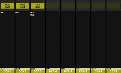
DCA Module Home Screen
.jpg)
DCA Module Home Screen details
DCA assignment display area
This shows the FIXED MODULE LABEL and USER MODULE LABEL of modules that have been assigned to that DCA.
Tap this area to open the DCA/Mute Group SETUP Screen DCA Assign page. (See “DCA Assign page”.)
MODULE LABEL area
The module label at the left of the top line is shown according to the display mode set for the Sub MODULE LABEL on the DISPLAY MODE page. By default, the FIXED MODULE LABEL will be shown. (See “DISPLAY MODE page”.)
At the top right, the Mute Group assignment status is shown in the top line and the DCA assignment status is shown in the bottom line. Red numbers show the assigned Mute Group numbers. Yellow numbers show the assigned DCA numbers.
See “Mute Group Assign page” for changing Mute Group assignments.
See “DCA Assign page” for changing DCA assignments.
The bottom line shows the module label according to the display mode set for the Main MODULE LABEL on the DISPLAY MODE page. By default, the USER MODULE LABEL will be shown. (See “DISPLAY MODE page”.)
The MODULE LABEL area background color is the color set for the assigned module. See “Changing set module colors” to change set module colors.
Tap this area to open the MODULE LABEL Screen where the USER MODULE LABEL and set module color can be changed. (See “MODULE LABEL screen”.)
NOTE
The following three display modes are available for the Main MODULE LABEL and Sub MODULE LABEL.
|
Display mode |
Explanation |
|
USER MODULE LABEL |
Module name set by user |
|
FIXED MODULE LABEL |
Predetermined names for each module (for example, “CH 1” and “MIX 1”) |
|
PORT LABEL |
Names of input and output ports |
The USER MODULE LABEL can be set on the MODULE LABEL Screen. (See “Setting and editing user module labels”.)
DCA Spill button
This button is shown when a module has been assigned to the corresponding DCA.
Tap this button to switch to DCA spill mode display. (See “DCA spill mode”.)
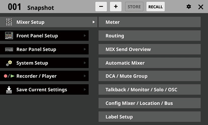
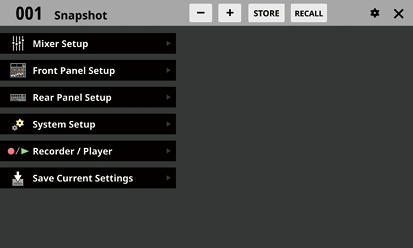
Open various settings screens and use snapshot functions from this screen.
Press the MENU key to open this on the right touchscreen.
.jpg)
Snapshot function area
This shows items related to the snapshot function.
See “Snapshot functions” for details about the snapshot function.
Menu item area
This shows menu items.
Tap a menu item to show its submenu items.
Submenu item area
This shows submenu items. If the submenu has 9 or more items, swipe the submenu area up and down to scroll it.
Tap a submenu item to open a settings screen.
![]() button
button
Tap this button to close the Menu Screen.
NOTE
On the Menu Screen, an ![]() icon sometimes appears with System Setup menu items and Version Information submenu items.
icon sometimes appears with System Setup menu items and Version Information submenu items.
In this case, an update is necessary for a device, application or this unit.
Check the Version Information Screen.(See “Version Information Screen”.)
In this example, will open the TALKBACK Setup Screen.
1.Press the MENU button to switch to the Menu Screen.
NOTE
When the Menu Screen is opened the first time after startup, submenu items will not be shown.
2.Tap “Front Panel Setup” in the menu item area to show its submenu items.
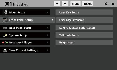
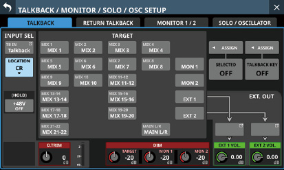
3.Tap “Talkback Setup” to open the TALKBACK page of the TALKBACK / MONITOR / SOLO / OSC SETUP screen.
The following is an overview of the various menu items.
|
Menu item |
Sub menu item |
Functions |
Page |
|
Mixer Setup |
Meter |
View various meters and set various meter display parameters |
|
|
Routing |
Make routing settings for the input/output ports and modules |
||
|
MIX Send Overview |
View and use a list of MIX 1–22 / FX 1–4 / MAIN L/R bus send settings |
||
|
Automatic Mixer |
AUTO MIXER settings |
||
|
DCA / Mute Group |
Make the following settings
|
||
|
Talkback / Monitor / Solo / OSC |
TALKBACK / RETURN TALKBACK / MONITOR output / SOLO / built-in oscillator settings |
||
|
Config Mixer / Location / Bus |
Make the following settings
|
||
|
Label Setup |
Label settings for modules and input/output ports |
||
|
Front Panel Setup |
User Key Setup |
Assign functions to the 18 USER KEYS |
|
|
User Key Extension |
Assign extended USER KEY functions |
||
|
Layer / Master Fader Setup |
Make the following settings
|
||
|
Talkback Setup |
Make talkback settings |
||
|
Brightness |
Set the brightness of the various displays |
||
|
Rear Panel Setup |
Dante Setup |
Set and view the status of the built-in Dante module and an SB-16D connected via the built-in Dante module |
|
|
ST 2110 Setup |
View the settings and states of IF-ST2110 cards installed in SLOT 1 or SLOT 2 on the rear panel. NOTE In the following circumstances, this sub menu item will appear gray and the ST 2110 Setup Screen will not open even if it is tapped.
|
||
|
Slot Setup |
Set various functions of expansion cards loaded in SLOT 1 and SLOT 2 |
||
|
WORD OUT Mode Setup |
Make WORD OUT jack output mode settings |
||
|
Network Setup |
Make Network settings |
||
|
FOOT SW Setup |
Assign footswitch functions |
||
|
GPIO Input Setup |
Assign functions to the GPIO input connector |
||
|
GPIO Output Setup |
Assign functions to the GPIO output connector |
||
|
System Setup |
Information |
View the state of the unit and error information |
|
|
Sync Clock |
Make the following settings
|
||
|
Preferences |
Make the following settings
|
||
|
Media Manage |
Display and format media data |
||
|
All System Data |
Save, load, back up and restore data for entire mixer |
||
|
Clock Adjust |
Set date and time of built-in clock |
||
|
Version Information |
View system version information |
||
|
Firmware Update |
Update the firmware |
||
|
Recorder / Player |
Recorder / Player |
Use built-in recorder/player |
|
|
Multi Track Recorder |
Use IF-MTR32 (multitrack recording) card installed in SLOT 1 or SLOT 2 on the rear panel NOTE In the following circumstances, this sub menu item will appear gray and the MULTI TRACK RECORDER Screen will not open even if it is tapped.
|
||
|
Save Current Settings |
Save current mixer settings in built-in memory (We recommend doing this before turning the unit off) |
||
Installing expansion cards (sold separately)
ATTENTION
Before installing or removing an expansion card (sold separately), disconnect the power cord from the outlet or the unit.
.jpg)
1.Remove the two screws from the plain panel and remove the panel itself. (If a different card is already installed, remove it.)
2.Insert the expansion card into the card slot. Align the edges of the expansion card with the white guides inside the slot and insert it securely. Push the expansion card in until its backplate reaches the rear panel of the unit, leaving no gap, and clicks into place. Do not force the card into the slot. If you cannot insert the card properly, remove it once and try reinserting it.
3.Use the two removed screws to secure the expansion card.
4.Turn the unit on, and check Menu Screen > Rear Panel Setup > SLOT SETUP screen to confirm that it has recognized the installed expansion card. (See “SLOT SETUP screen”.)
If “SLOT 1 (None)” or something similar appears, the expansion card might not be installed correctly or the screws might not be tightened securely. Insert the expansion card securely into the unit again.
CAUTION
Turn down the volume of the sound system connected to the unit before starting up or shutting down the unit.
Do not wear connected headphones when turning the unit on and off. Loud noises could damage the speakers or harm your hearing.
Before turning the power on
1.Minimize output faders along with monitor out and headphone volumes on this unit.
2.Minimize the output levels of audio sources and input levels of amplifiers connected to this unit.
Turning the power on
1.Use the POWER switch on the back of the unit to turn its power on.
After the unit starts and the startup screen is shown, the Home Screen will open.
2.Turn connected input audio source devices on.
3.Finally turn amplifiers on.
ATTENTION
After the power is turned on, an installed IF-ST2110 (ST 2110 card) needs about 2 1/2 minutes before it can input and output audio. This time will vary according to the setup of the network used by the IF-ST2110.
Turning the power off
Before turning the power off, minimize the levels of output faders along with monitor out and headphone volumes on this unit, and then follow the procedures above in reverse.
Failure to follow the correct order could result in clicking noises, for example, that might damage equipment.
CAUTION
Do not turn the power off or disconnect the power cord when the unit is operating (including recording, playing back, writing data to an SD card or USB flash drive, or saving settings to the internal memory). Doing so could cause proper recording to fail, recorded data to be lost, and sudden loud noises from monitoring equipment, which might damage the equipment, harm hearing or cause other trouble.
NOTE
We recommend executing the Save Current Settings command on the Menu Screen before turning the unit off. (See “Saving the current settings”.)
Setting the built-in clock date and time
This unit records file creation dates and times using its internal clock.
In addition, built-in clock date and time data is also used for recording file names as well as for file names when saving various library data and All System Data, for example.
For these reasons, we recommend setting the date and time accurately.
1.Tap Menu Screen > System Setup > Clock Adjust to open the CLOCK ADJUST Screen.
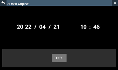
2.Tap the EDIT button to enable setting mode for this screen.
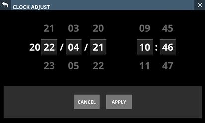
3.Swipe up and down to change values.
4.Tap the APPLY button to complete setting the date and time of the built-in clock.
NOTE
Tap the CANCEL button to exit setting mode.
Connecting and disconnecting SD cards and USB flash drives
SD cards and USB flash drives can be connected and disconnected whether the unit is on or off.
ATTENTION
Never disconnect an SD card or USB flash drive when it is being accessed, such as in the cases listed below.
Doing so could cause proper recording to fail, data to be lost, and sudden loud noises from monitoring equipment, which might damage the equipment, harm hearing or cause other trouble. Moreover, disconnecting during a firmware update could result in the unit becoming unable to start up or operate properly.
Recording (SD cards only)
Playing back
During IMPORT/EXPORT of snapshot data
During BACKUP/RESTORE of All System Data
During firmware updates (See “Firmware update procedures”.)
When an SD card or USB flash drive is being accessed with the BROWSE screen
NOTE
Insert an SD card into the SD card slot on the top of the unit so that its label faces right.
To remove an SD card, press it in gently to make it to come out and then pull it out completely.
SD card write protection switches
SD cards have write-protection switches that prevent writing new data to them.
.jpg)
If you slide the write-protection switch to the “LOCK” position, writing will not be possible. Move the write-protection switch to the unlocked position in order to record, erase and otherwise edit data on the card.
This unit also writes settings data for recording/playback folders on these media. Since setting information cannot be written to write-protected SD cards, settings for recording/playback folders will not be retained when the unit is restarted and performance will be otherwise affected.
Preparing SD cards and USB flash drives for use
Always use this unit to format the SD cards and USB flash drives to be used with it. (See “Media Manage Screen”.)
Operation of this unit might be affected when using an SD card or USB flash drive that has been formatted by a computer or other device.
ATTENTION
Formatting erases all the data on the SD card or USB flash drive.
SD cards formatted by this unit are optimized to improve performance during recording. Use this unit to format the SD cards to be used with it. Errors might occur when recording with this unit using an SD card formatted by a computer or other device.
SD cards and USB flash drives used by this unit
Lists of SD cards and USB flash drives that have been confirmed for use with this unit can be found on the TASCAM website.
Sonicview 16XP
https://tascam.jp/int/product/sonicview_16xp/docs
Sonicview 24XP
https://tascam.jp/int/product/sonicview_24xp/docs
Please use SD cards and USB flash drives included in these lists.
On this screen, the status of each audio clock is shown and audio synchronization settings and word clock output jack output mode settings can be made.
Tap Menu Screen > System Setup > Sync Clock to open this screen.
.jpg)
.jpg)
STATUS display area
This shows the status of each audio clock.
|
Item |
Explanation |
|
SYNC CLOCK |
This shows the synchronization status of this unit with the master clock (Locked/Unlocked/Regained) and the operation frequency (96kHz/48kHz/No Signal). |
|
WORD IN |
This shows the synchronization status of this unit with the WORD signal input through the WORD IN jack (Locked/Unlocked/Regained) and the operation frequency (actual measured value/No Signal). |
|
Dante |
This shows the synchronization status of this unit with the connected Dante system (Locked/Unlocked/Regained) and the operation frequency (actual measured value/No Signal). Tap the |
|
SLOT1 |
These show the names of the expansion cards in SLOT 1 and 2 and the synchronization statuses of this unit with them (Locked/Unlocked/Regained) and the operation frequency (actual measured value/No Signal). |
|
SLOT2 |
NOTE
The operation frequency will not be shown for SLOT 1 or SLOT 2 if it has an IF-MTR32 (multitrack recording) card installed.
Sync Clock buttons
These set the synchronization clock frequency of the digital input and output signals.
The selected button will be highlighted light blue.
Options: 48 kHz, 96 kHz (default)
NOTE
This unit will always operate internally at 96 kHz even when synchronized to a master clock that is 48 kHz.
Synchronization is possible even if the built-in Dante “Sampling rate” and the main unit “Sync Clock” settings are different.
Synchronization is not possible if the IF-DA64 (Dante) card “Sampling rate” is 44.1 or 88.2 kHz.
If the IF-DA64 (Dante) card “Sampling rate” is 48 or 96 kHz, synchronization is possible even if the main unit “Sync Clock” setting is different. (Set the IF-DA64 (Dante card) “Sampling rate” with Dante Controller.)
When the Clock Master is Dante, if the “Sampling rate” setting and Dante sampling rate are different, the following values will be shown for the operation frequency of the SYNC CLOCK.
When the internal Dante “Sampling rate” is “96 kHz” and Sync Clock is “48 kHz”, half the internal Dante measured value
When the internal Dante “Sampling rate” is “48 kHz” and Sync Clock is “96 kHz”, twice the internal Dante measured value
Clock Master buttons
These set the master clock used by this unit for audio synchronization. (default: INT)
A ![]() mark appears on the master clock being used.
mark appears on the master clock being used.
If the selected master clock is locked, the select button will be highlighted light blue.
If Sync Clock is “48 kHz” when the internal Dante “Sampling rate” is “96 kHz”, “1/2” will be shown at the top right of the Dante button.
If Sync Clock is “96 kHz” when the internal Dante “Sampling rate” is “48 kHz”, “x2” will be shown at the top right of the Dante button.
If the “Sampling rate” of an IF-DA64 (Dante) card installed in SLOT 1 or SLOT 2 is “96kHz” and Sync Clock is “48kHz”, “1/2” will be shown at the top right of the corresponding SLOT button.
If the “Sampling rate” of an IF-DA64 (Dante) card installed in SLOT 1 or SLOT 2 is “48kHz” and Sync Clock is “96kHz”, “×2” will be shown at the top right of the corresponding SLOT button.
If the selected external clock is unlocked, the unit will operate using the internal clock. In this case the ![]() will be shown on the INT button as the clock in use, while
will be shown on the INT button as the clock in use, while ![]() is shown on the selected button for the unlocked source. The selected button for the unlocked source will be highlighted red.
is shown on the selected button for the unlocked source. The selected button for the unlocked source will be highlighted red.
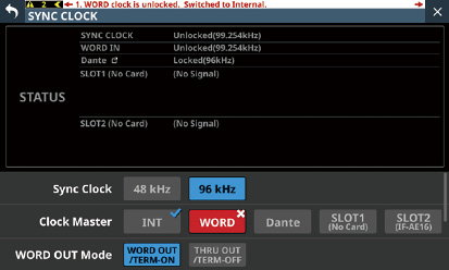
If synchronization becomes possible with an external clock after synchronization with it failed (Regain state), the ![]() will be shown on the INT button as the clock in use, while
will be shown on the INT button as the clock in use, while ![]() is shown on the selected button for the clock in a regain state. Tap the red-highlighted button with the
is shown on the selected button for the clock in a regain state. Tap the red-highlighted button with the ![]() mark to open a confirmation message for switching back to the selected master clock.
mark to open a confirmation message for switching back to the selected master clock.
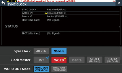
Tap the OK button to switch to synchronization with the selected external clock.
WORD OUT Mode buttons
These set the output mode of the WORD THRU/OUT connector on the back of the unit.
The selected button will be highlighted light blue.
|
Option |
Meaning |
|
WORD OUT/TERM-ON (default) |
This sets the signal output from the WORD THRU/OUT connector to WORD OUT and turns WORD IN connector termination resistance (75Ω) on. |
|
THRU OUT/TERM-OFF |
This sets the signal output from the WORD THRU/OUT connector to THRU output of the signal from the WORD IN connector and turns WORD IN connector termination resistance (75Ω) off. |
Clock Synchronous Type buttons
These can be shown by swiping up from the bottom of the SYNC CLOCK Screen.
These are settings for evaluating the synchronization status (locked/unlocked) of this unit and Dante signals.
|
Button |
Meaning |
|
Tight (default) |
Synchronization status is evaluated strictly. |
|
Loose |
Synchronization status is evaluated loosely. |
Setting the sampling frequency
1.Tap Menu Screen > System Setup > Sync Clock to open the SYNC CLOCK Screen.
2.Tap the button for the desired sampling frequency to set it.
A confirmation message will appear.
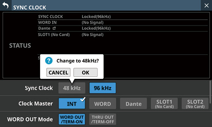
3.Tap the OK button to switch the sampling frequency.
ATTENTION
Switching the sampling frequency will mute the sound for a few seconds. Be aware of this timing when switching.
The unit's master clock can be set.
ATTENTION
When connecting multiple digital audio devices, set up the system so that it uses only one master clock.
1.Tap Menu Screen > System Setup > Sync Clock to open the SYNC CLOCK Screen.
2.Tap the button for the desired master clock to set it.
A confirmation message will appear.
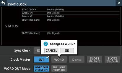
|
Button |
Use |
|
INT |
The unit's internal clock is used. |
|
WORD IN |
Synchronize with the word clock signal input through the WORD IN connector. |
|
Dante |
Synchronize with the clock of a connected Dante system. |
|
SLOT1 |
Synchronize with the digital signal clock received through SLOT 1. |
|
SLOT2 |
Synchronize with the digital signal clock received through SLOT 2. |
NOTE
If the SLOT1/SLOT2 button for the slot that has an IF-AE16 installed is tapped, a window will open that allows 8 pairs of input signals to be selected for the master clock. Tap the button for the input signal to set for the master clock.
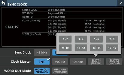
A confirmation message will appear.
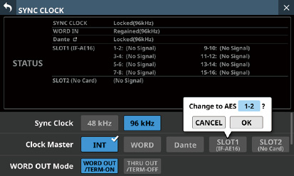
3.Tap the OK button to switch the master clock.
NOTE
If the SLOT 1 or SLOT 2 button is tapped when an IF-AN16/OUT or IF-MTR32 is installed in that slot, or if no expansion card has been installed in that slot, the following message will appear and the master clock will not be selected.
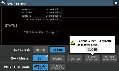
If the selected external clock is unlocked, the unit will operate using the internal clock. In this case the ![]() will be shown on the INT button as the clock in use, while
will be shown on the INT button as the clock in use, while ![]() is shown on the selected button for the unlocked source. The selected button for the unlocked source will be highlighted red.
is shown on the selected button for the unlocked source. The selected button for the unlocked source will be highlighted red.
When synchronization with the external master clock becomes possible again, a message like the one below will appear at the top of all touchscreens.
|
WORD clock regained. Can be re-synced to WORD. |
Tap this message to open the SYNC CLOCK Screen on the right touchscreen.
Tap the red-highlighted button with the ![]() mark to open a confirmation message for switching back to the selected master clock.
mark to open a confirmation message for switching back to the selected master clock.
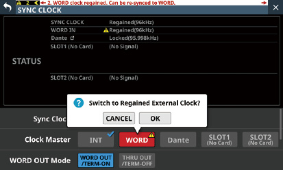
Tap the OK button to switch to synchronization with the selected external clock.
ATTENTION
When switching the master clock, noise might occur in the audio input and output.
Be aware of this when choosing when to change the master clock.
Make settings and view information as follows on this screen.
Cooling fan operation mode and speed settings
Cooling fan operation status display
Temperature value and status display for various locations
Snapshot STORE/RECALL confirmation setting
Digital Reference Level setting
Analog Reference Level setting
ON AIR Tally Inhibit setting
Mute Group LED Flash setting
Solo/Mute/Fader Speed setting
Auto Mixer Priority Inhibit setting
EQ parameters order setting
USB Keyboard type setting
Brightness settings for the various displays
Contrast settings for the channel screens
Tap any of the following menu screens to open this screen.
“Brightness“ in the Front Panel Setup menu
Preferences in the System Setup menu
.jpg)
.jpg)
.jpg)
.jpg)
FAN Status
This shows the cooling fan operation status and rotation speed.
|
Indicator |
FAN STATUS |
Meaning |
|
Green |
OK |
Normal |
|
Red |
FAILURE |
Malfunctioning |
FAN Control buttons
Use these to set the internal cooling fan operation mode.
The selected button will be highlighted.
|
Button |
Meaning |
|
Auto (default) |
Cooling fan operation will be controlled automatically. |
|
Manual |
FAN Speed ( |
Temperature Status
These show the temperature values of the SYSTEM (internal temperature), CPU and DSP.
|
Indicator |
Meaning |
|
Green |
Temperature is within normal range |
|
|
Temperature is not in normal range |
Snapshot STORE Confirmation switch
Set whether or not to show a confirmation message when storing snapshots.
When on, the sliding switch will appear highlighted.
NOTE
This can also be set by tapping the ![]() icon in the Snapshot function item area at the top of the Menu Screen and opening the CONFIRMATION settings window. (See “Snapshot functions”.)
icon in the Snapshot function item area at the top of the Menu Screen and opening the CONFIRMATION settings window. (See “Snapshot functions”.)
Snapshot RECALL Confirmation switch
Set whether or not to show a confirmation message when recalling snapshots.
When on, the sliding switch will appear highlighted.
NOTE
This can also be set by tapping the ![]() icon in the Snapshot function item area at the top of the Menu Screen and opening the CONFIRMATION settings window. (See “Snapshot functions”.)
icon in the Snapshot function item area at the top of the Menu Screen and opening the CONFIRMATION settings window. (See “Snapshot functions”.)
Digital Reference Level buttons
Use these to set the digital reference level.
The selected button will be highlighted.
Options:−9dBFS, −14dBFS, −16dBFS, −18dBFS, −20dBFS (default)
CH Display Contrast GANG button
This turns the Channel Screen contrast adjustment knob GANG function on or off (default).
When the GANG function is on, the button will appear highlighted.
When the GANG function is on, operating any LCD knob 1–3 will cause the contrast settings of all to follow, maintaining set differences.
CH Display Contrast knobs
Use these to adjust the contrasts of the channel screens.
Range: 0 – 60 (default: 40)
Turn an LCD knob to adjust 1 step at a time.
Press and turn an LCD knob to adjust 4 steps at a time.
|
LCD knob 1 |
Channels 1–8 |
|
LCD knob 2 |
Channels 9–16 |
|
LCD knob 3 |
Channels 17–24 (Sonicview 24XP only) |
NOTE
By turning an LCD knob while pressing the MENU key on the top of the unit, the contrast of the channel screen that corresponds to that knob can be adjusted. (See “16 - List of shortcut operations”.)
FAN Speed
When the operation mode of the cooling fan is “Manual”, its rotation speed can be adjusted.
Range: 1.0 – 10.0 (36 levels, default: 3.5)
Turn LCD knob 4 (lit blue) to adjust it.
Shortcut Help button
Tap this button to open a window that explains shortcut operations for adjusting the contrast of channel screens and brightness of the various displays.
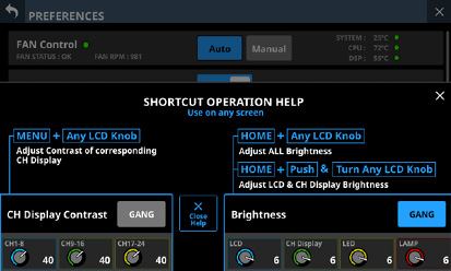
Tap ![]() at the top right of the SHORTCUT OPERATION HELP window or the Close Help button to close it.
at the top right of the SHORTCUT OPERATION HELP window or the Close Help button to close it.
LCD brightness knob
Turn LCD knob 5 (lit blue) to adjust the touchscreen brightness.
Range: 0 – 7 (default 6)
CH Display brightness knob
Turn LCD knob 6 (lit green) to adjust the channel screen brightness.
Range: 0 – 7 (default 6)
LED brightness knob
Turn LCD knob 7 (lit yellow) to adjust the indicator brightness.
Range: 0 – 7 (default 6)
LAMP brightness knob
Turn LCD knob 8 (lit red) to adjust the brightness of the lamp connected to the LAMP connector on the rear panel.
Range: 0 – 7 (default 6)
Scrollbar display
This scroll bar shows the position of the setting items currently shown on the screen relative to all items on the PREFERENCES Screen.
NOTE
To view setting items not shown on the screen, swipe the setting items area up and down to scroll the screen.
Brightness GANG button
This turns the brightness knods GANG function on (default) and off.
When the GANG function is on, the button will appear highlighted.
When the GANG function is on, operating any LCD knob 5–8 will cause the brightness settings of all to follow, maintaining set differences.
Analog Reference Level buttons
Use these to set the analog reference level.
The selected button will be highlighted.
Options: +6dBu, +4dBu (default), 0dBu
NOTE
Depending on the Digital Reference Level button setting, selection of some Analog Reference Level buttons will not be possible.
Buttons that cannot be selected will appear dark gray.
|
Analog Reference Level |
||||
|
+6dBu |
+4dBu |
0dBu |
||
|
Digital Reference Level |
−9dBFS |
|
|
|
|
−14dBFS |
|
|
|
|
|
−16dBFS |
|
|
|
|
|
−18dBFS |
|
|
|
|
|
−20dBFS |
|
|
|
|
 : Selectable
 : Not selectable
This switches on/off the ON AIR Tally Inhibit function that limits operations during ON AIR Tally input. (See “Operation restriction during ON AIR Tally input”.) (Default: OFF)
OA Tally Input port
This shows the name of the GPIO-IN port that has the ON AIR Tally Input function assigned.
Tap this area to switch to the GPIO-IN page of the USER DEFINED CONTROLS Screen. (See “GPIO-OUT page”.)
Mute Group LED Flash switch
This sets whether the MUTE buttons and the top panel MUTE keys flash for modules that have been muted by a Mute Group or DCA.
When ON, the sliding switch will appear highlighted.
|
Option |
Meaning |
|
ON (default) |
MUTE buttons and top panel MUTE keys will flash |
|
OFF |
MUTE buttons and top panel MUTE keys will not flash |
This shows the status of subjects of the ON AIR Tally Inhibit function.
Items that are selected as subjects of the ON AIR Tally Inhibit function will appear highlighted.
Items that are not selected as subjects of the ON AIR Tally Inhibit function will appear gray.
Tap this area to open a window where the selection status of the items subject to the ON AIR Tally Inhibit function can be set.
By tapping checkboxes to add check marks (![]() ), items can be selected as subject to operation restriction during ON AIR Tally input (See “Operation restriction during ON AIR Tally input”.).
), items can be selected as subject to operation restriction during ON AIR Tally input (See “Operation restriction during ON AIR Tally input”.).
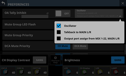
Mute Group Priority buttons
This switches the muting behavior of modules that are assigned to mute groups when the assigned groups are unmuted while the modules themselves are muted.
|
Option |
Meaning |
|
CH Mute (default) |
Corresponding modules continue to be muted |
|
Mute Group |
Corresponding modules are unmuted when their mute groups are unmuted |
DCA Mute Priority buttons
This switches the muting behavior of modules that are assigned to DCAs when the assigned DCAs are unmuted while the modules themselves are muted.
|
Option |
Meaning |
|
CH Mute (default) |
Corresponding modules continue to be muted |
|
DCA Mute |
Corresponding modules are unmuted when their DCAs are unmuted |
DCA Solo Priority buttons
If SOLO MODE is set to MIX, this switches the solo behavior of modules that are assigned to DCAs when solo is turned off on those DCAs while the modules themselves are soloed.
|
Option |
Meaning |
|
CH Solo (default) |
Corresponding modules continue to be soloed |
|
DCA Solo |
Corresponding modules are unsoloed when DCA solo is turned off |
Solo/Mute/Fader Speed buttons
These adjust the fade in/out speed when operating faders and turning soloing and muting on/off.
|
Option |
Explanation |
|
Default (default) |
This is the fastest fade in/out setting. |
|
Mid |
The speed of this fade in/out setting is between Default and Slow. |
|
Slow |
This is the slowest fade in/out setting. |
Auto Mixer Priority Inhibit switch
This turns on/off the Auto Mixer Priority Inhibit function, which restricts the following PRIORITY settings of the AUTO MIXER. (Default: ON)
TOP PRIORITY setting (See “ TOP PRIORITY ON/OFF button”.)
Group PRIORITY setting (See “ Group PRIORITY setting ON/OFF buttons”.)
Channel PRIORITY setting (See “ Channel PRIORITY setting ON/OFF button”.)
Switching this ON, turns OFF all the above PRIORITY settings of the AUTO MIXER, disabling their operation.
EQ parameters order buttons
Use these to select from 3 layouts for the EQ parameter display mode, which is shown framed in red on the MODULE (EQ) Screen.
The selected button will be highlighted.
Type A (default)
.jpg)
Type B
.jpg)
Type C
.jpg)
USB KEYBOARD TYPE buttons
Set the type of USB keyboard connected to the USB port on the top of the unit.
The selected button will be highlighted.
|
Button |
Meaning |
|
US |
US English keyboard |
|
JPN (default) |
Japanese keyboard |
Operation restriction during ON AIR Tally input
When “Oscillator” is subject to the ON AIR Tally Inhibit function
The OA Tally Inhibit switch is ON
The “Oscillator” checkbox is checked for items subject to the ON AIR Tally Inhibit function
If ON AIR Tally is input when all the above conditions are met, the built-in oscillator will turn off automatically (See “ OSCILLATOR button”.). Moreover, the built-in oscillator cannot be turned on during ON AIR Tally input.
When “Talkback to MAIN L/R” is subject to the ON AIR Tally Inhibit function
The OA Tally Inhibit switch is ON
The “Talkback to MAIN L/R” checkbox is checked for items subject to the ON AIR Tally Inhibit function
If ON AIR Tally is input when all the above conditions are met, the MAIN L/R button for the TALKBACK output to MAIN L/R will turn off automatically (See “ TARGET buttons”.). Moreover, TALKBACK output to MAIN L/R cannot be turned on during ON AIR Tally input.
When “Output port assign from MIX 1–22, MAIN L/R” is subject to the ON AIR Tally Inhibit function
The OA Tally Inhibit switch is ON
The “Output port assign from MIX 1–22, MAIN L/R” checkbox is checked for items subject to the ON AIR Tally Inhibit function
When all the above conditions are met, output port assignments for MIX 1–22 and MAIN L/R cannot be changed while ON AIR Tally is input.
NOTE
When the following two conditions apply, All System Data Cannot be loaded.
ON AIR Tally is input to GPIO-IN
The OA Tally Inhibit switch is ON
If Snapshot Recall is executed when ON AIR Tally is input to GPIO-IN, settings subject to ON AIR Tally Inhibit will become as follows.
1) Oscillator
ON AIR Tally is input to GPIO-IN
The OA Tally Inhibit switch is ON
The “Oscillator” checkbox is checked for items subject to the ON AIR Tally Inhibit function
If all the above conditions are met, the on/off state of the built-in oscillator signal will not be recalled when Snapshot Recall is executed.
If any of the above conditions are not met, the on/off state of the built-in oscillator signal will be recalled when Snapshot Recall is executed.
2) Talkback to MAIN L/R
This setting is not subject to snapshots.
For this reason, it will become as follows.
ON AIR Tally is input to GPIO-IN
The OA Tally Inhibit switch is ON
The “Talkback to MAIN L/R” checkbox is checked for items subject to the ON AIR Tally Inhibit function
If all the above conditions are met, the Talkback to MAIN L/R setting will be turned off when Snapshot Recall is executed.
If any of the above conditions are not met, the Talkback to MAIN L/R setting will not be changed when Snapshot Recall is executed.
3) Output port assign from MIX 1–22, MAIN L/R
ON AIR Tally is input to GPIO-IN
The OA Tally Inhibit switch is ON
The “Output port assign from MIX 1–22, MAIN L/R” checkbox is checked for items subject to the ON AIR Tally Inhibit function
If Snapshot Recall is executed when all the above conditions are met, routing settings from MIX 1–22 and MAIN L/R modules to output ports will be retained (not recalled).
View various meters and make settings for them on this screen.
Tap Menu Screen > Mixer Setup > Meter to open this screen.
.jpg)
NOTE
Using the User Defined Control function, this screen can also be opened with a USER KEYS, footswitch or the GPIO-IN. (See “USER DEFINED CONTROLS screen”.)
![]() button
button
Tap this button to return to the Menu Screen.
NOTE
If the ![]() button () on this screen appears highlighted (
button () on this screen appears highlighted (![]() ), tapping this button will not return to the Menu Screen.
), tapping this button will not return to the Menu Screen.
OVER Indicator
This will appear highlighted red if the signal level at a metering point of any module has overloaded. This will continue to appear highlighted for the PEAK HOLD time () set on this screen.
Tap this area to clear the highlighting of this indicator and the overload indicators of all level meters.
NOTE
They will appear to light red when the level reaches or exceeds −0.00026 dBFS (16-bit full-scale value).
PEAK CLEAR button
Tap this button to clear the peak hold indicators for the following level meters.
Peak indicators that are held below overload levels
Overload indicators for all level meters
NOTE
The OVER indicator () on this screen will not be cleared.
PEAK HOLD time display
This shows the level meter peak hold time.
Tap this area to open a window where the level meter peak hold time can be set.
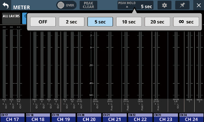
Options: OFF(no hold), 2 sec, 5 sec (default), 10 sec, 20 sec, ∞ sec (hold until cleared)
![]() button
button
Tap this button to open the METER SETUP Screen. (See “METER SETUP screen”.)
![]() button
button
Tap this button, highlighting it, to disable the METER Screen ![]() () and
() and ![]() () buttons as shown below and prevent the METER Screen from being closed.
() buttons as shown below and prevent the METER Screen from being closed.
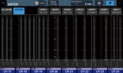
In this state, the METER Screen will stay open even if the HOME key on the top of the unit is pressed.
The screen can still be switched, however, by conducting the following operation.
Tap the ![]() () button to open the METER SETUP Screen.
() button to open the METER SETUP Screen.
Press the MENU key on the top panel to switch to the Menu Screen.
Press the HOME and MENU keys together to open the LOCK SETUP Screen.
Press the SEL key on the top panel to switch to the MODULE Screen.
Tap the Home Screen MODULE LABEL area () at the bottom of this screen to open the MODULE (OVERVIEW) Screen.
Tap the ![]() button when it is highlighted (
button when it is highlighted (![]() ) to open a confirmation message.
) to open a confirmation message.
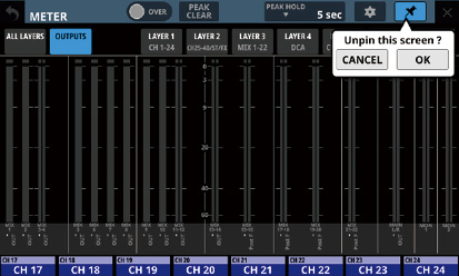
Tap the OK button to end highlighting of the ![]() button, enabling closing of the METER Screen.
button, enabling closing of the METER Screen.
![]() button
button
Tap this button to return to the Home Screen.
NOTE
If the ![]() button () on this screen appears highlighted (
button () on this screen appears highlighted (![]() ), tapping this button will not return to the Home Screen.
), tapping this button will not return to the Home Screen.
Page selection buttons
The button for the currently selected page is highlighted and corresponding level meters are shown in the meter area ().
Tap one of these buttons to switch to showing the corresponding level meters.
Meter Area
The level meters are shown for the page with the highlighted selection button.
|
Page name |
Contents |
|
ALL LAYERS |
This shows level meters for the modules assigned to all of the 7 layers on one line per layer. The MODULE LABEL set as the Main MODULE LABEL will be shown at the bottom of each level meter. (See “DISPLAY MODE page”.) |
|
OUTPUTS |
This shows level meters for MIX 1–22 and MAIN L/R Master modules and the MONITOR OUT. The FIXED MODULE LABEL, the MODULE LABEL set as the Main MODULE LABEL (See “DISPLAY MODE page”.) and the Metering Point will be shown at the bottom of each level meter. |
|
LAYER1 |
This shows level meters for the modules assigned to the corresponding layer. The FIXED MODULE LABEL, the MODULE LABEL set as the Main MODULE LABEL (See “DISPLAY MODE page”.) and the Metering Point name will be shown at the bottom of each level meter. |
|
LAYER2 |
|
|
LAYER3 |
|
|
LAYER4 |
|
|
LAYER5 |
|
|
LAYER6 |
|
|
LAYER7 |
Two meters will be shown for stereo modules.
Each level meter has an overload indicator at its top. They will appear to light red when the signal level reaches or exceeds −0.00026 dBFS (16-bit full-scale value).
When a level overload occurs, the entire bar meter will light red.
The area below −60 dBFS at the bottom of the level meters will light when above −70 dBFS.
Home screen MODULE LABEL area
This shows the same information as the MODULE LABEL area on the Home Screen for modules assigned to the right touchscreen on the current layer (module labels according to the display mode set for the Sub MODULE LABEL and Main MODULE LABEL (See “DISPLAY MODE page”.), Mute Group assignment or DCA assignment).
Tap this area to open the MODULE (OVERVIEW) Screen. (See “MODULE (OVERVIEW) Screen”.)
Make the following settings on this screen.
METERING POINT page
Set the metering points for each module type.
METER HEADROOM page
Set the point where level meter colors change on each screen.
Tap ![]() on the METER Screen to open this screen.
on the METER Screen to open this screen.
.jpg)
OVER Indicator
This has the same function as the OVER indicator on the METER Screen. (See “METER screen”.)
PEAK CLEAR button
This has the same function as the PEAK CLEAR button on the METER Screen. (See “METER screen”.)
PEAK HOLD time display
This has the same function as the PEAK HOLD time display on the METER Screen. (See “METER screen”.)
![]() button
button
Tap this button to return to the METER Screen. (See “METER screen”.)
Page selection buttons
Tap these buttons to switch the page shown.
Home screen MODULE LABEL area
This shows the MODULE LABEL area of the right touchscreen Home Screen. (See “METER screen”.)
Set the metering points for each module type on this page.
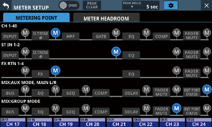
Tap ![]() icons to set metering points.
icons to set metering points.
When a metering point is selected, that ![]() icon will appear highlighted (
icon will appear highlighted (![]() ).
).
|
Module type |
default |
|
CH 1–40 module |
PRE HPF |
|
ST IN 1–2 module |
PRE EQ |
|
FX RTN 1–4 module |
FX OUTPUT |
|
MIX 1–22 and MAIN L/R Master modules when the BUS mode is AUX |
OUTPUT* |
|
MIX 1–22 modules when the BUS mode is GROUP |
POST FADER |
*Metering Point “OUTPUT” setting explanation
For the following module types, this is the Metering Point setting when the ![]() icon to the right of “OUT PORT STATUS” is lit (
icon to the right of “OUT PORT STATUS” is lit ( ![]() ).
).
MIX: AUX MODE, MAIN L/R
MIX: GROUP MODE
NOTE
These can also be set on the MODULE (OVERVIEW) screens for each module using Metering Point buttons. (See “MODULE (OVERVIEW) Screen”.)
When the Metering Point is OUTPUT*, and the corresponding bus has not been assigned to an output port (not being output from the unit), meters will not be shown.
On this page, set the point where level meter colors change on each screen.
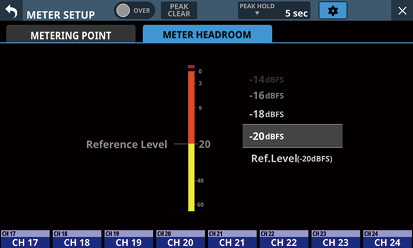
Options: −9dBFS, −14dBFS, −16dBFS, −18dBFS, −20dBFS, Ref.Level (default)
Swipe the options up and down to select the point where colors change.
On this screen, set the lock function to prevent this unit from being controlled from its front panel or an external device.
Preventing only selected operations is also possible.
Press and hold the HOME and MENU keys on the top panel together for 5 seconds to open the screen on the right touchscreen.
.jpg)
ALL LOCK button
Tap this button to switch it ON and OFF. (Default: OFF)
When ON, this button will be highlighted and all operations subject to locking will be prohibited.
SELECTED LOCK status
This shows the ON/OFF status of SELECTED LOCK which prevents the operation of selected items. (Default: OFF)
![]() icon
icon
Tap this icon to open the SELECTED LOCK settings window.
List of items subject to locking
This shows whether each item subject to locking is locked or not.
Unlocked items are shown with white letters.
Locked items, which are prohibited from operation, are shown with a lock mark and black letters.
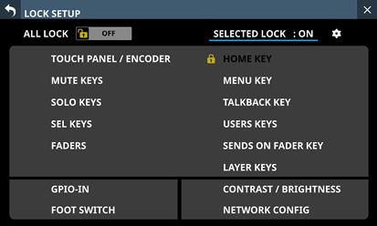
.jpg)
CHECK ALL button
This puts checks (![]() ) into the checkboxes of all items subject to locking.
) into the checkboxes of all items subject to locking.
UNCHECK ALL button
This removes checks (![]() ) from the checkboxes of all items subject to locking.
) from the checkboxes of all items subject to locking.
SELECTED LOCK button
When a check (![]() ) is in at least one of the checkboxes for items subject to locking, tap this button to switch it ON/OFF.
) is in at least one of the checkboxes for items subject to locking, tap this button to switch it ON/OFF.
When ON, this button will be highlighted and the selected operations subject to locking will be prohibited.
When this is ON, the CHECK ALL () and UNCHECK ALL () buttons as well as the checkboxes for items subject to locking will be hidden and cannot be operated.
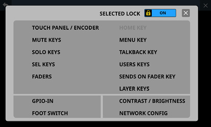
Appearance when HOME KEY item set as subject to locking
![]() button
button
Tap this button to close the SELECTED LOCK settings window.
Selection list for subjects of individual locking
Use this to switch the lock function on/off.
Tap the checkboxes of items you want to select as subject to locking to put checks (![]() ) in them.
) in them.
NOTE
Lockable controls and operations
LCD touchscreen and LCD knob operations
MUTE key operations
SOLO key operations
SEL key operations
Fader operations
HOME key operations
MENU key operations
TALKBACK key operations
USER KEY operations
SENDS ON FADER key operations
LAYER KEY operations
GPIO-IN operations
FOOT SWITCH operations
Various parameter setting change operations for Contrast and Brightness
Setting changes on the Network Setup Screen (See “Network Setup screen”.)
The following controls and operations will not be locked.
Headphone volume
MONITOR OUT volume
TALKBACK volume
POWER switch
Pressing HOME and MENU keys simultaneously
Touchscreen operations on the LOCK SETUP Screen
Make the following settings on this screen.
CH 1–40 CONFIG page
CH 1–40 stereo link settings
DIRECT OUT POINT settings
DELAY POINT settings
INSERT POINT unified settings
LOCATION CONFIG page
LOCATION settings for CH 1–40, ST IN 1-2, FX RTN 1–4 and MIX 1–22
LOCATION settings for MONITOR 1/2
BUS CONFIG page
BUS MODE settings
MIX 1–22 stereo link settings
PAN LINK settings
Tap Menu Screen > Mixer Setup > Config Mixer / Location / Bus to open this screen.
.jpg)
Page selection buttons
Tap these buttons to switch the page shown.
CH 1–40 MODULE LABEL button area
This shows the CH 1–40 module labels according to the set Sub MODULE LABEL and Main MODULE LABEL display modes. (See “DISPLAY MODE page”.)
Tap these buttons to open the MODULE LABEL Screen where the USER MODULE LABEL and set module color can be changed. (See “MODULE LABEL screen”.)
STEREO LINK button area
These show the stereo link settings states of the CH 1–40 modules.
Tap these buttons to turn the stereo link setting on and off (default) for the CH 1–40 modules.
When the stereo link is on, the button will appear highlighted.
Scroll knob and scrollbar
Drag the scrollbar left and right to show CH 1–40 modules that are not shown on the screen. The screen can also be scrolled by turning LCD knob 8.
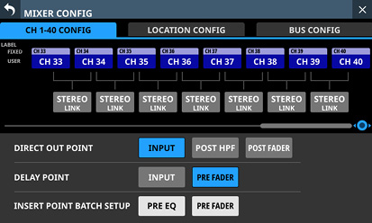
NOTE
The screen can also be scrolled by swiping left and right between the CH 1–40 module MODULE LABEL area () and the STEREO LINK button area ().
DIRECT OUT POINT buttons
Tap these buttons to change all direct out points for the CH 1–40 modules at the same time.
Options: INPUT (default), POST HPF, POST FADER
DELAY POINT buttons
Tap these buttons to change the delay function insert position for the CH 1–40 modules at the same time.
INSERT POINT BATCH SETUP buttons
These change all the insert points at once for the CH 1–40 modules, which can be set individually on the MODULE (OVERVIEW) Screen.
Tapping a button will open a setting change confirmation message.
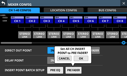
Tap the OK button to change the insert points for all CH 1–40 modules at the same time.
.jpg)
Page selection buttons
Tap these buttons to switch the page shown.
MODULE LABEL area for CH 1–40 / ST IN 1–2 / FX RTN / MIX modules
This shows the module labels according to the set Sub MODULE LABEL and Main MODULE LABEL display modes for the CH 1–40, ST IN 1–2, FX RTN and MIX modules. (See “DISPLAY MODE page”.)
Tap these buttons to open the MODULE LABEL Screen where the USER MODULE LABEL and set module color can be changed. (See “MODULE LABEL screen”.)
Module Location setting area
Tap these buttons to change the Location settings of the CH 1–40, ST IN 1–2, FX RTN and MIX modules.
|
Button |
Function |
|
CR |
Set Location to Control Room (CR). |
|
ST |
Set Location to Studio (ST). |
|
NONE (default) |
Leave Location unset. |
Scroll knob and scrollbar
Drag the scrollbar left and right to show CH 1–40, ST IN 1–2, FX RTN and MIX modules that are not shown on the screen. The screen can also be scrolled by turning LCD knob 8.
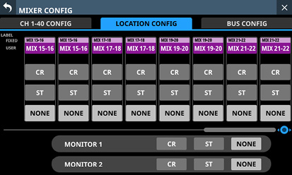
NOTE
The screen can also be scrolled by swiping left and right between the CH 1–40, ST IN 1–2, FX RTN and MIX module LABEL area () and the module Location setting area ().
Tap these buttons to change the Location settings of MONITOR 1 and MONITOR 2.
|
Button |
Function |
|
CR |
Set Location to Control Room (CR). |
|
ST |
Set Location to Studio (ST). |
|
NONE (default) |
Leave Location unset. |
NOTE
If the Location of any monitors are set to “ST”, the Monitor Exclusive button (See “ Monitor Exclusive button”.) cannot be switched on and the MONITOR 1/2 exclusive selection function cannot be used.
To use the MONITOR 1/2 exclusive function, switch the monitor Location setting to “CR” or “NONE”.
Automatic muting of monitor signals using the Location function
With the Location function, the muting of monitoring signals is as follows, which is useful for solo DJs.
Just before an input signal, or bus that it passes through, set to the same Location (excluding NONE) as MONITOR 1 or MONITOR 2 begins to be output from the MAIN L/R bus when no such signal had been output before, the corresponding monitoring signal will be automatically muted.
Just after all input signals, and buses that they pass through, set to the same Location (excluding NONE) as MONITOR 1 or MONITOR 2 stop being output from the MAIN L/R bus, the corresponding monitoring signal will be automatically unmuted.
If on route from the input signal to the MAIN L/R bus, it passes through a bus set to a different Location, muting of the monitoring signal will not be controlled.
Examples:
CH 1 module (Location: CR)  MIX 1 module (Location: CR) MAIN L/R bus: Monitoring signal will be muted/unmuted
CH 1 module (Location: CR) MIX 1 module (Location: ST) MAIN L/R bus: Monitoring signal will not be muted/unmuted
CH 1 module (Location: CR) MIX 1 module (Location: NONE) MAIN L/R bus: Monitoring signal will not be muted/unmuted
If the conditions are fulfilled as a result of the following parameter operations, muting of monitoring signals will be controlled.
Changing the FADER LEVEL to/from −∞ dB (including level operation using a DCA layer)
Switching MUTE on/off (including DCA/Mute Group muting operations)
Turning on/off SEND or MAIN L/R assignments
Changing the SEND LEVEL to/from −∞ dB
SEND PRE/POST switching
MODULE Library recall
Snapshot Recall
Changing Location settings
Changing bus mode settings (AUX/GROUP)
Changing CH MUTE / PRE-SEND LINK settings
Changing DCA assignments
Changing Mute Group assignments
All System Data Load
The following routes are supported when searching for routes from inputs to the MAIN L/R bus.
Supported routes
Route without buses
Input module MAIN
Routes that pass through 1 bus
Input module MIX MAIN
Input module FX MAIN
Routes that pass through 2 buses
Input module MIX MIX MAIN
Input module MIX FX MAIN
Input module FX MIX MAIN
Route that passes through 3 buses
Input module MIX FX MIX MAIN
The following routes are not supported.
If a route is unsupported, the judgment is that it does not reach the MAIN L/R bus and so is not output from the MAIN L/R bus. For this reason, operating a module parameter of an unsupported route will function toward unmuting the monitoring signal.
Unsupported routes
The following routes that pass through 3 buses
Input module MX MX MX MAIN
Input module MX MX FX MAIN
Input module FX MX MX MAIN
Input module FX MX FX MAIN
Routes that pass through 4 or more buses
.jpg)
Page selection buttons
Tap these buttons to switch the page shown.
MIX 1–22 MODULE LABEL area
This shows the MIX 1–22 module labels according to the set Sub MODULE LABEL and Main MODULE LABEL display modes. (See “DISPLAY MODE page”.)
Tap these buttons to open the MODULE LABEL Screen where the USER MODULE LABEL and set module color can be changed. (See “MODULE LABEL screen”.)
BUS MODE area
Tap these buttons to change the bus modes of MIX 1–22 modules.
|
Button |
Function |
|
AUX |
Set the MIX bus that corresponds to the button to function as an AUX bus. SEND level, on/off and PRE/POST settings can be made from each module to AUX mode buses. (PRE/POST is only for input modules.) |
|
GROUP |
Set the MIX bus that corresponds to the button to function as a GROUP bus. Only on/off can be set for modules to GROUP mode buses. They are always sent POST FADER. |
NOTE
When BUS is changed from GROUP to AUX, the setting color of corresponding MIX 1–22 modules will change to orange.
When BUS is changed from AUX to GROUP, the setting color of corresponding MIX 1–22 modules will change to purple.
AUX bus counts
This shows the number of modules set to AUX in the BUS MODE area.
“ST” shows the number of AUX mode module pairs that have the stereo link setting on.
“MONO” shows the number of AUX mode modules that have the stereo link setting off.
GROUP bus counts
This shows the number of modules set to GROUP in the BUS MODE area.
“ST” shows the number of GROUP mode module pairs that have the stereo link setting on.
“MONO” shows the number of GROUP mode modules that have the stereo link setting off.
STEREO LINK button area
These show the stereo link settings states of the MIX 1–22 modules.
Tap these buttons to turn the stereo link setting on/off for the MIX 1–22 modules.
When the stereo link is on, the button will appear highlighted.
PAN LINK button area
These buttons appear when MIX 1–22 module stereo link settings are on and the BUS mode is AUX.
When the PAN LINK setting is on, the AUX bus pan/balance (SEND PAN) setting is linked to the MAIN L/R bus pan/balance setting.
Scroll knob and scrollbar
Drag the scrollbar left and right to show MIX 1–22 modules that are not shown on the screen. The screen can also be scrolled by turning LCD knob 8.
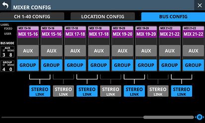
NOTE
The screen can also be scrolled by swiping left and right between the MIX 1–22 module LABEL area () and the PAN LINK button area ().
The following settings can be made on this screen.
User Key page
Functions can be assigned to USER KEYS A–F and USER KEYS 1–12.
Tap Menu Screen > Front Panel Setup > User Key Setup to open this page.
Foot Switch page
Functions can be assigned to the footswitch.
Tap Menu Screen > Rear Panel Setup > FOOT SW Setup to open this page.
GPIO-IN page
Functions can be assigned to the GPIO input connector of this unit or of an SB-16D connected through the built-in Dante.
Tap Menu Screen > Rear Panel Setup > GPIO Input Setup to open this page.
GPIO-OUT page
Functions can be assigned to the GPIO output pins of an SB-16D connected to this unit or through the built-in Dante.
Tap Menu Screen > Rear Panel Setup > GPIO Output Setup to open this page.
The settings for keys and connectors are made in operation setting tables on each page.
Tap one of the four page selection buttons to open that page. (See “USER DEFINED CONTROLS screen structure”.)
The functions that can be assigned on these pages are as follows.
User Key, Foot Switch and GPIO-IN pages
|
Function |
Parameter1 |
Parameter2 |
Parameter3 |
Function explanation |
|
|
Snapshot |
Select |
Next |
Increase by one the number of the Snapshot available for STORE/RECALL shown at the top of the Menu Screen. (See “Snapshot functions”.) |
||
|
Prev |
Decrease by one the number of the Snapshot available for STORE/RECALL shown at the top of the Menu Screen. (See “Snapshot functions”.) |
||||
|
No. |
001–128/P001 |
This makes the specified Snapshot number shown at the top of the Menu Screen the target for STORE/RECALL. (See “Snapshot functions”.) |
|||
|
Recall |
Selected |
Recall the Snapshot available for RECALL shown at the top of the Menu Screen. (See “Snapshot functions”.) |
|||
|
Next |
Switch the number of the Snapshot available for RECALL shown at the top of the Menu Screen to the number of the next Snapshot that is not an existing preset, and then recall it. (See “Snapshot functions”.) |
||||
|
Prev |
Switch the number of the Snapshot available for RECALL shown at the top of the Menu Screen to the number of the next lower Snapshot that is not an existing preset, and then recall it. (See “Snapshot functions”.) |
||||
|
No. |
001–128/P001 |
Recall a snapshot by number. (See “Snapshot functions”.) |
|||
|
+Target Key |
Press this simultaneously with a key that has Function set to Snapshot and Parameter 1 set to Target to recall that set snapshot number. (See “Snapshot functions”.) |
||||
|
Snapshot |
Store |
Selected |
Store the Snapshot available for STORE shown at the top of the Menu Screen. (See “Snapshot functions”.) |
||
|
No. |
001–128 |
Store a snapshot by number. (See “Snapshot functions”.) |
|||
|
+Target Key |
Press this simultaneously with a key that has Function set to Snapshot and Parameter 1 set to Target to store in that set snapshot number. (See “Snapshot functions”.) However, even when Function is set to Snapshot and Parameter 1 is set to Target, this will not work if the key assigned to Parameter 2 as “Next” or “Prev” is pressed at the same time. |
||||
|
Target |
Selected |
Press simultaneously with a key assigned to a +Target Key function to STORE to or RECALL from the Snapshot number shown at the top of the Menu Screen. |
|||
|
Next |
Press this key simultaneously with a key set to Function: Snapshot, Parameter 1: RECALL and Parameter 2: +Target Key to recall the next Snapshot that is not an existing preset after the one shown at the top of the Menu Screen. |
||||
|
Prev |
Press this key simultaneously with a key set to Function: Snapshot, Parameter 1: RECALL and Parameter 2: +Target Key to recall the next Snapshot that is not an existing preset before the one shown at the top of the Menu Screen. |
||||
|
No. |
001–128/P001 |
Press simultaneously with a key assigned to a +Target Key function to STORE to or RECALL from the specified Snapshot number. |
|||
|
Undo/Redo |
Undo Color (USER KEY only) |
Redo Color (USER KEY only) |
Undo/redo Snapshot RECALL operations. (See “Snapshot functions”.) When undoing is possible, the USER KEYS that this function is assigned to will light in the color set by Parameter 2: Undo Color. When redoing is possible, the USER KEYS that this function is assigned to will light in the color set by Parameter 3: Redo Color. (Parameters 2 and 3 can only be set to USER KEYS.) |
||
|
Monitor |
MONITOR 1 MONITOR 2 |
Source select |
1 (MAIN L/R) 2 (MIX 15–16) 3 (MIX 1) 4 (MIX 11–12) 5 (Dante 31–32) 6 (USB 31–32) |
When pressed individually, this selects a single monitoring source with the number specified by Parameter 3 for the monitor specified by Parameter 1. (See “ When multiple buttons that have this function assigned are pressed simultaneously, the ADD function will be turned on, so multiple monitoring sources pressed at the same time can be selected together. This allows multiple selected monitoring sources to be mixed and monitored together. USER KEYS will light when in selected status. |
|
|
Monitor |
MONITOR 1 MONITOR 2 |
MUTE |
Turn muting on/off for the monitoring signal specified by Parameter 1. (See “ USER KEYS will light when this is on. |
||
|
DIM |
Turn dimming on/off for the monitoring signal specified by Parameter 1. (See “ USER KEYS will light when this is on. |
||||
|
PFL to MON |
Turn on/off PFL to MON for the monitor specified by Parameter 1. (See “ USER KEYS will light when this is on. |
||||
|
AFL to MON |
Turn on/off AFL to MON for the monitor specified by Parameter 1. (See “ USER KEYS will light when this is on. |
||||
|
MON 2 FOLLOW MON 1 FOLLOW |
Turn on/off FOLLOW for the monitor specified by Parameter 1. (See “ USER KEYS will light when this is on. |
||||
|
ADD |
Turn on/off the ADD function for the monitor specified by Parameter 1. (See “ USER KEYS will light when this is on. |
||||
|
STEREO/MONO |
MONO COLOR (USER KEY only) |
Switch between STEREO and MONO for the monitor specified by Parameter 1. When set to STEREO, it will light with the color set for the USER KEY. When set to MONO, it will light with the color set by Parameter 3: MONO COLOR. |
|||
|
Exclusive |
MON 1/MON 2 |
MON 2 COLOR (USER KEY only) |
Alternate the monitor exclusive selection between MONITOR 1 and MONITOR 2.
|
||
|
MONITOR 1 MONITOR 2 |
Press this key to exclusively select the monitors set with Parameter 2.
|
||||
|
SOLO |
PFL/AFL |
AFL COLOR (USER KEY only) |
This switches the SOLO TYPE between PFL and AFL. When SOLO TYPE is PFL, it will light with the color set for the USER KEY. When SOLO TYPE is AFL, it will light with the color set for Parameter 2: AFL Color. |
||
|
OSC |
ON/OFF |
Turn on/off the internal oscillator signal. USER KEYS will light when this setting is on. |
|||
|
Talkback |
TALKBACK Key to MIX1 – to MIX22 to MAIN L/R to Selected BUS to MON 1 to MON 2 to EXT 1 to EXT 2 |
Single Key +SLATE Key |
|
||
|
SLATE Key |
|||||
|
Return Talkback |
to Selected BUS to MON 1 to MON 2 to EXT OUT to SOLO |
Single Key + SLATE Key |
|
||
|
SLATE Key |
|||||
|
AUTO MIXER |
TOP PRIORITY |
This turns on/off the TOP PRIORITY setting of the AUTO MIXER. USER KEYS will light when this is on. |
|||
|
PRIORITY A-D |
This turns on/off the group PRIORITY setting of the AUTO MIXER. USER KEYS will light when this is on. |
||||
|
LO CUT A-D ON/OFF |
This turns on/off the LO CUT button for the AUTO MIXER (A/B/C/D) group. USER KEYS will light when this is on. |
||||
|
GROUP A-D ON/OFF |
This turns on/off the AUTO MIXER (A/B/C/D) group. USER KEYS will light when this is on. |
||||
|
AUTO MIXER ON/OFF |
This turns on/off the AUTO MIXER function. USER KEYS will light when this is on. |
||||
|
AFV |
ON/OFF |
This turns all the Audio Follow Video functionality on/off. (See “MODULE (Audio Follow Video) Screen”.) USER KEYS will light when this is on. |
|||
|
MODULE ON/OFF |
CH1–40 STIN1–2 FXRTN1–4 MIX1–22 MAIN L/R |
This turns the Audio Follow Video functionality on/off for individual modules. USER KEYS will light when this is on. |
|||
|
Trigger Source Emulate (USER KEY only) |
GPIO-IN 1–8 #--- GPIO-IN 1–8 #--- GPIO-IN 1–8 #--- GPIO-IN 1–8 #--- GPIO-IN 1–8 FOOT SW |
Unlatch Latch |
AFV trigger input by the trigger source (GPIO-IN port or FOOT SW) set by Parameter 2 is emulated by USER KEY operation. If Parameter 3 is set to “Unlatch”, it will operate as follows.
If Parameter 3 is set to “Latch”, it will operate as follows.
USER KEYS will light while they are emulating the closed state of the Trigger Source selected by Parameter 2. |
||
|
LED Indication (USER KEY only) |
GPIO-IN |
GPIO-IN 1–8 #--- GPIO-IN 1–8 #--- GPIO-IN 1–8 #--- GPIO-IN 1–8 #--- GPIO-IN 1–8 |
Closed-LIT Open-LIT |
|
|
|
GPIO-OUT |
GPIO-OUT 1–8 #--- GPIO-OUT 1–8 #--- GPIO-OUT 1–8 #--- GPIO-OUT 1–8 #--- GPIO-OUT 1–8 |
Closed-LIT Open-LIT |
|||
|
ON AIR Tally |
When the GPIO-IN port specified for OA Tally Input becomes shorted (Closed), corresponding USER KEYS light. |
||||
|
LED Indication (USER KEY only) |
MON DIM Status |
TB DIM (MON 1) |
When DIM becomes enabled by a TALKBACK operation for MONITOR 1, corresponding USER KEYS light. |
||
|
TB DIM (MON 2) |
When DIM becomes enabled by a TALKBACK operation for MONITOR 2, corresponding USER KEYS light. |
||||
|
TB DIM/DIM (MON 1) |
When MONITOR 1 DIM is enabled by TALKBACK operation or DIM button, corresponding USER KEYS light. (See “ |
||||
|
TB DIM/DIM (MON 2) |
When MONITOR 2 DIM is enabled by TALKBACK operation or DIM button, corresponding USER KEYS light. (See “ |
||||
|
TB DIM (MON 1/MON 2) |
When DIM becomes enabled by a TALKBACK operation for MONITOR 1 or MONITOR 2, corresponding USER KEYS light. |
||||
|
ALL |
When MONITOR 1 or MONITOR 2 DIM is enabled by TALKBACK operation or DIM button, corresponding USER KEYS light. (See “ |
||||
|
OA Tally Input (GPIO-IN only) |
This function can only be assigned to one GPIO-IN port. If the GPIO-IN port that this function is assigned to becomes shorted (Closed), ON AIR Tally Inhibit operation will be implemented in accordance with settings for ON AIR Tally Inhibit subjects (See “ |
||||
|
Sends On Fader |
MIX1–22 FX1–4 |
Turn the Sends On Fader mode for the selected bus on/off. (See “SENDS ON FADER screen”.) |
|||
|
DCA Spill |
DCA 1–8 |
This turns on/off DCA spill mode. USER KEYS will light when this is on. NOTE This cannot be turned on if no module is assigned to the corresponding DCA. |
|||
|
Recorder/Player |
Recorder |
REC |
This has the following functions, which are the same as the
|
||
|
PAUSE |
This has the following functions, which are the same as the
|
||||
|
STOP |
This has the following functions, which are the same as the
|
||||
|
Recorder/Player |
Player |
PLAY/PAUSE |
PAUSE COLOR (USER KEY only) |
This starts/pauses playback of the player on the right side of the RECORDER/PLAYER Screen.
|
|
|
PLAY |
This has the same functions as the
|
||||
|
PAUSE |
This has the following functions, which are the same as the
|
||||
|
STOP |
This has the following functions, which are the same as the
|
||||
|
FAST FORWARD |
This has the same functions as the
|
||||
|
REWIND |
This has the same functions as the
|
||||
|
Recorder/Player |
Player |
FILE SKIP NEXT |
This has the same functions as the
|
||
|
FILE SKIP PREV |
This has the same functions as the
|
||||
|
DIRECT PLAY |
1–100 (file number) |
Pressing the key will start playback from the beginning of the file, which is specified by number with Parameter 3, in the player on the right side of the RECORDER/PLAYER Screen. USER KEYS will light when the player is playing the file with the specified number. |
|||
|
MTR |
REC |
This has the following functions, which are the same as the
|
|||
|
PLAY |
This has the following functions, which are the same as the
|
||||
|
MTR |
STOP |
This has the following functions, which are the same as the
|
|||
|
PAUSE |
This has the following functions, which are the same as the
|
||||
|
FAST FORWARD |
This has the following functions, which are the same as the
|
||||
|
REWIND |
This has the following functions, which are the same as the
|
||||
|
TAKE SKIP NEXT |
This has the following functions, which are the same as tapping the When the MTR operation mode is LIVE RECORDING MODE or VIRTUAL SOUND CHECK MODE:
When the MTR operation mode is OVERDUB MODE:
|
||||
|
MTR |
TAKE SKIP PREV |
This has the following functions, which are the same as tapping the When the MTR operation mode is LIVE RECORDING MODE or VIRTUAL SOUND CHECK MODE:
When the MTR operation mode is OVERDUB MODE:
|
|||
|
MARK SKIP NEXT |
This has the following functions, which are the same as tapping the
|
||||
|
MARK SKIP PREV |
This has the following functions, which are the same as tapping the
|
||||
|
Undo/Redo |
Undo Color (USER KEY only) |
Redo Color (USER KEY only) |
This has the following functions, which are the same as tapping the UNDO/REDO button on the MULTI TRACK RECORDER Screen.
|
||
|
Punch IN/OUT |
Use this to punch in/out in the MULTI TRACK RECORDER. When the MTR operation mode is OVERDUB MODE and at least one REC READY is on, press this when playing to punch in and start recording. Press during recording to punch to punch out and continue playback. |
||||
|
SET MARK |
This has the following functions, which are the same as tapping the SET MARK button on the MULTI TRACK RECORDER Screen.
|
||||
|
SOUND CHECK |
SOUND CHECK |
This has the same function as tapping the SOUND CHECK button on the MULTI TRACK RECORDER Screen.
|
|||
|
YES |
Pressing this button when an MTR SOUND CHECK confirmation message is shown has the same function as tapping the YES button in that message. |
||||
|
MTR |
IN-OUT |
SET IN |
This has the same function as tapping the SET IN button on the MULTI TRACK RECORDER Screen.
|
||
|
SET OUT |
This has the same function as tapping the SET OUT button on the MULTI TRACK RECORDER Screen.
|
||||
|
I-O CLEAR |
This has the same function as tapping the CLEAR button on the MULTI TRACK RECORDER Screen.
|
||||
|
REPEAT |
This has the same function as tapping the repeat mode setting button on the MULTI TRACK RECORDER Screen.
|
||||
|
REHEARSAL |
This has the same function as tapping the REHEARSAL button on the MULTI TRACK RECORDER Screen.
|
||||
|
Input Source |
CH1–40 STIN1–2 |
A B Toggle |
Switch the input source for the module specified by Parameter 1. If Parameter 1 is set to “ALL”, “Toggle” cannot be selected for Parameter 2. |
||
|
ALL |
A B |
||||
|
Insert On/Off |
CH1–40 MIX1–22 MAIN L/R |
This turns on/off the INSERT of the module specified with Parameter 1. USER KEYS will light when the corresponding setting is on. |
|||
|
Send On/Off |
CH1–40 STIN1–2 FXRTN1–4 MIX1–22 MAIN L/R |
MIX1–22 FX1–4 MAIN L/R |
This turns ON/OFF the SEND from the module specified with Parameter 1 to the bus specified with Parameter 2. USER KEYS will light when the corresponding setting is on. |
||
|
Mute |
CH1–40 STIN1–2 FXRTN1–4 MIX1–22 MAIN L/R DCA1–8 Mute Group1–8 |
Mute - LIT Unmute - LIT (USER KEY only) |
|
||
|
Closed - Mute Closed - Unmute (FOOT Switch/GPIO-IN) |
|
||||
|
FX Send Mute |
FX1–4 |
Mute - LIT Mute - UNLIT |
Turn on/off MUTE processing for the SEND to the specified FX1-4. If Parameter 2 is “Mute-LIT”, the USER KEY will light when muted. |
||
|
Tap Tempo |
FX1–4 |
Delay1–3 |
Use to tap the tempo to input the DELAY TIME when the selected effect type is DELAY. (See “MODULE (FX) Screen”.) When the effect type is any delay other than “DELAY LCR”, set Parameter 2 to “Delay 1”. When the effect type is “DELAY LCR”, set Parameter 2 as follows. |
||
|
Desired parameter |
Parameter 2 setting |
||||
|
DELAY TIME L |
Delay1 |
||||
|
DELAY TIME C |
Delay2 |
||||
|
DELAY TIME R |
Delay3 |
||||
|
Screen |
Information |
ERROR COLOR (USER KEY only) |
This opens the INFORMATION Screen on the right touchscreen. In this case, the last open page of the INFORMATION Screen will be shown again if the unit is functioning properly. The ERROR page will open if an error or alert is occurring with the unit. When any page of the INFORMATION Screen is open, pressing corresponding USER KEYS will close the screen. Regardless of whether the INFORMATION Screen is open, corresponding USER KEYS will be lit/unlit as follows.
|
||
|
Snapshot |
This opens the SNAPSHOT Screen on the right touchscreen and lights corresponding USER KEYS. When this screen is open, pressing corresponding USER KEYS will close it. |
||||
|
METER |
ALL LAYERS OUTPUTS LAYER1–7 LAST TAB |
Show the page of the METER Screen specified by Parameter 2 on the rightmost touchscreen and light the corresponding USER KEYS. When this screen is open, pressing a corresponding USER KEYS will close it. |
|||
|
TB/Monitor/OSC |
TALKBACK |
Show the TALKBACK page of the TALKBACK / MONITOR / SOLO / OSC SETUP Screen on the rightmost touchscreen and light corresponding USER KEYS. When this screen is open, pressing corresponding USER KEYS will close it. |
|||
|
RETURN TALKBACK |
Show the RETURN TALKBACK page of the TALKBACK / MONITOR / SOLO / OSC SETUP Screen on the rightmost touchscreen and light corresponding USER KEYS. When this screen is open, pressing corresponding USER KEYS will close it. |
||||
|
MONITOR 1/2 |
Show the MONITOR 1/2 page of the TALKBACK / MONITOR / SOLO / OSC SETUP Screen on the rightmost touchscreen and light corresponding USER KEYS. When this screen is open, pressing corresponding USER KEYS will close it. |
||||
|
SOLO/OSCILLATOR |
Show the SOLO/OSCILLATOR page of the TALKBACK / MONITOR / SOLO / OSC SETUP Screen on the rightmost touchscreen and light corresponding USER KEYS. When this screen is open, pressing a corresponding USER KEYS will close it. |
||||
|
Screen |
ROUTING |
Input Port Input Module Output Module Output Port Analog GAIN |
This opens the ROUTING Screen on the right touchscreen. |
||
|
SEND OVERVIEW |
MIX1–22 FX1–4 MAIN L/R |
LCD L LCD C (Sonicview 24XP only) LCD R |
This will show the Send Overview Screen for the bus specified by Parameter 2 on the touchscreen specified by Parameter 3, and corresponding USER KEYS will light. When this screen is open, pressing corresponding USER KEYS will close it. |
||
|
MODULE(FX) |
FX RTN 1–4 |
LCD L LCD C (Sonicview 24XP only) LCD R |
This will show the MODULE (FX) for the FX specified by Parameter 2 on the touchscreen specified by Parameter 3, and corresponding USER KEYS will light. When this screen is open, pressing corresponding USER KEYS will close it. |
||
|
HOME |
SEND 1st BLOCK SEND 2nd BLOCK SEND 3rd BLOCK SEND 4th BLOCK SEND 5th BLOCK SEND 6th BLOCK SEND 7th BLOCK BUS ASSIGN AUTO MIXER AFV |
This will show the Home Screen with, as specified by Parameter 2, the 4 Send buses of a block, all the Send buses, the AUTO MIXER settings or the Audio Follow Video function parameter settings on the touchscreen, and corresponding USER KEYS will light. |
|||
|
AUTO MIXER |
This opens the AUTOMATIC MIXER Screen on the right touchscreen and lights corresponding USER KEYS. When this screen is open, pressing corresponding USER KEYS will close it. |
||||
|
RECORDER/PLAYER |
Show the RECORDER PLAYER Screen on the right touchscreen and light the corresponding USER KEYS. When this screen is open, pressing a corresponding USER KEYS will close it. |
||||
|
MULTI TRACK RECODER |
Show the MULTI TRACK RECORDER Screen on the right touchscreen and light the corresponding USER KEYS. When this screen is open, pressing a corresponding USER KEYS will close it. |
||||
|
USER KEY EXTENSION |
This opens the USER KEY EXTENSION Screen on the right touchscreen. |
||||
|
ST2110 |
Audio Network Config. HOME |
This opens the ST2110 SETUP Screen on the right touchscreen. |
|||
|
Label |
Module Main Label Module Sub Label |
User |
This sets the display mode of the MODULE LABEL specified by Parameter 1 to “USER”. Corresponding USER KEYS will light when the MODULE LABEL display mode is “USER”. |
||
|
Fixed |
This sets the display mode of the MODULE LABEL specified by Parameter 1 to “FIXED”. Corresponding USER KEYS will light when the MODULE LABEL display mode is “FIXED”. |
||||
|
Port Label |
This sets the display mode of the MODULE LABEL specified by Parameter 1 to “PORT LABEL”. Corresponding USER KEYS will light when the MODULE LABEL display mode is “PORT LABEL”. |
||||
|
Rotation |
Pressing this key will cycle through the display mode of the MODULE LABEL specified by Parameter 1 in order: USER, FIXED, PORT LABEL. |
||||
|
Label |
Port Label |
User |
This sets the PORT LABEL display mode to “USER”. Corresponding USER KEYS will light when the PORT LABEL display mode is “USER”. |
||
|
Fixed |
This sets the PORT LABEL display mode to “FIXED”. Corresponding USER KEYS will light when the PORT LABEL display mode is “PORT LABEL”. |
||||
|
Toggle |
Pressing this key will alternate the PORT LABEL display mode between “USER” and “FIXED”. |
||||
|
User Defined Controls Lib |
Recall |
Current |
This recalls the current library (most recently stored/recalled library). |
||
|
Next |
This recalls data for the library that is one after the current (most recently stored/recalled) library and is not a preset. |
||||
|
Prev |
This recalls the data for the library that is one before the current (most recently stored/recalled) library and is not a preset. |
||||
|
No. |
001-128/P001 |
This recalls the library with the specified number. |
|||
|
+TargetKey |
Press this key and the key set by Parameter 1: Target at the same time to recall data from the library number set with Target Parameter 2. |
||||
|
Store |
Current |
This stores data by overwriting the current library (most recently stored/recalled library). Nothing will happen if the current library is P001 (Preset). |
|||
|
No. |
001-128 |
This stores data to the specified library. |
|||
|
+TargetKey |
Press this key and the key set by Parameter 1: Target at the same time to store data to the library number set with Target Parameter 2. However, this will do nothing if pressed at the same time as a key with Target Parameter 2 set to “Next” or “Prev”. |
||||
|
Target |
Current |
Use this with RECALL/STORE Parameter 2: +TargetKey to specify the target. |
|||
|
Next |
|||||
|
Prev |
|||||
|
No. |
001-128/P001 |
||||
|
Undo/Redo |
Undo Color (USER KEY only) |
Redo Color (USER KEY only) |
Use this to undo/redo library recall operations. When undoing/redoing is possible, the key will light in the corresponding set color. (Parameters 2 and 3 can only be set to USER KEYS.) |
||
NOTE
Foot Switch/GPIO-IN:
When one of the functions below is assigned, the selected function will become active while a low level signal is input. Moreover, if the same function is assigned to multiple GPIO-IN and/or footswitches, the function will be activated when any one of those signals is Low level. The function will be deactivated only when all the signals from the assigned GPIO-IN and/or footswitches are High level (OR operation).
If any of the following functions are assigned when the unit starts up, when All System Data is loaded, when a Snapshot is recalled, or when a User Defined Control Library is recalled, the corresponding function will become active/inactive according to the GPIO-IN connector / Foot Switch status.
Monitor Mute
Monitor DIM
Monitor PFL to MON
Monitor AFL to MON
Monitor FOLLOW
Monitor Stereo/Mono (Mono at Low level)
SOLO (AFL at Low level)
OSC
Talkback
Return Talkback
AUTO MIXER
AFV
OA Tally Input
Insert On/Off
Send On/Off
Mute
FX Send Mute
When one of the functions below is assigned, the selected function will operate if a low level signal of 50 ms or longer is input.
Snapshot
User Key Library
Monitor Source Select
Monitor Exclusive MONITOR 1
Monitor Exclusive MONITOR 2
Sends On Fader
Recorder/Player
MTR
Input Source
Tap Tempo
Screen
Label
When one of the functions below is assigned, the selected function will be toggled on/off if a low level signal of 50 ms or longer is input.
Monitor ADD
Monitor Exclusive MON 1/MON 2
Excluding the current snapshot, snapshots stored using a USER key, FOOTSWITCH or GPIO-IN are named “USER KEY” followed by a three-digit slot number (for example, “USER KEY 018”).
When the Function is set to Snapshot and Parameter 2 is set to No, if Parameter 3 matches the current Snapshot number, the corresponding USER KEY will light.
When a USER key with an MTR function set is operated, the MULTI TRACK RECORDER Screen will open on the right touchscreen. When MTR operation mode is active, however, the MULTI TRACK RECORDER Screen will not open if it does not have a button with the corresponding function.
GPIO-OUT page
|
Function |
Parameter1 |
Parameter2 |
Parameter3 |
Function explanation |
||
|
Fader Start |
CH1–40 STIN1–2 FXRTN1–4 MIX1–22 MAIN L/R |
Pulse 30msec Pulse 50msec Pulse 100msec Pulse 150msec Pulse 200msec Pulse 250msec Pulse 300msec |
NORMAL-Open NORMAL-Closed |
A pulse signal will be output with the width set by Parameter 2 when the status of the specified module becomes as follows. When Parameter 3 is “NORMAL-Open”, a pulse signal shaped like
|
||
|
Fader Stop |
CH1–40 STIN1–2 FXRTN1–4 MIX1–22 MAIN L/R |
Pulse 30msec Pulse 50msec Pulse 100msec Pulse 150msec Pulse 200msec Pulse 250msec Pulse 300msec |
NORMAL-Open NORMAL-Closed |
A pulse signal will be output with the width set by Parameter 2 when the status of the specified module becomes as follows. When Parameter 3 is “NORMAL-Open”, a pulse signal shaped like
|
||
|
Fader Start/Stop |
CH1–40 STIN1–2 FXRTN1–4 MIX1–22 MAIN L/R |
Alternate |
NORMAL-Open NORMAL-Closed |
The signal level output will change depending on the MUTE and FADER level states of the specified module. When MUTE is off for the specified module and the FADER level is above the fader start level setting value, if Parameter 3 is NORMAL-Open, low level signal output will be latched. When Parameter 3 is “NORMAL-Closed”, high level signal output will be latched. |
||
|
Parameter 3 |
When MUTE is on for the specified module or the FADER level is not above the fader start level setting value |
When MUTE is off for the specified module and the FADER level is above the fader start level setting value |
||||
|
NORMAL-Open |
High level (Open) is output |
Low level (Closed) is output |
||||
|
NORMAL-Closed |
Low level (Closed) is output |
High level (Open) is output |
||||
|
Mute Status |
CH1–40 STIN1–2 FXRTN1–4 MIX1–22 MAIN L/R DCA1–8 Mute Group1–8 |
SINGLE |
Mute-Closed Unmute-Closed |
|
||
|
GPIO-OUT Group1–8 |
AND OR |
Mute-Closed Unmute-Closed |
This outputs the muting status of the group of multiple modules assigned to the GPIO-OUT Group 1–8 specified with Parameter 1. See “STATUS OUT GROUP SETUP screen” for details about setting groups.
|
|||
|
Solo Status |
CH1–40 STIN1–2 FXRTN1–4 MIX1–22 MAIN L/R |
SINGLE |
ON-Closed Off-Closed |
|
||
|
GPIO-OUT Group1–8 |
AND OR |
ON-Closed Off-Closed |
This outputs the solo status of the group of multiple modules assigned to the GPIO-OUT Group 1–8 specified with Parameter 1. See “STATUS OUT GROUP SETUP screen” for details about setting groups.
|
|||
|
Solo Clear |
LIT-Closed UNLIT-Closed |
|
||||
|
USER KEY OUT |
USER KEY A–F USER KEY 1–12 |
Pulse 30msec Pulse 50msec Pulse 100msec Pulse 150msec Pulse 200msec Pulse 250msec Pulse 300msec Alt. Latch Alt. Unlatch |
NORMAL-Open NORMAL-Closed |
If a USER KEY designated by Parameter 1 is pressed, the GPIO-OUT connector output status will be changed.
|
||
|
GPIO-IN OUT |
GPIO-IN 1–8 #--- GPIO-IN 1–8 #--- GPIO-IN 1–8 #--- GPIO-IN 1–8 #--- GPIO-IN 1–8 |
NORMAL INVERT |
|
|||
|
MTR Status |
REC PLAY STOP PAUSE FAST FORWARD REWIND TAKE SKIP NEXT TAKE SKIP PREV |
These output the MTR status from the GPIO-OUT port. While selected, they output LOW level. |
||||
|
AUTO MIXER Tally |
TOP PRIORITY |
NORMAL- Open NORMAL- Closed |
This outputs AUTO MIXER TOP PRIORITY on/off states from the GPIO-OUT port. When TOP PRIORITY is ON and Parameter 2 is “NORMAL-Open”, low level signal (Closed) output will be latched. When Parameter 3 is “NORMAL-Closed”, high level signal (Open) output will be latched. |
|||
|
PRIORITY A-D |
NORMAL- Open NORMAL- Closed |
This outputs AUTO MIXER (A/B/C/D) group PRIORITY on/off states from the GPIO-OUT port. When AUTO MIXER (A/B/C/D) group PRIORITY is ON and Parameter 2 is “NORMAL-Open”, low level signal (Closed) output will be latched. When Parameter 3 is “NORMAL-Closed”, high level signal (Open) output will be latched. |
||||
|
LO CUT A-D ON/OFF |
NORMAL- Open NORMAL- Closed |
This outputs AUTO MIXER (A/B/C/D) group LO CUT button on/off states from the GPIO-OUT port. When AUTO MIXER (A/B/C/D) group LO CUT is ON and Parameter 2 is “NORMAL-Open”, low level signal (Closed) output will be latched. When Parameter 3 is “NORMAL-Closed”, high level signal (Open) output will be latched. |
||||
|
GROUP A-D ON/OFF |
NORMAL- Open NORMAL- Closed |
When AUTO MIXER (A/B/C/D) group is ON and Parameter 2 is “NORMAL-Open”, low level signal (Closed) output will be latched. When Parameter 2 is “NORMAL-Closed”, high level signal (Open) output will be latched. |
||||
|
AUTO MIXER ON/OFF |
NORMAL- Open NORMAL- Closed |
When AUTO MIXER is ON and Parameter 2 is “NORMAL-Open”, low level signal (Closed) output will be latched. When Parameter 2 is “NORMAL-Closed”, high level signal (Open) output will be latched. |
||||
|
Monitor Status |
MONITOR 1 MONITOR 2 |
1–6 |
This outputs the monitoring source selection status for the monitor specified by Parameter 1 from the GPIO-OUT. When the monitoring source with the number specified by Parameter 2 is selected, low level (Closed) will be output. |
|||
|
Mute |
This outputs whether the monitor specified by Parameter 1 is muted or unmuted from the GPIO-OUT. When muted, low level (Closed) will be output. |
|||||
|
Add |
This outputs the ADD function on/off status for the monitor specified by Parameter 1 from the GPIO-OUT. When the ADD function is on, low level (Closed) will be output. |
|||||
USER DEFINED CONTROLS screen structure
.jpg)
User Key page
.jpg)
GPIO-OUT page
Page selection buttons
Tap these buttons to switch the page shown.
![]() button
button
Tap this button to open a window where the footswitch polarity and fader start level can be set. (See “Setting the footswitch polarity” and “Fader Start Level setting”.)
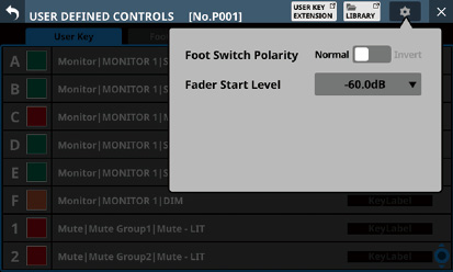
Control names and ![]() buttons (User Key page only)
buttons (User Key page only)
The colors that USER KEYS light when their functions are activated can be set.
Tap these buttons to open a color palette window.
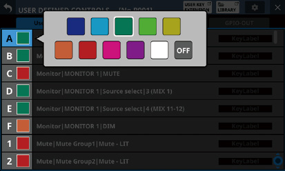
Tap a color in the color palette to close the window and change the control name display color.
Set function names
The show the names of functions that have been assigned to the controls.
Tap this area to open the control setting table for the controls.
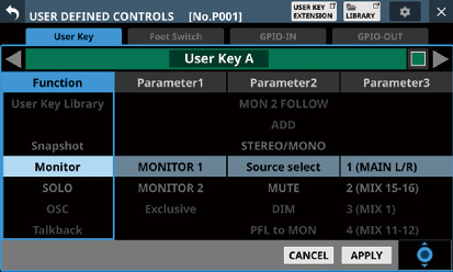
Scroll knob and scrollbar
These appear when all selectable options cannot be shown on the display at the same time.
Drag the bar to scroll the visible options. The options can also be scrolled by swiping up and down on the control name () and set function name () area as well as by turning LCD knob 8.
USER KEY EXTENSION button
Tap this button to open the USER KEY EXTENSION Screen. (See “USER KEY EXTENSION screen”.)
LIBRARY button
Tap this button to open the USER DEFINED CONTROLS LIBRARY Screen. (See “USER DEFINED CONTROLS LIBRARY Screen”.)
Key Label display area (User Key page only)
Tap the label display area to open the USER LABEL (User Key) Screen.
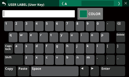
Key labels can have up to 8 characters.
Tap the ![]() button to return to the USER DEFINED CONTROLS Screen.
button to return to the USER DEFINED CONTROLS Screen.
Tap the Enter button to move to the next item that can have a label assignment.
Library number
This shows the current library number, which was last subject to storing and recalling.
STATUS OUT GROUP button (GPIO-OUT page only)
Tap this button to open the STATUS OUT GROUP SETUP Screen. (See “STATUS OUT GROUP SETUP screen”.)
Control setting on USER DEFINED CONTROLS Screen
.jpg)
![]() /
/![]() buttons
buttons
Tap these buttons to switch the control that is being edited.
Control name area
This shows the name of the currently selected control.
![]() button (User Key page only)
button (User Key page only)
The colors that USER KEYS light when their functions are activated can be set.
Tap these buttons to open a color palette window.
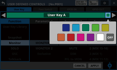
Tap a color in the color palette to close the window and change the control name display color.
Function list
Functions that can be set for the controls and their parameters are shown in a 4-column list.
Tap a column and select the setting to be changed. The selected column will be highlighted.
To change a setting, swipe the list up and down in the highlighted column. The setting can also be changed by turning LCD knob 8 (lit light blue).
CANCEL button
Tap this button to cancel setting changes and return to the top USER DEFINED CONTROLS Screen.
APPLY button
Tap this button to apply setting changes and return to the top USER DEFINED CONTROLS Screen.
Scroll knob icon
This icon shows that LCD knob 8 (lit light blue) can be used to scroll.
On this page, functions can be assigned to USER KEYS A–F and USER KEYS 1–12.
Tap Menu Screen > Front Panel Setup > User Key Setup to open this page.
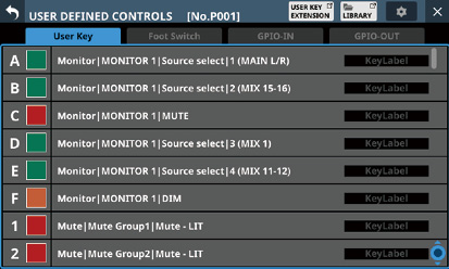
User Key page when setting controls
The factory default settings are as follows.
|
Key |
Lit color |
Assigned function |
|
USER KEYS A |
Green |
Monitor | MONITOR 1 | Source select | 1 (MAIN L/R) |
|
USER KEYS B |
Green |
Monitor | MONITOR 1 | Source select | 2 (MIX 15-16) |
|
USER KEYS C |
Red |
Monitor | MONITOR 1 | MUTE |
|
USER KEYS D |
Green |
Monitor | MONITOR 1 | Source select | 3 (MIX 1) |
|
USER KEYS E |
Green |
Monitor | MONITOR 1 | Source select | 4 (MIX 11-12) |
|
USER KEYS F |
Orange |
Monitor | MONITOR 1 | DIM |
|
USER KEYS 1 |
Red |
Mute | Mute Group1 | Mute - LIT |
|
USER KEYS 2 |
Red |
Mute | Mute Group2 | Mute - LIT |
|
USER KEYS 3 |
Red |
Mute | Mute Group3 | Mute - LIT |
|
USER KEYS 4 |
Red |
Mute | Mute Group4 | Mute - LIT |
|
USER KEYS 5 |
Orange |
Sends On Fader | MIX1 |
|
USER KEYS 6 |
Orange |
Sends On Fader | MIX2 |
|
USER KEYS 7 |
Orange |
Sends On Fader | MIX3 |
|
USER KEYS 8 |
Orange |
Sends On Fader | MIX4 |
|
USER KEYS 9 |
Orange |
Sends On Fader | MIX5 |
|
USER KEYS 10 |
Orange |
Sends On Fader | MIX6 |
|
USER KEYS 11 |
Orange |
Sends On Fader | MIX7 |
|
USER KEYS 12 |
Orange |
Sends On Fader | MIX8 |
Functions can be assigned to the footswitch on this page.
Tap Menu Screen > Rear Panel Setup > FOOT SW Setup to open this page.
.jpg)
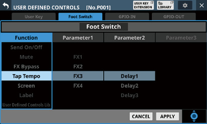
Foot Switch page when setting controls
AFV indicator
If Foot Switch is selected as a trigger source for the Audio Follow Video function “AFV” will be shown here in blue.
Checking whether multiple functions have been assigned to the Foot Switch is possible.
The factory default setting is “Tap Tempo | FX3 | Delay1”.
Setting the footswitch polarity
This unit was designed to be used with momentary footswitches that must be pushed to function (shorted when pushed). Since the polarity can be reversed, however, push-to-break (shorted with not pushed) footswitches can also be used.
The setting of this unit can be changed according to the polarity of the footswitch being used.
1.Tap the ![]() button on the USER DEFINED CONTROLS Screen to open a settings window.
button on the USER DEFINED CONTROLS Screen to open a settings window.
2.Tap the Foot Switch Polarity slider in the window to set the footswitch polarity.
Options: Normal (default), Invert
On this page, functions can be assigned to the GPIO input connector of this unit or of a mounted SB-16D connected through the built-in Dante.
See “Using GPIO extension functions” for details about using the GPIO connector of a mounted SB-16D.
Tap Menu Screen > Rear Panel Setup > GPIO Input Setup to open this page.
.jpg)
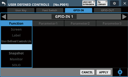
GPIO-IN page when setting controls
AFV indicators
If an item is selected as a trigger source for the Audio Follow Video function “AFV” will be shown here in blue.
Checking whether multiple functions have been assigned to an item is possible.
Functions are not assigned in the factory default settings.
NOTE
The GPIO input connector of a mounted SB-16D does not have functions assigned when shipped from the factory.
On this page, functions can be assigned to the GPIO output connector of this unit or of a mounted SB-16D connected through the built-in Dante.
See “Using GPIO extension functions” for details about using the GPIO connector of a mounted SB-16D.
Tap Menu Screen > Rear Panel Setup > GPIO Output Setup to open this page.
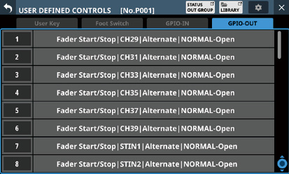
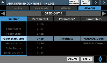
GPIO-OUT page when setting controls
The factory default settings are as follows.
|
Port number |
Assigned function |
|
1 |
Fader Start/Stop | CH29 | Alternate | NORMAL-Open |
|
2 |
Fader Start/Stop | CH31 | Alternate | NORMAL-Open |
|
3 |
Fader Start/Stop | CH33 | Alternate | NORMAL-Open |
|
4 |
Fader Start/Stop | CH35 | Alternate | NORMAL-Open |
|
5 |
Fader Start/Stop | CH37 | Alternate | NORMAL-Open |
|
6 |
Fader Start/Stop | CH39 | Alternate | NORMAL-Open |
|
7 |
Fader Start/Stop | STIN1 | Alternate | NORMAL-Open |
|
8 |
Fader Start/Stop | STIN2 | Alternate | NORMAL-Open |
NOTE
The GPIO output connector of a mounted SB-16D does not have functions assigned when shipped from the factory.
This sets the trigger level of the fader start/stop function (default: −60 dB).
1.Tap the ![]() button on the USER DEFINED CONTROLS Screen to open a settings window.
button on the USER DEFINED CONTROLS Screen to open a settings window.
2.Tap the setting level value of the Fader Start Level item in the window to change its appearance as shown below. The Channel Screens also switch to showing fader start setting.
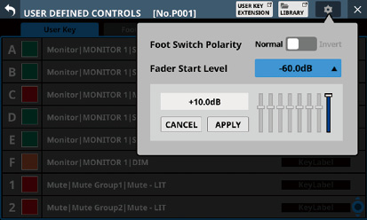
3.Adjust the channel faders on the right top panel to the desired start/stop trigger levels.
The adjusted values are shown in the window.

4.Tap the APPLY button to set the fader start level to the position of the corresponding fader, closing the window and returning to normal display.

Tap the CANCEL button to close the window and return to normal display.
On this screen, the extended USER KEY functions assigned on the USER DEFINED CONTROLS Screen can be shown and executed.
Use the following procedures to open this screen.
Tap Menu Screen > Mixer Setup > User Key Extension.
Tap the USER KEY EXTENSION button on the USER DEFINED CONTROLS Screen.
.jpg)
USER KEY SETUP button
Tap this button to open the USER DEFINED CONTROLS Screen.(See “USER DEFINED CONTROLS screen”.)
LIBRARY button
Tap this button to open the USER DEFINED CONTROLS LIBRARY Screen. (See “USER DEFINED CONTROLS LIBRARY Screen”.)
SIZE button
This sets the USER KEY display size.
The options for the number of items that can be shown at the same time are as follows.
Size S (32 items)
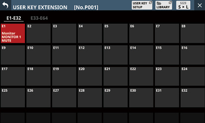
Size L (8 items)
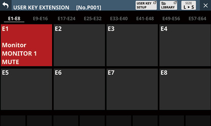
Page selection buttons
The selected page will be highlighted.
Extended USER KEY display
This shows the extended user keys and the functions assigned to them.
Tap an area shown to execute its function.
The content shown (including color and function) reflects the settings made on the USER DEFINED CONTROLS Screen.
If labels have been set for user keys, those labels will be shown on black bands.
Moreover, the brightness changes to show execution and other states in the same way as when functions are assigned to USER KEYS A–F and USER KEYS 1–12.
Example of appearance when MUTE function active
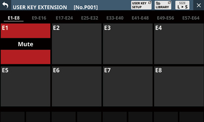
Example of appearance when MUTE function not active
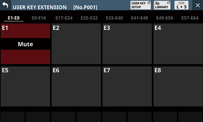
Use this screen to make group settings for the mute status and solo status of the GPIO-OUT port.
If the set group is selected with Parameter 1 when the Function setting is Mute Status or Solo Status on the GPIO-OUT page, the mute or solo status of that group will be output from the corresponding GPIO-OUT port.
Tap Menu Screen > Rear Panel Setup > GPIO Output Setup > STATUS OUT GROUP button to open this page.
Use this to select the modules assigned to GPIO-OUT Group 1-8, which are designated with Parameter 1 when the Function setting is Mute Status on the GPIO-OUT page.
.jpg)
.jpg)
GROUP buttons
These buttons select group numbers.
Selection pages
These are page buttons for selecting module types assigned to the selected group.
Buttons selected by tapping will be highlighted.
Module buttons
These are buttons for selecting modules assigned to the selected group.
The module label set for the Sub MODULE LABEL is shown at the left of the top line.
The module label set for the Main MODULE LABEL is shown in the bottom line. (See “DISPLAY MODE page”.)
Tapping these buttons to assign them to the group also highlights them.
NOTE
At the top right of each button, the Mute Group assignment status is shown and the DCA assignment status is shown in the bottom line in the same way as in the MODULE LABEL area on the Home Screen. (See “ MODULE LABEL area”.)
CLEAR ALL button
Tap this button to open a message confirming whether to clear all INPUT and OUTPUT/DAC/MUTE Grp assignments for the selected MUTE Assign group number.
![]()
Tap OK to clear all assignments.
Use this to select the modules assigned to GPIO-OUT Group 1-8, which are designated with Parameter 1 when the Function setting is Solo Status on the GPIO-OUT page.
.jpg)
.jpg)
GROUP buttons
These buttons select group numbers.
Selection pages
These are page buttons for selecting module types assigned to the selected group.
Buttons selected by tapping will be highlighted.
Module buttons
These are buttons for selecting modules assigned to the selected group.
The module label set for the Sub MODULE LABEL is shown at the left of the top line.
The module label set for the Main MODULE LABEL is shown in the bottom line. (See “DISPLAY MODE page”.)
Tapping these buttons to assign them to the group also highlights them.
NOTE
At the top right of each button, the Mute Group assignment status is shown and the DCA assignment status is shown in the bottom line in the same way as in the MODULE LABEL area on the Home Screen. (See “ MODULE LABEL area”.)
CLEAR ALL button
Tap this button to open a message confirming whether to clear all INPUT and OUTPUT/DAC assignments for the selected SOLO Assign group number. (See “DISPLAY MODE page”.)
![]()
Tap OK to clear all assignments.
Assign channel sets and custom layers to the 7 LAYER KEYS on this screen.
Tap Menu Screen > Front Panel Setup > Layer / Master Fader Setup to open this page.
.jpg)
Sonicview 24XP Layer Key SETUP Screen
.jpg)
Layer Key SETUP layer key setting screen
Page selection buttons
Tap these buttons to switch the page shown.
Layer Key names
The colors that LAYER KEYS 1–7 light when they are selected can be set.
Tap this area to open a color palette window.
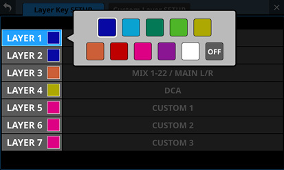
Tap a color in the color palette to change the layer key name button color and close the palette window.
Layer Key settings
This shows channel sets and custom layers assigned to LAYER KEYS 1–7.
Tap this area to open a settings screen for the layer keys.
![]() /
/![]() buttons
buttons
Tap these buttons to switch the LAYER KEYS (1–7) that is being edited.
Layer Key name
This shows the name of the currently selected LAYER KEYS (1–7).
![]() button
button
The colors that LAYER KEYS 1–7 light when they are selected can be set.
Tap this button to open a color palette window.
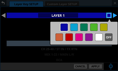
Tap a color in the color palette to change the layer key name display color and close the palette window.
Settings list
This shows channel sets and custom layers that can be set for LAYER KEYS 1–7.
To change a setting, swipe the list up and down. The setting can also be changed by turning LCD knob 8 (lit blue).
Settings that can be selected are as follows.
|
Model |
Option |
|
Sonicview 16XP |
CH 1-16 |
|
CH 17-32 |
|
|
CH 33-40 / ST IN / FX RTN |
|
|
MIX 1-16 |
|
|
MIX 17-22 / MAIN L/R |
|
|
DCA |
|
|
CUSTOM 1 |
|
|
CUSTOM 2 |
|
|
CUSTOM 3 |
|
|
CUSTOM 4 |
|
|
CUSTOM 5 |
|
|
CUSTOM 6 |
|
|
CUSTOM 7 |
|
|
Sonicview 24XP |
CH 1-24 |
|
CH 25-40 / ST IN / FX RTN |
|
|
MIX 1-22 / MAIN L/R |
|
|
DCA |
|
|
CUSTOM 1 |
|
|
CUSTOM 2 |
|
|
CUSTOM 3 |
|
|
CUSTOM 4 |
|
|
CUSTOM 5 |
|
|
CUSTOM 6 |
|
|
CUSTOM 7 |
CANCEL button
Tap this button to cancel setting changes and close to the layer settings screen.
APPLY button
Tap this button to confirm setting changes and close to the layer settings screen.
Scroll knob icon
This icon shows that LCD knob 8 (lit light blue) can be used to scroll.
Default settings for LAYER KEYS 1–7
The factory default settings are as follows.
Sonicview 16XP
|
Key |
Lit color |
Assigned function |
|
LAYER 1 |
Blue |
CH 1-16 |
|
LAYER 2 |
Blue |
CH 17-32 |
|
LAYER 3 |
Blue |
CH 33-40 / ST IN / FX RTN |
|
LAYER 4 |
Orange |
MIX 1-16 |
|
LAYER 5 |
Orange |
MIX 17-22 / MAIN L/R |
|
LAYER 6 |
Yellow |
DCA |
|
LAYER 7 |
Pink |
CUSTOM 1 |
Sonicview 24XP
|
Key |
Lit color |
Assigned function |
|
LAYER 1 |
Blue |
CH 1-24 |
|
LAYER 2 |
Blue |
CH 25-40 / ST IN / FX RTN |
|
LAYER 3 |
Orange |
MIX 1-22 / MAIN L/R |
|
LAYER 4 |
Yellow |
DCA |
|
LAYER 5 |
Pink |
CUSTOM 1 |
|
LAYER 6 |
Pink |
CUSTOM 2 |
|
LAYER 7 |
Pink |
CUSTOM 3 |
The modules assigned to custom layers and the modules assigned to the master fader can be set in the settings list on this screen.
Tap Menu Screen > Front Panel Setup > Layer / Master Fader Setup to open the Layer Key SETUP page. Then, tap the Custom Layer SETUP button to open this page.
.jpg)
Page selection buttons
Tap these buttons to switch the page shown.
Custom Layer selection
This shows the name of the custom layer that is being edited.
Tap this area to open a window where the custom layer can be selected.
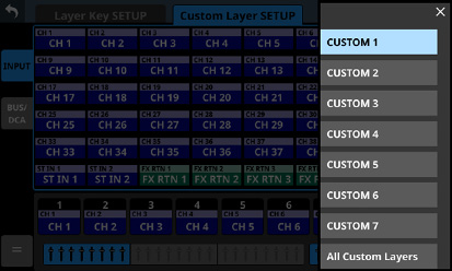
Tap the name of the custom layer to be edited to close this window and show the module labels for the display mode set by the Sub MODULE LABEL or Main MODULE LABEL (See “DISPLAY MODE page”.) for the modules assigned to the selected custom layer in the custom layer slot buttons ().
Tap “All Custom Layers” in the window to close the window and open the All Custom Layers display.
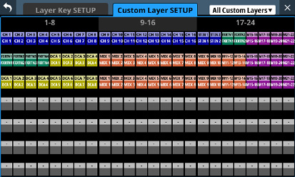
This shows the module labels for the display mode set by the Sub MODULE LABEL or Main MODULE LABEL (See “DISPLAY MODE page”.) for the modules assigned to all 7 custom layers on one line per layer.
Tap a button shown to switch to display of its custom layer.
Module group switching buttons
Tap these buttons to change which group of modules assigned to the layer is shown.
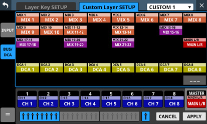
Module buttons
These are the buttons for the modules in the group assigned to the layer.
Use the module group switching buttons to select the shown group.
Custom layer slot buttons
In sets of 8 channels, these show the module labels for the display mode set by the Sub MODULE LABEL or Main MODULE LABEL (See “DISPLAY MODE page”.) of the modules assigned to the custom layer that is being edited. Modules that are not assigned will appear blank (![]() ).
).
Use the block selection buttons () to switch the 8 channels that are shown.
![]() button
button
Tap this button to open the custom layer editing menu.
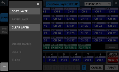
Items that can be used will be shown highlighted.
|
Menu item |
Function |
|
COPY LAYER |
This copies the setting state of the selected custom layer to a buffer. |
|
PASTE LAYER |
This pastes the custom layer setting state copied to the buffer to the selected custom layer. |
|
CLEAR LAYER |
This clears all the settings of the selected custom layer. A confirmation message will appear before clearing is executed. |
|
INSERT BLANK |
This inserts a blank at the position of the selected slot button (framed in yellow). When this is done, the contents assigned to the selected slot button and the slot buttons to its right will be shifted right. |
|
DELETE |
This deletes the assignment of the selected slot button (framed in yellow) and shifts left by one slot the settings to its right. Doing this causes the rightmost slot button to become blank. |
|
CLEAR |
This removes the assignment of the selected slot button (framed in yellow). This does not move any slot buttons. |
Block selection buttons
The block selection button for the 8 channels that are shown is highlighted.
Tap one of these buttons to switch the shown 8-channel block, which shows custom layer and slot buttons ().
CANCEL button
Tap this button to cancel setting changes.
APPLY button
Tap this button to confirm setting changes.
![]() button
button
Tap this button to make the assignment of the selected slot (framed in yellow) blank.
MASTER slot button
This shows the module label for the display mode set by the Sub MODULE LABEL or Main MODULE LABEL of the module assigned to the MASTER fader (MAIN L/R by default), which does not depend on layer selection. (See “DISPLAY MODE page”.)
Custom layer assignment operation procedures
Selecting the custom layer slot button followed by the module button
1.Tap the custom layer slot button to select it for assignment change.
Selecting will make a yellow frame appear.
.jpg)
2.Tap the button for the module to be assigned to the selected slot.
This will assign the tapped module to the custom layer slot selected in step 1.
.jpg)
3.Tap the APPLY button to confirm setting changes.
Tap the CANCEL button to cancel setting changes.
Selecting the module button followed by the custom layer slot button
1.Tap the button for the module to be assigned.
Selecting will make a yellow frame appear.
.jpg)
2.Tap the button for the custom layer slot to assign the selected module to it.
This will assign the module selected in step 1 to the tapped custom layer slot.
.jpg)
3.Tap the APPLY button to confirm setting changes.
Tap the CANCEL button to cancel setting changes.
NOTE
In either procedure, multiple buttons can be selected in step 1 and assigned consecutively at one time.
Make talkback settings on the TALKBACK page of the TALKBACK / MONITOR / SOLO / OSC SETUP screen.
Tap Menu Screen > Mixer Setup > Talkback / Monitor / Solo / OSC to open this screen.
.jpg)
Page appearance when the input source for the TALKBACK signal is “TALKBACK IN”
NOTE
This screen can also be opened by pressing the TALKBACK key while pressing the MENU key. (See “16 - List of shortcut operations”.)
Using the User Defined Control function, this screen can also be opened with a USER KEYS, footswitch or the GPIO-IN. (See “USER DEFINED CONTROLS screen”.)
Each level meter has an overload indicator at its top.
INPUT SEL button
This shows the name of the input source for the TALKBACK signal.
The upper line shows an abbreviation of the FIXED PORT LABEL.
The lower line shows the USER PORT LABEL.
If the USER PORT LABEL is undefined, the FIXED PORT LABEL will be shown.
Tap this button to open the TALKBACK INPUT SELECT Screen where the input port for the TALKBACK signal can be selected.
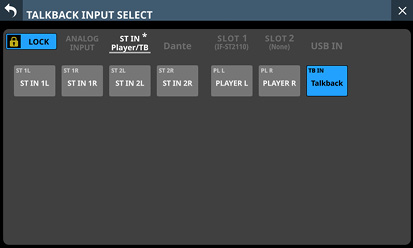
This screen shows the same content as the INPUT SOURCE SELECT Screen and is operated in the same way, except for being able to select “TALKBACK IN” on the ST IN and Player/TB page.
See “INPUT SOURCE SELECT screen” for details.
LOCATION setting button
This shows the Location setting of the TALKBACK mic.
Tap this area to open the Location setting menu.
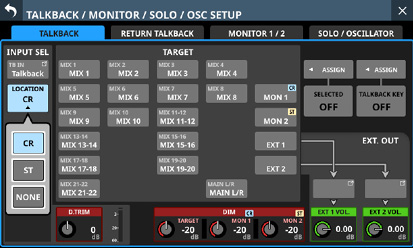
|
Button |
Meaning |
|
CR (default) |
This sets the Location of the TALKBACK mic to Control Room (CR). |
|
ST |
This sets the Location of the TALKBACK mic to Studio (ST). |
|
NONE |
This leaves the Location of the TALKBACK mic unset. |
+48V button
Use this button to supply phantom power to the input source of the TALKBACK signal.
Press and hold the +48V button to turn phantom power (+48V) on/off. (Default: OFF)
When this is on, the button will appear highlighted.
This only appears when the input shown by the INPUT SEL button is “ANALOG”, “SB-16D connected by built-in Dante” or “TALKBACK IN”.
A black button that cannot be operated will be shown if the input source for the TALKBACK signal is an SB-16D for which control privileges are not held.
PAD button
The PAD button is shown when the input source of the TALKBACK signal is “ANALOG” or “SB-16D connected by built-in Dante”.
Tap this button to turn the −20 dB pad on/off. (Default: off)
When this button is on, it will appear highlighted.
A black button that cannot be operated will be shown if the input source for the TALKBACK signal is an SB-16D for which control privileges are not held.
Analog GAIN knob
When the input source of the TALKBACK signal is “ANALOG” or “SB-16D connected by built-in Dante”, an analog gain knob will be shown for this unit or the SB-16D. This knob can be used to adjust the input level of the MIC/LINE input jack.
Turn LCD knob 1 (lit red) to adjust it.
A black knob that cannot be operated will be shown if the input source for the TALKBACK signal is an SB-16D for which control privileges are not held.
NOTE
Use the TALKBACK volume knob on the top panel to adjust the TALKBACK IN analog input level. (See “ TALKBACK volume”.)
D.TRIM knob
Use this to adjust the TALKBACK signal digital trim value.
Range: −20 dB – +20 dB (default: 0 dB)
Turn LCD knob 2 (lit red) to adjust it.
TALKBACK level meter
This shows the TALKBACK signal input level.
When TALKBACK is on, this adjusts the attenuation of the TARGET signal that is being interrupted by the TALKBACK signal.
Range: −40 dB – 0 dB (default: −20 dB)
Turn LCD knob 4 (lit red) to adjust it.
When any TARGET button is on and dimming is applied to the TARGET signal in the amount set by the DIM TARGET knob, “DIM” will appear in orange in this area.
NOTE
This setting is shared with the RETURN TALKBACK page (“ DIM TARGET knob”).
When TALKBACK is on, use these to adjust the attenuation of MONITOR 1 and MONITOR 2.
Range: −40 dB – 0 dB (default: −20 dB)
Use LCD knobs 5–6 (lit red) to adjust these.
When TALKBACK is on and dimming is applied to MON 1 in the amount set by the DIM MON 1 knob, “DIM” will appear in orange in the DIM MON 1 area.
When TALKBACK is on and dimming is applied to MON 2 in the amount set by the DIM MON 2 knob, “DIM” will appear in orange in the DIM MON 2 area.
If the Location setting for MONITOR 1 or MONITOR 2 is “CR” or “ST”, “CR” or “ST” will appear to the top right of the DIM MON 1/2 knob area.
NOTE
This setting is shared with the RETURN TALKBACK page (“ DIM MON 1 and MON 2 knobs”).
Tap bus module buttons to set the buses that will be interrupted with the TALKBACK signal. (These are off by default.)
Buttons for selected talkback destinations will be highlighted.
Tapping the MON 1/MON 2 button will output the TALKBACK signal to MONITOR 1/MONITOR 2.
If the Location setting for MONITOR 1 or MONITOR 2 is “CR” or “ST”, “CR” or “ST” will be shown on the MON 1/2 button.
Tapping the EXT 1 button will output the TALKBACK signal to the output port assigned to the EXT 1 OUT button.
Tapping the EXT 2 button will output the TALKBACK signal to the output port assigned to the EXT 2 OUT button.
NOTE
The bus module buttons show module labels according to the display modes set for the Sub MODULE LABEL in the upper line and the Main MODULE LABEL in the lower line. (See “DISPLAY MODE page”.)
Stereo buses have a single button for each pair.
Tap this button to turn it on and off. Press and hold this button to turn the function on only while being pressed.
SELECTED ASSIGN button
Tap this button to open a window where you can select the output destinations for which you want to enable TALKBACK output when the SELECTED button is pressed.
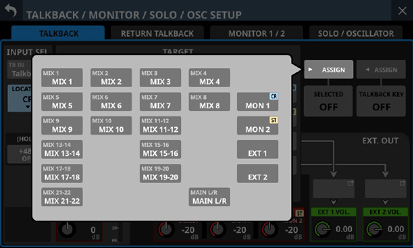
Tap an option to select that output for the TALKBACK signal. (These are off by default.)
Buttons for selected outputs will be highlighted.
If the Location setting for MONITOR 1 or MONITOR 2 is “CR” or “ST”, “CR” or “ST” will be shown on the MON 1/2 button.
Tap this button when the selection window is open to confirm the setting and close the window.
NOTE
Stereo buses have a single button for each pair.
SELECTED button
Tap this button to turn on/off the TALKBACK function for output destinations selected on the window shown using the SELECTED ASSIGN button.
When this button is on, set buttons will appear highlighted.
NOTE
Tap this button to turn it on and off. Press and hold this button to turn the function on only while being pressed.
TALKBACK KEY ASSIGN button
Tap this button to open a window where you can select the output destinations for which you want to enable TALKBACK output when the TALKBACK key on the top panel or the TALKBACK KEY button is pressed.
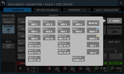
Tap an option to select that output destination. (These are off by default.)
Buttons for selected outputs will be highlighted.
If the Location setting for MONITOR 1 or MONITOR 2 is “CR” or “ST”, “CR” or “ST” will be shown on the MON 1/2 button.
Tap this button when the selection window is open to confirm the setting and close the window.
TALKBACK KEY button
Tap this button to turn on/off the TALKBACK function for output destinations selected on the window shown using the TALKBACK KEY ASSIGN button (off by default).
When this is ON, the button will appear highlighted.
NOTE
This has the same function as the TALKBACK key on the top panel.
Tap this button to switch it ON and OFF. Press and hold this button to turn the function on only while being pressed.
Using the User Defined Control function, TALKBACK ON/OFF switching is also possible with a USER KEYS, the footswitch or the GPIO-IN. (See “USER DEFINED CONTROLS screen”.)
These show the names of the output ports assigned to the EXT 1 OUT and EXT 2 OUT buttons.
The upper line shows an abbreviation of the FIXED PORT LABEL.
The lower line shows the USER PORT LABEL.
If the USER PORT LABEL is undefined, the FIXED PORT LABEL will be shown.
Tap these buttons to open the TALKBACK EXT1 DIRECT OUT PORT SELECT and TALKBACK EXT2 DIRECT OUT PORT SELECT screens where output ports for the TALKBACK signal can be selected.
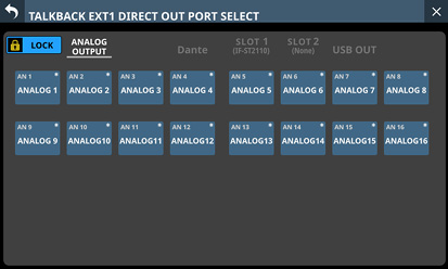
TALKBACK EXT1 DIRECT OUT PORT SELECT Screen
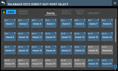
TALKBACK EXT2 DIRECT OUT PORT SELECT Screen
These screens show the same content as the OUTPUT PORT SELECT Screen and are operated in the same way.
See “OUTPUT PORT SELECT screen” for details.
EXT 1 VOL. / EXT 2 VOL. knobs
These adjust the output levels of the TALKBACK signals sent to the output ports assigned to the EXT 1 and EXT 2 buttons.
Range: −∞ dB – +10 dB (default: 0 dB)
Turn LCD knobs 7 and 8 (lit green) to adjust them.
Make return talkback settings on the RETURN TALKBACK page of the TALKBACK / MONITOR / SOLO / OSC SETUP screen.
Tap Menu Screen > Mixer Setup > Talkback / Monitor / Solo / OSC to open this screen.
.jpg)
Page appearance when the input source for the TALKBACK signal is “ANALOG 1”
INPUT SEL button
This shows the name of the input source for the RETURN TALKBACK signal.
The upper line shows an abbreviation of the FIXED PORT LABEL.
The lower line shows the USER PORT LABEL.
If the USER PORT LABEL is undefined, the FIXED PORT LABEL will be shown.
Tap this button to open the RETURN TALKBACK INPUT SELECT Screen where the input port for the RETURN TALKBACK signal can be selected.
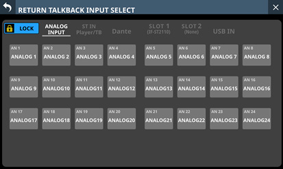
This screen shows the same content as the INPUT SOURCE SELECT Screen and is operated in the same way, except for being able to select “TALKBACK IN” on the ST IN and Player/TB page.
See “INPUT SOURCE SELECT screen” for details.
LOCATION setting button
This shows the location setting of the RETURN TALKBACK mic.
Tap this area to open the location setting menu.
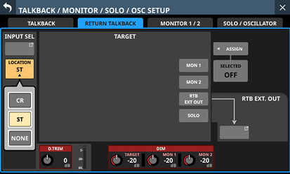
|
Button |
Meaning |
|
CR |
This sets the location of the RETURN TALKBACK mic to Control Room (CR). |
|
ST (default) |
This sets the location of the RETURN TALKBACK mic to Studio (ST). |
|
NONE |
This leaves the location of the RETURN TALKBACK mic unset. |
+48V button
Use this button to supply phantom power to the input source of the RETURN TALKBACK signal.
Press and hold the +48V button to turn phantom power (+48V) on/off. (Default: OFF)
When this is on, the button will appear highlighted.
This only appears when the input shown by the INPUT SEL button is “ANALOG”, “SB-16D connected by built-in Dante” or “TALKBACK IN”.
A black button that cannot be operated will be shown if the input source for the RETURN TALKBACK signal is an SB-16D for which control privileges are not held.
PAD button
The PAD button is shown when the input source of the RETURN TALKBACK signal is “ANALOG” or “SB-16D connected by built-in Dante”.
Tap this button to turn the −20dB pad on/off. (Default: off)
When this button is on, it will appear highlighted.
A black button that cannot be operated will be shown if the input source for the RETURN TALKBACK signal is an SB-16D for which control privileges are not held.
Analog GAIN knob
When the input source of the RETURN TALKBACK signal is “ANALOG” or “SB-16D connected by built-in Dante”, an Analog GAIN knob will be shown for this unit or the SB-16D. This knob can be used to adjust the input level of the MIC/LINE input jack.
Turn LCD knob 1 (lit red) to adjust it.
A black knob that cannot be operated will be shown if the input source for the RETURN TALKBACK signal is an SB-16D for which control privileges are not held.
NOTE
Use the TALKBACK volume knob on the top panel to adjust the TALKBACK IN analog input level. (See “ TALKBACK volume”.)
D.TRIM knob
Use this to adjust the RETURN TALKBACK signal digital trim value.
Range: −20 dB – +20 dB (default: 0 dB)
Turn LCD knob 2 (lit red) to adjust it.
TALKBACK level meter
This shows the RETURN TALKBACK signal input level.
When TALKBACK is on, this adjusts the attenuation of the TARGET signal that is being interrupted by the TALKBACK signal.
Range: −40 dB – 0 dB (default: −20 dB)
Turn LCD knob 5 (lit red) to adjust it.
When any TARGET button is on and dimming is applied to the TARGET signal in the amount set by the DIM TARGET knob, an orange DIM button will appear in this area.
NOTE
This setting is shared with the TALKBACK page (“ DIM TARGET knob”).
When TALKBACK is on, use these to adjust the attenuation of MONITOR 1 and MONITOR 2.
Range: −40 dB – 0 dB (default: −20 dB)
Turn LCD knobs 5 and 6 (lit red) to adjust them.
When TALKBACK is on and dimming is applied to MON 1 in the amount set by the DIM MON 1 knob, an orange DIM button will appear in the DIM MON 1 area.
When TALKBACK is on and dimming is applied to MON 2 in the amount set by the DIM MON 2 knob, an orange DIM button will appear in the DIM MON 2 area.
If the Location setting for MONITOR 1 or MONITOR 2 is “CR” or “ST”, “CR” or “ST” will appear to the top right of the DIM MON 1/2 knob area.
NOTE
This setting is shared with the TALKBACK page (“ DIM MON 1 and MON 2 knobs”).
TARGET buttons
Tap these buttons to select them for interruption by RETURN TALKBACK signals. (Default: off)
Buttons for selected talkback destinations will be highlighted.
Tapping the MON 1/MON 2 button will output the RETURN TALKBACK signal to MONITOR 1/MONITOR 2.
If the LOCATION setting for MONITOR 1 or MONITOR 2 is “CR” or “ST”, “CR” or “ST” will be shown on the MON 1/2 buttons.
Tapping the EXT OUT button will output the RETURN TALKBACK signal to the output port assigned to the RTB EXT OUT button.
Tapping the SOLO button will output the RETURN TALKBACK signal to SOLO bus.
NOTE
Tap this button to turn it on and off. Press and hold this button to turn the function on only while being pressed.
SELECTED ASSIGN button
Tap this button to open a window where you can select the output destinations for which you want to enable RETURN TALKBACK output when the SELECTED button is pressed.
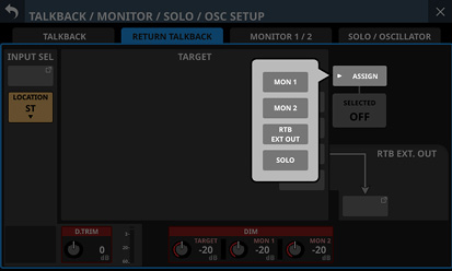
Tap an option to select that output for the RETURN TALKBACK signal. (Default: off)
Buttons for selected outputs will be highlighted.
If the Location setting for MONITOR 1 or MONITOR 2 is “CR” or “ST”, “CR” or “ST” will be shown on the MON 1/2 button.
Tap this button when the selection window is open to confirm the setting and close the window.
SELECTED button
Tap this button to turn on/off RETURN TALKBACK for output destinations selected on the window shown using the SELECTED ASSIGN button.
When this button is on, set buttons will appear highlighted.
NOTE
Tap this button to turn it on and off. Press and hold this button to turn the function on only while being pressed.
RTB EXT. OUT button
This shows the names of the output ports that the RETURN TALKBACK signal is assigned to.
The upper line shows an abbreviation of the FIXED PORT LABEL.
The lower line shows the USER PORT LABEL.
If the USER PORT LABEL is undefined, the FIXED PORT LABEL will be shown.
Tap this button to open the Return TALKBACK EXT DIRECT OUT PORT SELECT Screen where output ports for the RETURN TALKBACK signal can be selected.
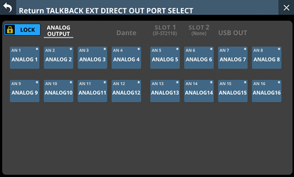
This screen shows the same content as the OUTPUT PORT SELECT Screen and is operated in the same way.
See “OUTPUT PORT SELECT screen” for details.
Making monitor output settings
Make monitor output settings on the MONITOR 1/2 pages of the TALKBACK / MONITOR / SOLO / OSC SETUP screen.
Tap Menu Screen > Mixer Setup > Talkback / Monitor / Solo / OSC to open this screen.
.jpg)
SEL button
This button can be used to switch between MONITOR 1 and MONITOR 2, which could be large and small monitors.
When the Monitor Exclusive button on the Additional Settings page (Additional settings window) is on, this button will be highlighted and can be used, and  or
or  will appear.
In this state, tap this button to select output exclusively from MONITOR 1 or MONITOR 2. and will appear alternately to the left and right of the button.
|
MONITOR 1 MUTE button |
MONITOR 2 MUTE button |
|
|
When |
Off |
On |
|
When |
On |
Off |
When the Monitor Exclusive button is off, this button will appear gray and cannot be used, and or will not be shown.
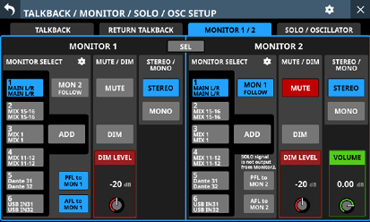
![]() icon
icon
Tap this icon to open the Additional settings window. (See “Additional settings window”.)
Tap this button to turn monitoring signal muting on and off (default).
When this is on, the button will appear highlighted.
NOTE
Output from the headphone jacks will not be muted.
When MONITOR 1 is muted because of the Monitor Exclusive or Location function, muting cannot be disabled by tapping this button.
Using the User Defined Control function, monitor muting can also be operated with a USER KEYS, the footswitch or the GPIO-IN. (See “USER DEFINED CONTROLS screen”.)
The following USER KEY is set for MONITOR 1 on the User Key page by default.
USER KEYS C (Monitor | MONITOR 1 | MUTE)
![]() icon (MONITOR 1)
icon (MONITOR 1)
Tap this icon to open the MONITOR 1 SOURCE ASSIGN Screen. (See “MONITOR SOURCE ASSIGN screen”.)
Tap this button to turn on/off the function that has MONITOR 1 monitor the signal of MONITOR 2. (This is off by default.)
When this is on, the button will appear highlighted.
MONITOR SELECT buttons (MONITOR 1)
These show the names of the monitoring sources selected on the MONITOR SOURCE ASSIGN Screen. (See “MONITOR SOURCE ASSIGN screen”.)
These buttons show the names of the monitoring sources with the L channels in the upper lines and the R channels in the lower lines.
If the selected monitoring source is a bus module, the USER MODULE LABEL will be shown. (See “DISPLAY MODE page”.)
If the USER MODULE LABEL is undefined, the FIXED MODULE LABEL will be shown.
If a selected monitoring source is an Input jack, the PORT LABEL selected with the PORT LABEL display mode setting will be shown. (See “DISPLAY MODE page”.)
If a Dante port that has a mounted SB-16D assigned is selected as a monitoring source, “SB #[ID] [port number]” will be shown at the top of the button. If it is a virtually-mounted SB-16D, ![]() will appear to the right of the monitoring source name.
will appear to the right of the monitoring source name.
![]()
Tap these buttons to select monitoring sources output from the following connectors.
Front panel headphone jacks
Rear panel MONITOR OUT L/R jacks
MONITOR 1 Direct OUT PORT (See “ Direct OUT PORT button (MONITOR 1)”.)
Tapping these buttons when the MONITOR 1 ADD button is off will select only one monitor source. The selected button will be highlighted light blue.
Multiple monitor sources can be selected by tapping these buttons when the MONITOR 1 ADD button is on. This allows multiple selected monitoring sources to be mixed and monitored together. The selected button will be highlighted yellowish green.
If the MONITOR SELECT button for a Dante port that has a virtually mounted SB-16D assigned is selected, the selected button will be highlighted yellow.
![]()
NOTE
If a bus is selected as the monitoring source, sound output from the unit will be monitored. Monitoring will also be silent if the Metering Point setting is “OUTPUT” for the selected bus but no assignment has been made to an output port (no external output from the unit). To monitor a bus AFL, use the SOLO function.
Using the User Defined Control function, MONITOR SELECT 1–6 can also be operated with USER KEYS, the footswitch or the GPIO-IN. (See “USER DEFINED CONTROLS screen”.)
The following USER KEYS are set for MONITOR SELECT 1–4 on the User Key page by default.
USER KEYS A (Monitor | MONITOR 1 | Source select | 1 (MAIN L/R))
USER KEYS B (Monitor | MONITOR 1 | Source select | 2 (MIX 15-16))
USER KEYS D (Monitor | MONITOR 1 | Source select | 3 (MIX 1))
USER KEYS E (Monitor | MONITOR 1 | Source select | 4 (MIX 11-12))
Tap this button to turn on/off the ADD function, which enables selecting multiple monitoring sources at the same time, for MONITOR 1 (off by default).
When this is on, the button will appear highlighted.
PFL to MON 1/AFL to MON 1 buttons
Tap these buttons to set whether or not to switch the MONITOR 1 monitoring signal to the SOLO signal (on by default).
When this is on, the button will appear highlighted.
|
Button |
Function |
|
|
If SOLO is turned on when SOLO TYPE is “PFL”, the MONITOR 1 monitoring signal will switch to the SOLO signal. |
|
|
If SOLO is turned on when SOLO TYPE is “AFL”, the MONITOR 1 monitoring signal will switch to the SOLO signal. |
NOTE
If both buttons are turned off, the SOLO signal will stop being output from MONITOR 1 even if the SOLO key is pressed. For this reason, “SOLO signal is not output from Monitor 1” will be shown as a warning in the area above the PFL to MON 1 button.
![]()
DIM LEVEL knob (MONITOR 1)
This adjusts the attenuation of the monitoring signal when the MONITOR 1 DIM function is on.
Range: −40 dB – 0 dB (default: −20 dB)
Turn LCD knob 3 (lit red) to adjust it.
Tap this button to turn the monitoring dimming function on and off (default).
When the MONITOR 1 DIM function is on, the monitoring signal output level will be lowered according to the DIM LEVEL () setting.
When this is on, the button will appear highlighted.
NOTE
This button affects the output signals of MONITOR OUT L/R and headphone jacks.
Tap this button to turn it on and off. Press and hold this button to turn the function on only while being pressed.
Using the User Defined Control function, the MONITOR 1 DIM function can also be operated with a USER KEY, the footswitch or the GPIO-IN. (See “USER DEFINED CONTROLS screen”.)
The following USER KEY is set for the MONITOR 1 DIM function on the User Key page by default.
USER KEYS F (Monitor | MONITOR 1 | DIM)
STEREO/MONO buttons (MONITOR 1)
Tap these buttons to switch between MONO and STEREO (default) for monitoring signals.
The selected button will be highlighted.
MONITOR SELECT buttons (MONITOR 2)
These show the names of the monitoring sources selected on the MONITOR 2 SOURCE ASSIGN Screen. (See “MONITOR SOURCE ASSIGN screen”.)
Tap these buttons to select monitoring sources output from the following connectors.
MONITOR 2 Direct OUT PORT (See “ Direct OUT PORT button (MONITOR 2)”.)
MONITOR 2 OUTPUT PORT (See “ OUTPUT PORT button (MONITOR 2)”.)
Tapping these buttons when the MONITOR 2 ADD button is off will select only one monitor source. The selected button will be highlighted light blue.
Multiple monitor sources can be selected by tapping these buttons when the MONITOR 2 ADD button is on. This allows multiple selected monitoring sources to be mixed and monitored together. The selected button will be highlighted yellowish green.
These have the same function as the MONITOR SELECT () button for MONITOR 1.
Tap this button to turn on/off the ADD function, which enables selecting multiple monitoring sources at the same time, for MONITOR 2 (off by default).
When this is on, the button will appear highlighted.
PFL to MON 2/AFL to MON 2 buttons
Tap these buttons to set whether or not to switch the MONITOR 2 monitoring signal to the SOLO signal (off by default).
When this is on, the button will appear highlighted.
|
Button |
Function |
|
|
If SOLO is turned on when SOLO TYPE is “PFL”, the MONITOR 2 monitoring signal will switch to the SOLO signal. |
|
|
If SOLO is turned on when SOLO TYPE is “AFL”, the MONITOR 2 monitoring signal will switch to the SOLO signal. |
NOTE
If both buttons are turned off, the SOLO signal will stop being output from MONITOR 2 even if the SOLO key is pressed. For this reason, “SOLO signal is not output from Monitor 2” will be shown as a warning in the area above the PFL to MON 2 button.
![]()
DIM LEVEL knob (MONITOR 2)
This adjusts the attenuation of the monitoring signal when the MONITOR 2 DIM function is on.
Range: −40 dB – 0 dB (default: −20 dB)
Turn LCD knob 7 (lit red) to adjust it.
Tap this button to turn the monitoring dimming function on and off (default).
When the MONITOR 2 DIM function is on, the monitoring signal output level will be lowered according to the DIM LEVEL () setting.
When this is on, the button will appear highlighted.
NOTE
Tap this button to turn it on and off. Press and hold this button to turn the function on only while being touched.
Using the User Defined Control function, the MONITOR 2 DIM function can also be operated with a USER KEY, the footswitch or the GPIO-IN. (See “USER DEFINED CONTROLS screen”.)
VOLUME knob (MONITOR 2)
Use this to adjust the MONITOR 2 output level.
Range: −∞ dB – +10 dB (default: 0 dB)
Turn LCD knob 8 (lit green) to adjust it.
Tap this button to turn on/off the function that has MONITOR 2 monitor the signal of MONITOR 1 (on by default).
When this is on, the button will appear highlighted.
![]() icon (MONITOR 2)
icon (MONITOR 2)
Tap this icon to open the MONITOR 2 SOURCE ASSIGN Screen. (See “MONITOR SOURCE ASSIGN screen”.)
Tap this button to turn monitoring signal muting on and off (on by default).
When this is on, the button will appear highlighted.
NOTE
When MONITOR 2 is muted because of the Monitor Exclusive or Location function, muting cannot be disabled by tapping this button.
Using the User Defined Control function, MONITOR 2 muting can also be done with a USER KEY, the footswitch or the GPIO-IN. (See “USER DEFINED CONTROLS screen”.)
STEREO/MONO buttons (MONITOR 2)
Tap these buttons to switch between MONO and STEREO (default) for monitoring signals.
The selected button will be highlighted.
On this screen, assign monitoring sources for monitoring from the front panel headphone jacks and the rear panel MONITOR OUT L/R jacks to the 6 MONITOR SELECT buttons.
To open this screen, tap the ![]() icon in the MONITOR SELECT area on the right side of the MONITOR SELECT button of the TALKBACK / MONITOR / SOLO / OSC SETUP Screen.
icon in the MONITOR SELECT area on the right side of the MONITOR SELECT button of the TALKBACK / MONITOR / SOLO / OSC SETUP Screen.
.jpg)
MONITOR 1 SOURCE ASSIGN screen
L/R selection buttons
These select which output ports of the monitoring source left/right channels to set.
Tap these buttons to switch between left and right. The selected button will be highlighted.
MONITOR SELECT page switches
Monitoring sources can be assigned on each MONITOR SELECT page separately.
The names of the assigned monitoring sources are shown on the MONITOR SELECT page.
These buttons show the names of the monitoring sources with the L channels in the upper lines and the R channels in the lower lines. If the selected monitoring source is a bus module, the USER MODULE LABEL will be shown. (See “MODULE LABEL page”.)
If the USER MODULE LABEL is undefined, the FIXED MODULE LABEL will be shown.
If a selected monitoring source is an Input jack, the PORT LABEL selected with the PORT LABEL display mode setting will be shown. (See “DISPLAY MODE page”.)
Tap this area to switch open MONITOR SELECT pages.
Monitoring source group page switches
These show monitor source group page names.
Tap a page name to switch to the page with the corresponding monitoring sources.
The name of the selected page will be highlighted.
|
Page name |
Contents |
|
MIX MAIN L/R |
Select output signals from MIX 1–22 and MAIN L/R Master modules. |
|
MON SOLO |
Select other monitoring signals and SOLO bus signals. |
|
ANALOG INPUT |
Select input signals from analog MIC/LINE input jacks. |
|
ST-IN PLAYER |
Select input signals from the two pairs of ST IN jacks and the internal player. |
|
Dante |
Select input signals from the Dante connectors. |
|
SLOT 1 |
Select the inputs of the expansion card installed in SLOT 1. |
|
SLOT 2 |
Select the inputs of the expansion card installed in SLOT 2. |
|
USB IN |
Select USB audio interface inputs. |
Monitoring source assignment buttons
Tap these buttons to select monitor sources to assign to the selected MONITOR SELECT button. Assigned buttons will be highlighted light blue. Assigned buttons for Dante ports that have virtually-mounted SB-16Ds will be highlighted yellow.
The bus module buttons show the FIXED MODULE LABEL in the upper line and the USER MODULE LABEL in the lower line. (See “MODULE LABEL page”.)
If the USER MODULE LABEL is undefined, the FIXED MODULE LABEL will be shown.
The input jack buttons show an abbreviated FIXED PORT LABEL in the upper line and a USER PORT LABEL in the lower line. (See “INPUT PORT LABEL page” and “OUTPUT PORT LABEL page”)
If the USER PORT LABEL is undefined, the FIXED PORT LABEL will be shown.
Buttons for Dante ports that have mounted SB-16Ds assigned will be shown as follows.
1st line: DA port number
2nd line: SB #[ID] port number
3rd line: USER PORT LABEL or SB #[ID] port number (if the USER PORT LABEL is undefined)
If it is a virtually-mounted SB-16D, ![]() will appear to the top right.
will appear to the top right.
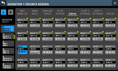
.jpg)
Tap this button to turn on/off the Monitor Exclusive function that selects exclusively the output of MONITOR 1 or MONITOR 2. Use this function to switch between MONITOR 1 and MONITOR 2, which could be large and small monitors (on by default).
When on, this button is highlighted and the MONITOR 1/2 page SEL button is enabled.
NOTE
If the Location of any monitors are set to “ST” (See “ Monitor Location setting area”.), the Monitor Exclusive button cannot be switched on and the MONITOR 1/2 exclusive function cannot be used.
To use the MONITOR 1/2 exclusive function, set the monitor Location to “CR” or “NONE”.
DELAY button
Tap this button to turn the delay function ON and OFF (default). This can be used to adjust the timing of the monitoring signal, for example.
When this is ON, the button will appear highlighted.
DELAY TIME
This adjusts the delay time used to correct the timing of monitoring signals, for example.
The highlighted unit will be used for operation, so tap the button for the desired unit.
|
Unit options |
Range |
|
meter |
0 – 117.3 (meter) |
|
feet |
0 – 384.8 (feet) |
|
msec (default) |
0 – 341.32 (msec) |
Turn LCD knob 2 (lit green) to adjust it.
LOCATION setting buttons (MONITOR 1)
Tap these buttons to change the Location setting of MONITOR 1. (The default setting is NONE.)
See “ Monitor Location setting area” for details about Location settings.
When the MONITOR 1 Location is set, “CR” or “ST” icons will be shown on the additional settings window and to the right of the MONITOR 1 display on the MONITOR 1/2 page.
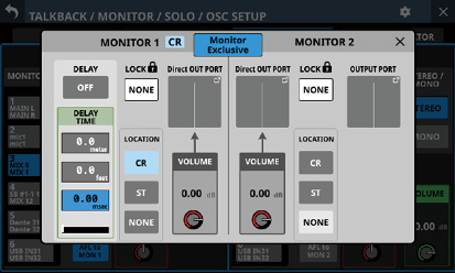
Appearance when MONITOR 1 Location set to “CR”
Direct OUT PORT VOLUME knob (MONITOR 1)
Use this to adjust the output level from the MONITOR 1 DIRECT OUT PORT.
Range: −∞ dB – +10 dB (default: 0 dB)
Turn LCD knob 4 (lit red) to adjust it.
Direct OUT PORT button (MONITOR 1)
This shows the name of the output port that the MONITOR 1 DIRECT OUT signal is assigned to.
The upper line shows an abbreviation of the FIXED PORT LABEL.
The lower line shows the USER PORT LABEL. If the USER PORT LABEL is undefined, the FIXED PORT LABEL will be shown.
Tap this button to open the MONITOR 1 DIRECT OUT PORT SELECT Screen where DIRECT OUT signal output ports for MONITOR 1 can be selected.
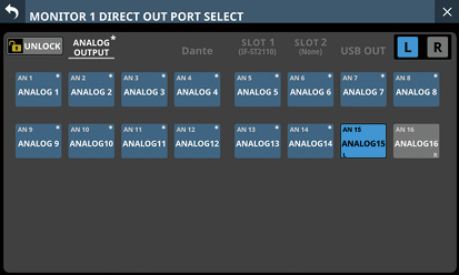
This screen shows the same content as the OUTPUT PORT SELECT Screen and is operated in the same way.
See “OUTPUT PORT SELECT screen” for details.
Direct OUT PORT button (MONITOR 2)
This shows the name of the output port that the MONITOR 2 DIRECT OUT signal is assigned to.
This button shows an abbreviated FIXED PORT LABEL in the upper line and a USER PORT LABEL in the lower line. If the USER PORT LABEL is undefined, the FIXED PORT LABEL will be shown.
Tap this button to open the MONITOR 2 DIRECT OUT PORT SELECT Screen where DIRECT OUT signal output ports for MONITOR 2 can be selected.
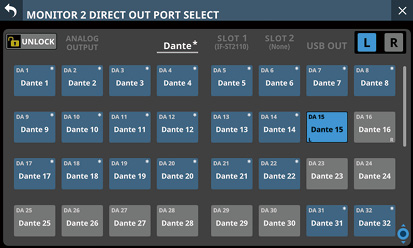
This screen shows the same content as the OUTPUT PORT SELECT Screen and is operated in the same way.
See “OUTPUT PORT SELECT screen” for details.
Direct OUT PORT VOLUME knob (MONITOR 2)
Use this to adjust the output level from the MONITOR 2 DIRECT OUT PORT.
Range: −∞ dB – +10 dB (default: 0 dB)
Turn LCD knob 5 (lit red) to adjust it.
LOCATION setting buttons (MONITOR 2)
Tap these buttons to change the Location setting of MONITOR 2. (The default setting is NONE.)
See “ Monitor Location setting area” for details about Location settings.
When the MONITOR 2 Location is set, “CR” or “ST” icons will be shown on the additional settings window and to the side of the MONITOR 2 display on the MONITOR 1/2 page.
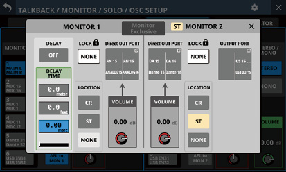
Appearance when MONITOR 2 Location set to “ST”
OUTPUT PORT button (MONITOR 2)
This shows the name of the output port that the MONITOR 2 OUTPUT signal is assigned to.
This button shows an abbreviated FIXED PORT LABEL in the upper line and a USER PORT LABEL in the lower line. If the USER PORT LABEL is undefined, the FIXED PORT LABEL will be shown.
Tap this button to open the OUTPUT PORT SELECT Screen where output ports for the MONITOR 2 OUTPUT signals can be selected.
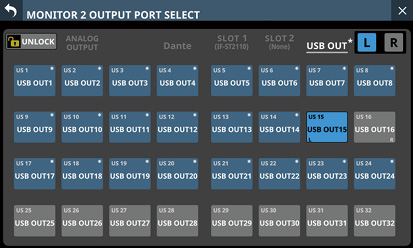
This screen shows the same content as the OUTPUT PORT SELECT Screen and is operated in the same way.
See “OUTPUT PORT SELECT screen” for details.
![]() button
button
Tap the ![]() button to close the additional settings window.
button to close the additional settings window.
Monitor Lock buttons
Tap one of these buttons to open a window where that monitoring source can be locked, selecting it for persistent monitoring use.
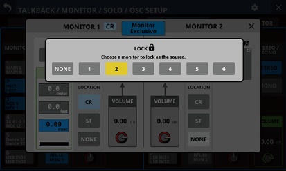
Tap an option to select the monitoring source to lock. (The default setting is NONE.)
NOTE
One monitoring source can be selected and locked each for MONITOR 1 and MONITOR 2.
A ![]() mark will appear on the MONITOR SELECT button that corresponds to the locked monitoring source. (See “Making monitor output settings”.)
mark will appear on the MONITOR SELECT button that corresponds to the locked monitoring source. (See “Making monitor output settings”.)
Making solo and built-in oscillator settings
Make solo and built-in oscillator settings on the SOLO/OSCILLATOR page of the TALKBACK / MONITOR / SOLO / OSC SETUP screen.
Tap Menu Screen > Mixer Setup > Talkback / Monitor / Solo / OSC to open this screen..
.jpg)
NOTE
This screen can also be opened by pressing either the SOLO or SOLO CLEAR key while pressing the MENU key. (See “16 - List of shortcut operations”.)
SOLO MODE buttons
Tap these buttons to set the solo function operation mode.
|
Option |
Meaning |
|
MIX (default) |
In solo mode, signals from modules that have their SOLO keys pressed are mixed for solo monitoring. |
|
EXCLUSIVE |
In solo mode, only the signal from the module that had its SOLO key pressed last is used for solo monitoring. |
The selected button will be highlighted.
SOLO TYPE buttons
Tap these buttons to set the solo function type.
|
Option |
Meaning |
|
PFL (default) |
Pre-fader signals are used for solo monitoring. |
|
AFL |
Signals after panning (post-fader for the MAIN L/R Master module) are used for solo monitoring. |
The selected button will be highlighted.
This shows the names of the output ports that the OUTPUT signal is assigned to.
This button shows an abbreviated FIXED PORT LABEL in the upper line and a USER PORT LABEL in the lower line. If the USER PORT LABEL is undefined, the FIXED PORT LABEL will be shown.
Tap this button to open the Solo DIRECT OUT PORT SELECT Screen where solo signal output ports can be selected.
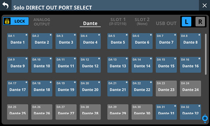
This screen shows the same content as the OUTPUT PORT SELECT Screen and is operated in the same way.
See “OUTPUT PORT SELECT screen” for details.
OSCILLATOR ASSIGN
Tap these buttons to set the outputs for the built-in oscillator signal. (These are off by default.)
Buttons for selected outputs will be highlighted.
NOTE
Outputs can be turned on/off independently even for stereo buses.
These buttons show the FIXED MODULE LABEL in the upper line and the USER MODULE LABEL in the lower line. (See “DISPLAY MODE page”.)
SOLO LEVEL knob
Use this to adjust the output level from the SOLO L/R bus.
Range: −∞ dB – +10 dB (default: 0 dB)
Turn LCD knob 3 (lit red) to adjust it.
SOLO CLEAR button
This button will appear highlighted when soloing is on for any of the modules.
When this button is highlighted, tap it to end soloing on all channels.
NOTE
This has the same function as the SOLO CLEAR key on the top panel.
Tap this button to turn the built-in oscillator signal ON and OFF (default).
When this is ON, the button will appear highlighted.
OSCILLATOR level meter
This shows the output level of the built-in oscillator.
OSC LEVEL knob
Use this to adjust the output level of the built-in oscillator.
Range: −36 dB – 0 dB (default: −20 dB)
Turn LCD knob 6 (lit red) to adjust it.
SIGNAL TYPE button
This shows the signal type of the built-in oscillator.
Tap this button to open the type selection menu.
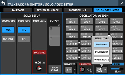
Options: SINE WAVE (default), PINK NOISE, WHITE NOISE
Tap an option button to close the menu, and show the selected signal type.
FREQ
This appears if the signal type is set to “SINE WAVE”.
Use this to adjust the output frequency of the built-in oscillator.
Options: 100 Hz, 440 Hz, 1 kHz (default), 10 kHz
Turn LCD knob 8 (lit blue) to adjust it.
On this screen, set and view the status of the built-in Dante module and an SB-16D connected via the built-in Dante module.
Tap Menu Screen > Rear Panel Setup > Dante Setup to open this page.
.jpg)
MODULE status
This shows the status of the Dante module.
|
Item |
Content |
|
Dante Device Name |
This shows the module name of the Dante device. |
|
Dante Module Staus |
This shows the status of the Dante module. |
|
Software Version |
This shows the version of the built-in Dante module. This is the same as the Product Version shown in Dante Controller. |
|
Dante Firmware Version |
This shows the firmware version of the Dante system. This is the same as the Dante Firmware Version shown in Dante Controller. |
|
Dante Model |
This shows the hardware type of the built-in Dante module. This is the same as the Dante Model shown in Dante Controller. |
NETWORK status
This shows the status of the Dante network.
When in Redundant mode, settings will be shown for the Primary connector on the left and for the Secondary connector on the right.
When in Switched (daisy-chain) mode, only the left side will be active.
|
Item |
Content |
|
Switch |
This shows the selected connection mode. Tap this area to open a window where Redundant or Switched mode can be selected. (default: Redundant) |
|
Addressing |
This shows the IP address setting mode. Tap this area to open a window where AUTO (DHCP) or STATIC can be selected. (default: AUTO (DHCP)) |
|
IP Address |
If the Addressing item is set to “AUTO”, this will show the assigned IP address. If it is set to “STATIC”, this will show the IP address set by the user. When the Addressing item is set to “STATIC”, tapping this area will open the IP ADDRESS Screen. (See “IP Address/Subnet Mask/Default Gateway setting procedures”.) |
|
Subnet mask |
If the Addressing item is set to “AUTO”, this will show the assigned subnet mask. If it is set to “STATIC”, this will show the subnet mask set by the user. When the Addressing item is set to “STATIC”, tapping this area will open the SUBNET MASK Screen. (See “IP Address/Subnet Mask/Default Gateway setting procedures”.) |
|
LINK Status |
This shows the Dante network link status. This will be shown in red if it is not 1 G. |
|
MAC Address |
This shows the MAC address of the Primary/Secondary Dante port. |
NOTE
To confirm Dante network settings, the Dante module must be restarted.
If Dante network settings have been changed, the APPLY button will appear highlighted.
Tap the APPLY button when it is highlighted to open a confirmation message.
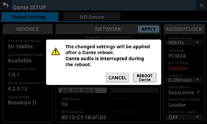
Tap the REBOOT Dante button to restart the Dante module.
ATTENTION
Be aware that Dante input and output sound will be interrupted while the Dante module is restarting.
AUDIO/CLOCK setting status
This shows the status of Dante audio signal and clock.
|
Item |
Content |
|
Sampling rate |
This shows the sampling frequency setting of the built-in Dante module. Tap this area to open a window where 48kHz or 96kHz can be selected. (default: 96 kHz) NOTE If the sampling rate is 48kHz, 64 IN and 64 OUT will be available. If it is 96kHz, this becomes 32 IN and 32 OUT. |
|
Encoding |
This shows the encoding setting. |
|
AES 67 Mode |
This shows the AES67 mode. |
|
Latency |
This shows the latency setting. Tap this area to open a window where the latency (0.25msec, 0.5msec, 1.0msec, 2.0msec or 5.0msec) can be selected. (default: 1.0msec) |
|
Clock Source |
This shows the Dante module clock source (Dante or Sonicview). Tap the |
|
Dante Clock Status |
This shows the Dante clock status (Leader, Follower or Unlock). “Unlock” will be shown in red. |
|
Preferred Leader |
This shows the Preferred Leader setting. Tap this area to open a window where ON or OFF can be selected. (default: OFF) |
Use this page to, for example, mount SB-16Ds, which are supported I/O devices, and make settings for them.
.jpg)
Device display area
This shows the ID numbers, model names (SB-16D) and Dante device module names for SB-16D units detected on the connected Dante network. SB-16D units that have different network addresses or are connected through routers will not be shown here.
Selected devices will be highlighted with yellow frames.
Tap the ![]() button to open the SB-16D control screen. (See “Control screen operations”.)
button to open the SB-16D control screen. (See “Control screen operations”.)
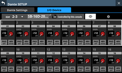
Scroll knob and scrollbar
If all the detected Dante devices cannot be shown on the screen at once, the scrollbar will appear and the scroll knob will be highlighted.
Drag the scrollbar to scroll the screen. The device display area () can also be scrolled by swiping up and down as well as by turning LCD knob 4.
Mount/unmount buttons
Use these buttons to mount SB-16D units and to unmount already mounted ones.
See the following for operation procedures.
“Mounting of devices connected to the Dante network”
“Mounting devices that are not on the Dante network”
Mounted Device area
This shows mounted devices.
The devices are shown with the following colors depending on status.
|
Item |
Status |
|
|
Device connected to the Dante network |
|
|
Virtual device that does not exist on the Dante network |
Selected devices and mounting positions will be highlighted with yellow frames.
.jpg)
Control privilege display area: This shows the control privilege status.
|
Item |
Explanation |
|
|
This Sonicview has control privileges. |
|
|
This Sonicview does not have control privileges. The named Sonicview has control privileges. Tap this to open a message confirming whether or not to request control. (See “Setting control privileges after mounting”.) |
|
|
Control is possible from any device. Tap this to open a message confirming whether or not to request control. (See “Setting control privileges after mounting”.) |
|
|
This Sonicview does not have control privileges, so operation is not possible from the Home Screen or MODULE Screen. Tap this to open a message confirming whether or not to request control. (See “Setting control privileges after mounting”.) |
|
|
Mounting is in process. |
This shows the module name. If no device with the same ID is connected to the same Dante network (when virtually-mounted), “Virtual” will be shown.
This shows the login status.
|
Item |
Explanation |
|
Logged In |
Information for this SB-16D can be acquired by this Sonicview. |
|
Logged Out |
Information for this SB-16D cannot be acquired by this Sonicview. (Login is not possible because this SB-16D is already mounted by 10 Sonicview units or a communication error occurred.) (See “Login failure”.) |
This shows the module name of the Dante device set in this SB-16D.
This shows the ID. If multiple devices with the same ID are connected to the same Dante network (when the same ID is duplicated), “ID” will be shown in red with a ![]() mark.
mark.
Tap this button to open the SB-16D control screen. (See “Control screen operations”.)
This sets whether Dante routing settings are automatically made according to the SB-16D mounting state or using Dante Controller.
Tap this button to turn it on/off.
|
Option |
Meaning |
|
ON (default) |
SB-16D and Sonicview Dante routing is set automatically according to the SB-16D mounting status. We recommend this when an SB-16D is the only Dante device connected to the Sonicview. |
|
OFF |
Dante routing will not be set even if an SB-16D is mounted. Use Dante Controller for routing. Use this setting when connecting Dante devices other than an SB-16D. |
When the AUTO ROUTING button is changed from “OFF” to “ON”, the following confirmation message will appear if executing automatic Dante routing changes the Dante input routing of this unit.
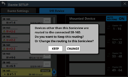
Tapping the KEEP button will switch the AUTO ROUTING button to “ON” but Dante routing settings will be retained as is. If an SB-16D is mounted after the AUTO ROUTING button is switched to “ON”, routing will occur automatically.
Tapping the CHANGE button will change the Dante routing according to the mounting status. In this case, output routing from the Sonicview to other Dante devices will be retained as is, and output routing from the Sonicview to mounted SB-16D unit will be added.
Example of Dante routing when the AUTO ROUTING button is OFF
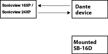
Dante routing state after the AUTO ROUTING button is switched to “ON” from the above state and the CHANGE button is tapped
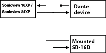
NOTE
If all the following conditions have been met when the CHANGE button is tapped, the preamp of the SB-16D assigned to the Insert Return port will be set to the line level standard settings as follows.
This unit has acquired the control privileges for the mounted SB-16D
The input port of the mounted SB-16D is assigned to the Insert Return port
Preamp settings
PAD: ON
Analog GAIN: 0
Phantom: OFF
If control privileges for the concerned SB-16D have not been acquired by this unit, preamp settings cannot be changed to line level standard settings, so the following message will be shown.
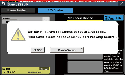
To use SB-16Ds as a Sonicview I/O boxes, they must be mounted (registered) in advance.
See the following for operation procedures.
“Mounting of devices connected to the Dante network”
“Mounting devices that are not on the Dante network”
A maximum of 4 SB-16D units can be mounted on a Sonicview.
If an SB-16D is mounted and control privileges acquired, this unit will be able to do the following.
Control SB-16D preamps
Control SB-16D preamps using snapshot recall
Control/use GPIO ports (expansion mode)
Control Dante output routing
The Sonicview manages SB-16D mounting status by ID. If no device with the same ID as the mounted ID is connected to the Dante network, “Virtual” will be shown instead of the device name.
If multiple devices with the same ID are connected to the same Dante network (when the same ID is duplicated), “ID” will be shown in red with ![]() marks for those devices.
marks for those devices.
If the ID of a mounted device is used by more than one device, the SB-16D that was recognized by the Sonicview first will be used. However, duplicate IDs must be resolved to show them on the SB-16D control screen. (See “Resolving duplicate IDs”.)
Moreover, an SB-16D with a duplicate ID that is later recognized by the Sonicview cannot be used.
If the AUTO ROUTING button on the I/O Device page is “ON”, the mounted SB-16D I/O ports and the main unit’s built-in Dante I/O will be assigned to Dante routing automatically when mounted according to the mounting position in the Mounted Device area (). See the table in “Dante routing” for details.
Mounting of devices connected to the Dante network
1.Tap a device in the left column on the Dante network that you want to mount.
The selected device will be shown with a yellow frame.
_MountStep1.jpg)
2.Tap the mounting destination on the right side (open mounting slot).
The selected mount destination will be shown with a yellow frame, and the central ![]() button will become highlighted (
button will become highlighted (![]() ).
).
3.Tap the central ![]() button to mount it in the selected destination on the right side.
button to mount it in the selected destination on the right side.
_MountStep2.jpg)
When mounting completes, a message will appear and information about control privileges after mounting will be shown in the top left of the mounting slot.
|
Item |
Explanation |
|
Pre Amp Control |
Control is possible from this Sonicview. |
|
Pre Amp Control by |
The named Sonicview has control privileges. Control is not possible from this Sonicview. (Sound will pass.) |
NOTE
If control privileges are not held, control of the preamps, GPIO (expansion mode), snapshot recall and output routing will not be possible from this Sonicview even when mounted.
If control privileges are acquired, control of the above items becomes possible, and sampling rate and reference level settings will be prioritized over those from other Sonicview units.
If all the following conditions are met when an SB-16D is mounted, the preamp of the SB-16D assigned to the Insert Return port will be set to the line level standard settings as follows.
This unit has acquired the control privileges for the mounted SB-16D
The input port of the mounted SB-16D has Dante routing as an input for this unit
The input port of the mounted SB-16D is assigned to the Insert Return port
Preamp settings
PAD: ON
Analog GAIN: 0
Phantom: OFF
If control privileges for the concerned SB-16D have not been acquired by this unit, preamp settings cannot be changed to line level standard settings, so the following message will be shown.
If the Sonicview with control privileges is not on the Dante network:
After the mounting indicator disappears, a mounting completed message will be shown. This message will disappear automatically after a few seconds.
_RequestControl@NoOneHasControl.jpg)
_GetControl.jpg)
If the Sonicview with control privileges is on the Dante network:
After mounting completes, tap the “Pre Amp Control by …” button. When the following message appears, tap the REQUEST button, and wait for approval from the Sonicview that has control privileges.
_DoYouRequestControl.jpg)
The following message will appear while waiting for permission. Tapping the CANCEL button will stop the permission waiting state and end the mounting operation.
_RequestingControl.jpg)
A permission request message will appear on the Sonicview with control privileges.
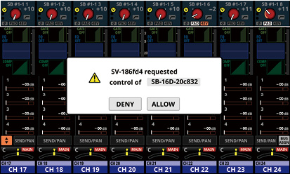
This message will disappear automatically if the CANCEL button is tapped on the requesting device before the response is given on the Sonicview with control privileges.
If a button in the permission request message on the Sonicview with control privileges is tapped, the following will appear on the requesting Sonicview.
Tapping the ALLOW button will cause a message confirming that control has been acquired to appear on the requesting device. This message will disappear automatically after 2 seconds.
_ControlAllowed.jpg)
Tapping the DENY button will open a message confirming refusal of the request. Tap the OK button to close the message.
_DenyTheRequest.png.jpg)
1.Tap the device that you want to unmount in the right column list.
The selected device will be shown with a yellow frame, and the central ![]() button will become highlighted (
button will become highlighted (![]() ).
).
2.Tap the central ![]() button.
button.
This unmounts the selected device, moving it to the list on the left.
_UnmountStep2.jpg)
If control privileges were held before unmounting, they will be cleared.
“Open Control” will be shown in the control privilege display area on other Sonicview units that have this device mounted.
_NoOneHasControl.jpg)
Mounting devices that are not on the Dante network
Devices that are not connected to the Dante network can be mounted virtually.
Connecting a device with a corresponding ID when the I/O Device page AUTO ROUTING button is “ON” will cause preamp and routing data to be applied.
1.Tap the ID at the very bottom of the list on the left to open a window where an ID number can be set for a virtually-mounted device.
_11_VirtualDeviceIDSetting.jpg)
2.Swipe the options up and down to select the ID to mount.
Selections can also be changed by turning the LCD Knobs 2 and 3, which are lit pink and yellow.
If an ID that is already being used on the Dante network is selected, that ID will be red and the APPLY button will appear gray, showing the setting cannot be made.
3.Tap the APPLY button to confirm setting changes.
The selected ID number will be shown.
_12_SetVirtualDeviceIDDone.jpg)
4.Tap the mounting destination on the right side (open mounting slot).
The selected mount destination will be shown with a yellow frame, and the central ![]() button will become highlighted (
button will become highlighted (![]() ).
).
5.Tap the central ![]() button to mount it in the selected position on the right side.
button to mount it in the selected position on the right side.
_13_MountVirtualDevice.jpg)
Setting control privileges after mounting
Control privileges can be requested after mounting.
1.Tap the control privilege display area for a mounted SB-16D with control privileges that have not been acquired to open a message.
_ConfirmRequestControl.png.jpg)
2.Tap the REQUEST button to start requesting control privileges.
Tap the CANCEL button to cancel requesting control privileges.
NOTE
If control privileges are not acquired, control of the preamps, GPIO (expansion mode), snapshot recall and output routing for that SB-16D will not be possible from this Sonicview even when mounted.
If control privileges are acquired, control of the above items becomes possible, and sampling rate and reference level settings for that SB-16D will be prioritized over those from other Sonicview units.
Resolving in the list on the right
1.Tap the ![]() button for a device with a duplicate ID to open the ID setting window.
button for a device with a duplicate ID to open the ID setting window.
_IDConflicted_ChangeIDMenu.jpg)
2.Swipe the options up and down to set the ID as desired.
Selections can also be changed by turning the LCD Knobs 2 and 3, which are lit pink and yellow.
NOTE
If an ID that is already being used on the Dante network is selected, that ID will be red and the APPLY button will appear gray, showing the setting cannot be made.
3.Tap the APPLY button to confirm setting changes.
The selected ID number will be shown.
_IDConflictResolved.jpg)
This resolves the duplication, and returns to the regular screen.
Resolving in the list on the left
1.Tap the ![]() button for a device with a duplicate ID.
button for a device with a duplicate ID.
This opens the control screen for the tapped device.

2.If “Controlled by this console” is shown to the right of the device name area, tap the ID area at the top left of the screen to open the ID setting window.
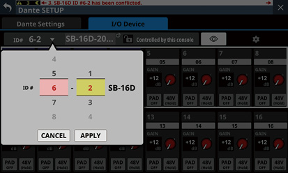
3.Swipe the options up and down to set the ID as desired.
Selections can also be changed by turning the LCD Knobs 2 and 3, which are lit pink and yellow.
NOTE
If an ID that is already being used on the Dante network is selected, that ID will be red and the APPLY button will appear gray, showing the setting cannot be made.
4.Tap the APPLY button to confirm setting changes.
The selected ID number will be shown.
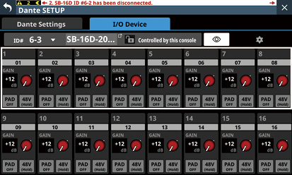
This resolves the duplication, and returns to the regular screen.
Alerts and errors shown related to the SB-16D
When switching from virtual mounting to actual mounting:
The following message window will appear on the right touchscreen.
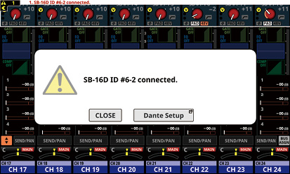
Tap the CLOSE button to close the message.
Tap the Dante Setup button to open the Dante SETUP Screen I/O Device page on the right touchscreen. In addition, the following alert message will appear at the top of every touchscreen.
|
SB-16D ID #xx-xx connected. |
Tap this alert message to open the Dante SETUP Screen I/O Device page.
To close the alert message shown at the top of the screen, tap the ![]() button on the corresponding message on the ERROR page of the INFORMATION screen. (See “ERROR page”.)
button on the corresponding message on the ERROR page of the INFORMATION screen. (See “ERROR page”.)
When switching from actual mounting to virtual mounting:
When a mounted SB-16D is disconnected from the Dante network and becomes virtually mounted, the following error message will appear at the top of every touchscreen.
|
SB-16D ID #xx-xx has been disconnected. |
Tap this error message to open the Dante SETUP Screen I/O Device page.
This error message can be resolved in the following ways.
If the SB-16D returns to the Dante network, the error will be resolved automatically and the error message at the top of the screen will disappear.
Tapping the ![]() button on the corresponding error message on the ERROR page of the INFORMATION screen will close the error message at the top of the screen.
button on the corresponding error message on the ERROR page of the INFORMATION screen will close the error message at the top of the screen.
Unmounting the corresponding device using the I/O DEVICE page of the Dante Setup screen will resolve the error and close the error message at the top of the screen.
When an ID is used more than once:
When another SB-16D that has the same ID as a mounted SB-16D is connected to the Dante network, resulting in duplicate IDs, the following error message will appear at the top of every touchscreen.
|
SB-16D ID #xx-xx has a ID conflict. |
Tap this error message to open the Dante SETUP Screen I/O Device page.
In this case, the device that was mounted first is given priority, so it has no impact on operation as a mixer.
If an ID becomes duplicated when there is a remaining alert message that occurred when switching from virtual mounting to actual mounting, the error message will appear after the alert message is removed.
This error message can be resolved in the following ways.
Resolving the duplicate ID using the I/O DEVICE page of the Dante screen will close the error message at the top of the screen.
If the device causing duplication is removed from the Dante network, normal mounting status will be restored and the error message at the top of the screen will be closed.
When this error message is resolved, the following error resolution message will be added to the ERROR page of the INFORMATION screen.
|
SB-16D ID #xx-xx conflict has been resolved. |
Restrictions when routing during 96kHz operation with Dante Controller
When the AUTO ROUTING button is set to “OFF”, “Sonicview Dante I/O” and “![]() 1-16”, for example, will not be shown in the list on the right of the I/O Device page.
1-16”, for example, will not be shown in the list on the right of the I/O Device page.
_Routing-DanteController.jpg)
Instead, the message below will appear.
|
Use the Dante Controller for Routing. |
If the Sampling rate is set to “96kHz” on the Dante Settings page of the Dante SETUP screen, the list on the right of the I/O Device page will not show “![]() 33–48” and “
33–48” and “![]() 49–64” in the bottom two mounting slots.
49–64” in the bottom two mounting slots.
Alternatively, the message shown below will appear.
_DanteFs-96kHz.jpg)
In this case, operations to acquire control privileges are necessary after mounting.
They will not be acquired automatically when mounted.
Immediately after mounting, “Pre Amp Control OFF” will be shown in the control privilege display area.
If no IF-DA64 (Dante card) is installed:
Tapping the control privilege display area will open the following message.
|
IF-DA64 is required to enable Pre Amp Control. [CANCEL] |
Tap the CANCEL button to close the message window and return to the previous screen. In this case, preamp control is not possible from this unit.
If an IF-DA64 (Dante card) is installed:
Tapping the control privilege display area will open the following message.
|
Route as follows by Dante Controller. Do you want to enable Pre Amp Control? [CANCEL] [ENABLE] |
Tap the CANCEL button to close the message window and return to the previous screen. In this case, preamp control is not possible from this unit.
Tapping the ENABLE button will set the control privilege and “Pre Amp Control” will be shown in the control privilege display area.
If another Sonicview, for example, already has SB-16D control privileges:
Tapping the control privilege display area will open the following message.
|
Route as follows by Dante Controller. Do you request control? Sonicview XXX has Pre Amp control. [CANCEL] [REQUEST] |
After this, control privileges can be acquired by following the procedures from step 5 in “Mounting of devices connected to the Dante network”.
By acquiring control privileges with the above methods, preamp control becomes possible from the assigned module of the SLOT that the IF-DA64 (Dante card) is installed in as an input source.
*This appears when an SB-16D is mounted in the 3rd mounting slot and an IF-DA64 (Dante card) is installed in SLOT 1.
If an SB-16D is mounted in the 4th mounting slot and an IF-DA64 (Dante card) is installed only in SLOT 2, the following message will appear.
|
Route as follows by Dante Controller. |
One SB-16D can be accessed simultaneously from a maximum of 10 Sonicview units.
If 10 units would be exceeded, the Sonicview that tries to access that SB-16D will fail (login failure) and will not be able to control that SB-16D.
“Logged Out” will be shown at the top right of mounted devices for which logging in failed.
_Logout.jpg)
Tap the ![]() button for unmounted or mounted devices to show the following messages that explain generally why login failed.
button for unmounted or mounted devices to show the following messages that explain generally why login failed.
Tap the OK button in the message to close it.
The content of the message depends on the reason login failed.
If 10 units are already logged in
|
Login failed. Exceeded maximum number of connections. |
If login was not possible because of a communication error
|
Login failed. TCP Error. |
If logging in fails when an SB-16D is mounted, mounting will be executed, but the above messages will be shown.
The following items are possible or not possible using mounted devices with which login failed.
Possible
Input Dante Routing from the SB-16D to the Sonicview can be set with this unit, and the input sound of this SB-16D can be input to this unit.
Setting routing with Dante Controller makes inputting and outputting sound from this SB-16D possible.
Not possible
Output Dante routing from the Sonicview to the SB-16D cannot be set with this unit. For this reason, sound from this unit cannot be output from this SB-16D.
Acquiring control privileges and changing/confirming preamp and other settings are not possible.
Responding to login failure errors
If any Sonicview units are showing the operation screen for that unmounted SB-16D, close that screen.
If that SB-16D is mounted on more than 10 Sonicview units, unmount it from a Sonicview unit that does not need it.
If already mounted and logging in failed, after doing the above, unmount it and then mount it again.
If the above responses do not resolve the issue, turn the SB-16D power off once and wait a few seconds before turning the power on again.
Synchronizing audio settings
If the Sonicview has control privileges after mounting, the SB-16D sampling rate and reference level (both analog and digital) settings will automatically be synchronized with those of that Sonicview. Moreover, it will also be set as the device for snapshot recall and set as the device with priority for Dante output routing.
Routing of Dante I/O for mounted SB-16Ds and the Sonicview can be done automatically.
On the other hand, routing can be left to Dante Controller and the Sonicview can be set to not do routing.
Use the AUTO ROUTING button on the I/O Device page to set this. (See “ AUTO ROUTING button”.)
_ThisConsole.jpg)
To conduct Dante routing from the Sonicview for SB-16D units mounted on it, set the AUTO ROUTING button to “ON”.
Dante routing will be set automatically when mounted.
In this case, depending on the SB-16D mounting position, the mounted SB-16D I/O port and this unit’s built-in Dante I/O will be routed for Dante automatically when mounting occurs as shown below.
When Sync Clock is 48 kHz
|
Mounting position in Mounted Device area |
Routing destination |
|
Top |
Built-in Dante I/O 1–16 of this unit |
|
2nd from top |
Built-in Dante I/O 17–32 of this unit |
|
3rd from top |
Built-in Dante I/O 33–48 of this unit |
|
4th from top |
Built-in Dante I/O 49–64 of this unit |
When Sync Clock is 96 kHz
|
Mounting position in Mounted Device area |
Routing destination |
|
Top |
Built-in Dante I/O 1–16 of this unit |
|
2nd from top |
Built-in Dante I/O 17–32 of this unit |
|
3rd from top |
This will not be routed automatically. Use Dante Controller to route Dante I/O 1–16 for the IF-DA64 installed in this unit and Dante I/O 1–16 for the mounted SB-16D. |
|
4th from top |
This will not be routed automatically. Use Dante Controller to route Dante I/O 17–32 for the IF-DA64 installed in this unit and Dante I/O 1–16 for the mounted SB-16D. |
NOTE
When the AUTO ROUTING button is changed from “OFF” to “ON”, if executing automatic Dante routing changes the Dante input routing of this unit, the following message will appear to confirm whether to match the routing with the mounting status.
|
Devices other than this Sonicview are routed to the mounted SB-16D. Do you want to KEEP the routing? Or Change the routing to this Sonicview? [KEEP] [CHANGE] |
Tapping the KEEP button will switch the AUTO ROUTING button to “ON” but Dante routing settings will be retained as is. If an SB-16D is mounted after the AUTO ROUTING button is switched to “ON”, routing will occur automatically.
Tapping the CHANGE button will change the Dante routing according to the mounting status. In this case, output routing from the Sonicview to other Dante devices will be retained as is, and output routing from the Sonicview to mounted SB-16D unit will be added.
Example of Dante routing when the AUTO ROUTING button is OFF
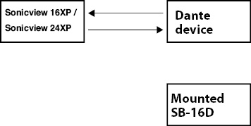
Dante routing state after the AUTO ROUTING button is switched to “ON” from the above state and the CHANGE button is tapped
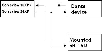
To conduct Dante routing for the Sonicview from Dante Controller, set the AUTO ROUTING button to “OFF”.
This will enable routing from Dante Controller.
When set to conduct Dante routing from Dante Controller, routing settings cannot be conducted from the Sonicview even for SB-16D units.
NOTE
Routing for mounted SB-16Ds will be retained as is. Routing will not occur automatically if an SB-16D is mounted after the AUTO ROUTING button is set to “OFF”.
Preamp control as a Sonicview I/O expansion
From the operation screen of the module that has the built-in Dante input port routed, input connector preamps of SB-16Ds that have been routed by Dante to this Dante input port can be operated.
In this case, they can be operated in the same way as the built-in analog input preamps of the Sonicview.
Only if all the following conditions are all met, preamps can be operated on the Home Screen, MODULE (OVERVIEW) screen and MODULE (INPUT) screen.
A Dante port is assigned to the module
The SB-16D Dante port is routed to this Dante port
The SB-16D that is routed to this Dante port is mounted on the Sonicview and control privileges are held, or it is virtually mounted
Example of appearance when mounted and control privileges are held
In this case the same preamp settings will be shown as would be when routing the built-in analog input jacks.
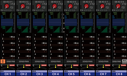
.jpg)
.jpg)
Example of appearance when mounted but control privileges are not held
In this case, the SB-16D preamp settings can be shown, but the GAIN knob, PAD buttons and 48V buttons will appear black and cannot be operated.
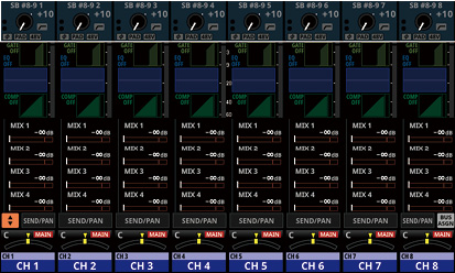
.jpg)
.jpg)
Example of appearance when virtually mounted
In this case the same preamp settings will be shown as would be when routing the built-in analog input jacks, and ![]() marks are shown on routing settings.
marks are shown on routing settings.
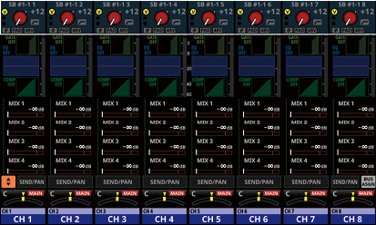
.jpg)
.jpg)
SB-16D full control
Whether they are mounted or not, SB-16D units that are connected to the same Dante network can be fully controlled from a Sonicview.
NOTE
If another Sonicview has SB-16D control privileges, its setting values can be shown, but they cannot be controlled. In this case, an ![]() icon will appear at the top of the SB-16D control screen and the Dante device module name of the Sonicview that has control privileges will be shown.
icon will appear at the top of the SB-16D control screen and the Dante device module name of the Sonicview that has control privileges will be shown.
1.Tap Menu Screen > Rear Panel Setup > Dante Setup to open the Dante SETUP screen and tap the I/O Device tab.
2.Tap the ![]() button for the device you want to control.
button for the device you want to control.
This opens the control screen.
.jpg)
ID
This shows the current ID.
Tap this area to open a window where the ID can be changed.
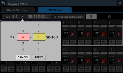
Swipe the options up and down to change the ID.
Selections can also be changed by turning the LCD Knobs 2 and 3, which are lit pink and yellow.
Tap the APPLY button to change the selected ID.
Tap the CANCEL button to close the window without changing the ID.
NOTE
If an ID that is already being used on the Dante network is selected, that ID will be red and the APPLY button will appear gray, showing the setting cannot be made.
Changing the ID when mounted could cause it to become unmounted.
Device name
This shows the module name of the SB-16D Dante device.
Tap this area to enable changing the module name of the Dante device.
If the device is virtually mounted, “---” will appear and tapping will not enable changing.
Control privilege status
This shows the control privilege status.
If this unit has control privileges, ![]() and “Controlled by this console” will be shown.
and “Controlled by this console” will be shown.
If this unit does not have control privileges, ![]() and “Controlled by [Dante device module name of the Sonicview that has control privileges]” will be shown.
and “Controlled by [Dante device module name of the Sonicview that has control privileges]” will be shown.
In the following cases, nothing will be shown.
If no device has control privileges for that SB-16D
If the device is virtually mounted
![]() button
button
Tap this button to send an Identify command to the SB-16D. The SB-16D that receives the Identify command will respond by blinking its SIG and STATUS indicators, making it possible to confirm the corresponding device. Tapping this button again when an SB-16D is responding will send it another Identify command, which will cause it to stop responding.
This button is not shown for devices that are virtually mounted.
![]() button
button
Tap this button to open the Settings Screen where settings other than those related to preamp operation can be checked.
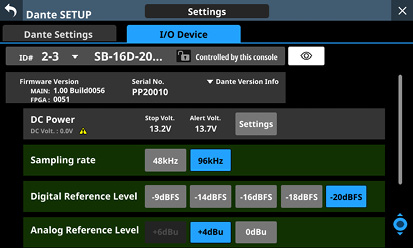
Channel modules
Work with channel names, GAIN knobs, PAD buttons and 48V buttons in this area.
Tapping a channel name will open the RENAME screen where it can be edited.
GAIN levels of the channels selected by the frame can be adjusted using the 1–8 LCD knobs that are lit red.
Tap a PAD button to turn the −20 dB pad on/off. When this button is on, it will appear highlighted.
Press and hold the 48V button to turn phantom power (+48V) on/off. When phantom power is on, the button will be highlighted.
GAIN knobs, PAD buttons and 48V buttons can also be used with virtually mounted devices.
If another Sonicview has control privileges for the SB-16D shown, it will appear as follows and cannot be controlled.
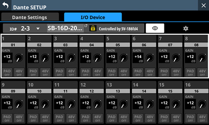
Example of appearance when control privileges are not held
Settings screen
.jpg)
.jpg)
Firmware Version
This shows the SB-16D firmware versions.
If the device is virtually mounted, “---” will appear in place of the numbers.
Serial No.
This shows the serial number of the SB-16D.
“---” will appear if the device is virtually mounted.
Dante Version Info
This shows the SB-16D Dante module firmware version.
If the device is virtually mounted, nothing will be shown even if tapped.
Tap this area to open a Dante information window.
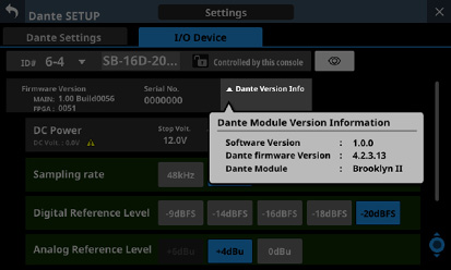
Scroll knob and scrollbar
This scroll bar shows the position of the setting items currently shown on the screen relative to all items on the Settings Screen.
NOTE
To view setting items not shown on the screen, swipe the setting items area up and down to scroll the screen.
LCD knob 8, which is lit light blue, can also be turned to scroll the screen.
DC Power information
SB-16D DC power status is shown and related settings can be made here.
|
Item |
Explanation |
|
DC Volt. |
This shows the current voltage and status of the DC power supply. A green indicator will be shown if the DC power supply is providing power normally. If the alert display setting is on, and the DC power supply voltage has become less than the alert voltage, an No indicator will be shown if the DC power supply is not providing power (if the DC power supply voltage is below the stop voltage). |
|
Stop Volt. |
This shows the stop voltage setting value. |
|
Alert Volt. |
This shows the setting value for the voltage that triggers showing an alert. If the Alert Voltage ON/OFF button is set to “OFF” in the DC Power settings window, “--.-V” will be shown here. |
|
Settings button |
Tap this button to open the DC Power settings window. (See “DC Power settings”.) |
“---” will appear for all the settings if the device is virtually mounted. In addition the Settings button will appear gray and cannot be used.
Sampling rate buttons
These set the sampling frequency for the SB-16D.
The selected button will be highlighted.
Digital Reference Level buttons
Use these to set the digital reference level of the SB-16D.
The selected button will be highlighted.
Analog Reference Level buttons
Use these to set the analog reference level of the SB-16D.
The selected button will be highlighted.
NOTE
The settings of Sampling rate (), Digital Reference Level () and Analog Reference Level () buttons with green backgrounds are linked to the settings of the Sonicview that has control privileges. For this reason, settings cannot be changed on this Settings screen if mounted.
For virtually mounted devices, Sampling rate (), Digital Reference Level () and Analog Reference Level () button settings will all appear gray and cannot be operated.
LED Brightness buttons
Use the ![]() and
and ![]() buttons to set the brightness of the SB-16D indicators.
buttons to set the brightness of the SB-16D indicators.
Range: 0 – 3 (default 3)
If the device is virtually mounted, “–” will appear and the buttons will be gray and cannot be operated.
GPIO Extension
Tap the Settings button to open the GPIO Extension Settings Screen. (See “GPIO Extension Settings Screen”.)
Virtually-mounted devices can also be operated.
Network Settings
Tap the Dante button to open the Dante Network Settings on the Network Settings Screen. (See “Dante Network Settings”.)
Tap the Controller button to open the Controller Network Settings on the Network Settings Screen. (See “Control Network Settings”.)
If the device is virtually mounted, the Dante and Controller buttons will be gray and the settings screen cannot be opened.
Factory Reset button
Tap the Reset button to open a window where settings can be restored to their factory default values. (See “Factory Reset”.)
If the device is virtually mounted, this button will be gray and cannot be operated.
Tap the Settings button in the DC Power area to open the following DC Power settings window.
.jpg)
Stop Voltage: This sets the stop voltage.
Use LCD knob 4, which is lit light blue, to adjust it.
Range: 11.0 – 27.0 V (in steps of 0.1 V, default 11.0 V)
If the SB-16D is operating with only DC power supply, it will shut down if the DC power supply goes below this voltage.
If DC power is supplied from a battery, set the stop voltage according to the battery specifications. In all other cases, set this to a minimum of 11.0 V (the default value).
Alert Voltage: This sets the alert voltage.
Use LCD knob 5, which is lit green, to adjust it.
Range: OFF, 11.0 – 28.0 V (in steps of 0.1 V, default 11.5 V)
When the Stop Voltage setting is changed, this is automatically set +0.5V higher than the Stop Voltage.
Change this setting to adjust the timing if the alert is shown too quickly or too late.
DC Voltage: This shows the current DC input voltage.
Alert Voltage ON/OFF button: Tap this button to turn the alert message on/off. (Default: ON)
When ON, if the DC power supply voltage becomes less than the alert voltage, the following alerts will be shown.
SB-16D DC POWER indicator blinks
![]() indicator appears in DC Power area ()
indicator appears in DC Power area ()
Alert Reset button: Tap this button to reset the Alert Voltage setting to the default value (Stop Voltage +0.5 V).
CANCEL button: Tap this button to discard the changes in the DC Power settings window and close it.
SET button: Tap this button to confirm the values in the DC Power settings window and close it.
GPIO Extension Settings Screen
The SB-16D GPIO port has the following functions.
GPIO-IN
Muting control of SB-16D input and output signals (Local mode function)
Mounted Sonicview extension GPIO-IN port operation (Extension mode function)
GPIO-OUT
Tally output for muting states of SB-16D input and output signals (Local mode function)
Mounted Sonicview extension GPIO-OUT port operation (Extension mode function)
The following settings to use these functions can be made on this screen.
.jpg)
ALL Extension mode
.jpg)
ALL Local mode
.jpg)
Individual mode
ID
This shows the current ID.
Tap this area to open a window where the ID can be changed.
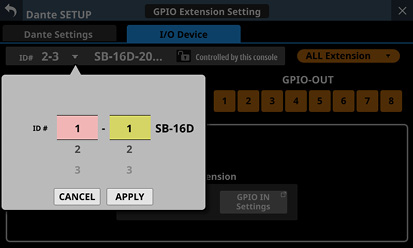
Swipe the options up and down to change the ID.
Selections can also be changed by turning the LCD Knobs 2 and 3, which are lit pink and yellow.
Tap the APPLY button to change the selected ID.
Tap the CANCEL button to close the window without changing the ID.
NOTE
If an ID that is already being used on the Dante network is selected, that ID will be red and the APPLY button will appear gray, showing the setting cannot be made.
Changing the ID when mounted could cause it to become unmounted.
GPIO port overall operation mode
This shows the overall operation mode for the GPIO port.
Tap this area to open a window where the overall operation mode for the GPIO ports of the SB-16D can be changed.
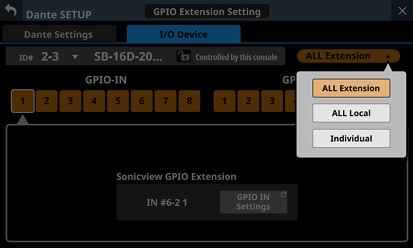
|
Option |
Explanation |
|
ALL Extension |
The ALL Extension mode setting uses all GPIO ports as GPIO extension pins of the Sonicview that the SB-16D is mounted in. |
|
ALL Local |
The ALL Local mode setting uses all GPIO ports as pins that do the following.
|
|
Individual |
In this mode, the operation of each GPIO port is set individually. |
Tap an option to switch the overall operation mode for the GPIO port of the SB-16D.
Pin number buttons
Tap this area to select a pin and show its settings in the Sonicview GPIO Extension display area (), the operation/action mode switching buttons for the individual pin () and the input/output signal selection status display area ().
When the overall operation mode for GPIO ports is “ALL Local” or “Individual”, tapping a pin number button will outline that button with a white frame.
Sonicview GPIO Extension display area
The GPIO IN Settings (when GPIO-IN pin selected) or GPIO OUT Settings (when GPIO-OUT pin selected) button is shown when the operation mode for the selected GPIO port is as follows.
When the GPIO port overall operation mode () is “ALL Extension”
When the GPIO port overall operation mode () is “Individual” and the operation/action mode button () is “Extension”
The selected GPIO port is used as a GPIO extension pin of the Sonicview that has the subject SB-16D mounted.
Set this with the GPIO-IN and GPIO-OUT pages on the USER DEFINED CONTROLS Screen of the Sonicview that has the subject SB-16D mounted.
Operation/action mode switching buttons for individual ports
These show the operation mode for the selected GPIO port in the following cases.
When GPIO port overall operation mode () is “ALL Local”
When the GPIO port overall operation mode () is “Individual”
These show the operation and action modes of the selected GPIO Port.
Tap these buttons to switch the operation and action modes of the individual port.
For GPIO IN ports
|
Option |
Explanation |
|
Extension |
The Extension mode setting uses the selected ports as GPIO extension pins of the Sonicview that the SB-16D is mounted in. This can only be selected when the GPIO port overall operation mode ( |
|
Local / Closed-Toggle |
In this mode, when the selected IN port becomes shorted (Closed), the SB-16D input/output signal selected in the input/output signal selection status area ( |
|
Local / Closed-Mute |
In this mode, when the selected IN port becomes shorted (Closed), the SB-16D input/output signal selected in the input/output signal selection status area ( |
|
Local / Closed-Unmute |
In this mode, when the selected IN port becomes shorted (Closed), the SB-16D input/output signal selected in the input/output signal selection status area ( |
For GPIO OUT ports
|
Option |
Explanation |
|
Extension |
The Extension mode setting uses the selected ports as GPIO extension pins of the Sonicview that the SB-16D is mounted in. This can only be selected when the GPIO port overall operation mode ( |
|
Local / Mute-Closed |
In this mode, when the SB-16D input/output signal selected in the input/output signal selection status area ( |
|
Local / Unmute-Closed |
In this mode, when the SB-16D input/output signal selected in the input/output signal selection status area ( |
Input/output signal selection status
These show the operation mode for the selected GPIO port in the following cases.
When GPIO port overall operation mode () is “ALL Local”
When the GPIO port overall operation mode () is “Individual” and the individual port operation/action mode button () is “Local / xxxxx”
When a GPIO-IN pin is selected, the SB-16D input/output signal that is subject to muting control is selected according to that pin.
Up to 16 can be selected for muting control by GPIO-IN pin.
If the selectable number is exceeded, the check fields will be shown in gray and become unselectable.
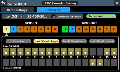
When a GPIO-OUT pin is selected, this selects the SB-16D input/output signal for mute/unmute status tally output from the selected pin.
A maximum of 16 input/output signals of the SB-16D used for tally output can be selected. If the selectable number is exceeded, the check fields will be shown in gray and become unselectable.
When multiple input/output signals are selected, tally output will occur if any of the selected input/output signals are muted (if set to Local / Mute - Closed) or unmuted (if set to Local / Unmute - Closed).
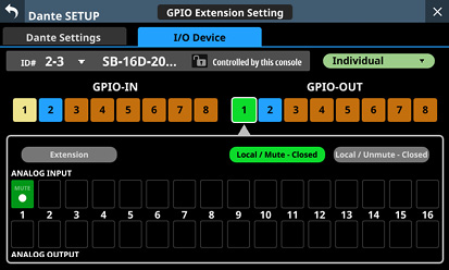
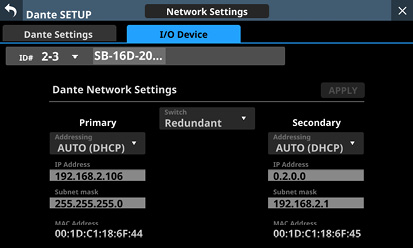
This shows the status of the Dante network settings for the SB-16D.
When in Redundant mode, settings will be shown for the Primary connector on the left and for the Secondary connector on the right.
When in Switched (daisy-chain) mode, only the left side will be active.
|
Item |
Content |
|
Switch |
This shows the selected connection mode. Tap this area to open a window where Redundant or Switched mode can be selected. (default: Redundant) |
|
Addressing |
This shows the IP address setting mode. Tap this area to open a window where AUTO (DHCP) or STATIC can be selected. (default: AUTO (DHCP)) |
|
IP Address |
If the Addressing item is set to “AUTO”, this will show the assigned IP address. If it is set to “STATIC”, this will show the IP address set by the user. When the Addressing item is set to “STATIC”, tapping this area will open the IP ADDRESS Screen. (See “IP Address/Subnet Mask/Default Gateway setting procedures”.) |
|
Subnet mask |
If the Addressing item is set to “AUTO”, this will show the assigned subnet mask. If it is set to “STATIC”, this will show the subnet mask set by the user. When the Addressing item is set to “STATIC”, tapping this area will open the SUBNET MASK Screen. (See “IP Address/Subnet Mask/Default Gateway setting procedures”.) |
|
LINK Status |
This shows the Dante network link status. This will be shown in red if it is not 1 G. |
|
MAC Address |
This shows the MAC address of the Primary/Secondary Dante port. |
To confirm Dante network settings for the SB-16D, the SB-16D Dante module must be restarted.
If SB-16D Dante network settings have been changed, the APPLY button will appear highlighted.
Tap the APPLY button when it is highlighted to open a confirmation message.
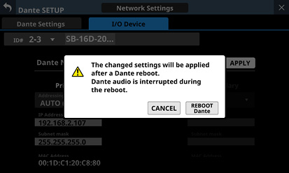
Since tapping the CANCEL button will not restart the unit, the settings will be as is but will not be applied to operation.
Tap the REBOOT Dante button to confirm the changes and restart the SB-16D Dante module.
After restarting, the settings will be applied to operation.
ATTENTION
Be aware that SB-16D Dante input and output sound will be interrupted while the SB-16D Dante module is restarting.
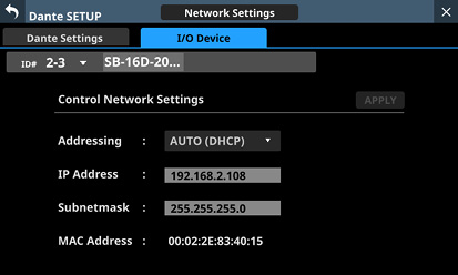
This shows the status of the Dante network settings for SB-16D control.
|
Item |
Content |
|
Addressing |
This shows the IP address setting mode. Tap this area to open a window where AUTO (DHCP) or STATIC can be selected. (default: AUTO (DHCP)) |
|
IP Address |
If the Addressing item is set to “AUTO”, this will show the assigned IP address. If it is set to “STATIC”, this will show the IP address set by the user. When the Addressing item is set to “STATIC”, tapping this area will open the IP ADDRESS Screen. (See “IP Address/Subnet Mask/Default Gateway setting procedures”.) |
|
Subnet mask |
If the Addressing item is set to “AUTO”, this will show the assigned subnet mask. If it is set to “STATIC”, this will show the subnet mask set by the user. When the Addressing item is set to “STATIC”, tapping this area will open the SUBNET MASK Screen. (See “IP Address/Subnet Mask/Default Gateway setting procedures”.) |
|
MAC Address |
This shows the MAC address for SB-16D control. |
If Dante network settings for SB-16D control have been changed, the APPLY button will appear highlighted.
When settings are applied, the SB-16D Dante network connection will be interrupted once. For this reason, tap the APPLY button when it is highlighted to open a confirmation message.
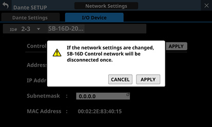
Tap the CANCEL button to cancel the changes and restore the previous state.
Tap the APPLY button to confirm the changes.
1.Tap the Reset button to open a window where settings can be restored to their factory default values.
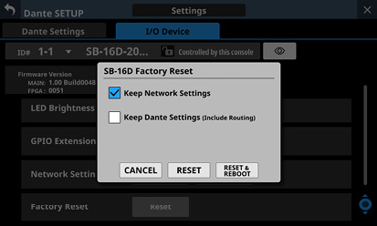
|
Item |
Explanation |
|
Keep Network Settings |
If the check mark ( If the check mark ( (This has a check ( |
|
Keep Dante Settings (Include Routing) |
If the check mark ( If the check mark ( (This does not have a check ( |
2.Add check marks (![]() ) for the settings that you want to retain.
) for the settings that you want to retain.
Remove check marks (![]() ) for the settings that you want to restore to factory defaults.
) for the settings that you want to restore to factory defaults.
NOTE
If check marks (![]() ) are added to both, only settings that are not related to the Dante network and Dante will be restored to their factory defaults.
) are added to both, only settings that are not related to the Dante network and Dante will be restored to their factory defaults.
3.Tapping the RESET or RESET & REBOOT button will open the following warning messages in a window.
Message if Keep Network Settings does not have a check mark (![]() ):
):
|
Network may be disconnected. |
Message if Keep Dante Settings (Include Routing) does not have a check mark (![]() ):
):
|
Audio will be interrupted. Dante routing will be cleared. |
Message when the RESET & REBOOT button is tapped:
|
Audio will be interrupted. |
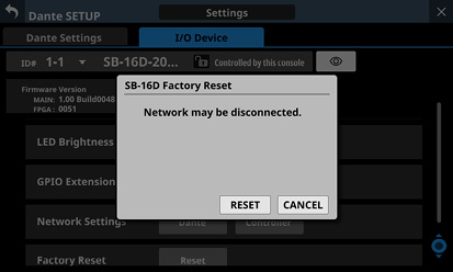
Message if Keep Network Settings does not have a check mark (![]() )
)
4.Tap the RESET button in the warning message to close the window and restore the following items to their factory default settings.
Settings without check marks (![]() )
)
Settings other than those for Dante network and Dante
ATTENTION
If the RESET & REBOOT button is tapped, after settings are restored to their factory defaults, the I/O Device page of the Dante Setup screen will open. Moreover, until the reset SB-16D has completed restarting it will be disconnected from the Dante network.
Tap the CANCEL button to close the window without changing the settings.
Using GPIO extension functions
If the SB-16D GPIO pin operation mode is set to “Extension”, they can be used as Sonicview GPIO extension pins.
This setting can also be made for virtually mounted SB-16D units.
By storing the settings in the Sonicview, online setting is possible.
Setting procedure
1.Following the instructions in “GPIO Extension Settings Screen” for the “Overall operation mode for the GPIO port buttons” () or “ Operation mode switching buttons for individual ports” (), set the operation mode for the ports you want to use as a GPIO extension for this unit to “Extension”.
2.Use the following procedures to open GPIO-IN and GPIO-OUT screens.
Tap Menu Screen > Rear Panel Setup > GPIO Input Setup
Tap Menu Screen > Rear Panel Setup > GPIO Output Setup
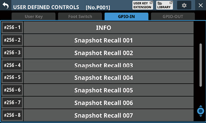
3.Use LCD knob 8 to scroll the list of settings for groups of 8 ports that correspond to mounting positions.
In the SB-16D GPIO pin name area, SB-16D IDs and port numbers are shown in a “#ID [port number]” format.
If the device is virtually mounted, the GPIO port name background will appear yellow.
Ports with operation mode set to Extension in the list will be highlighted.
Ports with operation mode set to Local in the list will be shown in gray.
4.Tap the port you want to set in the list and assign functions using the same procedures as with the unit’s built-in GPIO.
Procedures for Dante connection with SB-16Ds
This explains procedures for connecting an SB-16D as a stage box to this unit, and controlling its preamps from modules with built-in Dante ports assigned in the same way as built-in analog inputs.
Dante connections with SB-16Ds
When this unit is operating at 48 kHz, up to 4 SB-16D units can be connected without Dante Controller.
When this unit is operating at 96 kHz, up to 2 SB-16D units can be connected without Dante Controller.
In all other cases, setting using Dante Controller will be necessary.
Procedures for Dante connection with this unit and one SB-16D
In this case, Dante connection without using Dante Controller is possible whether this unit’s built-in Dante “Sampling rate” is using 48kHz or 96kHz operation. Moreover, controlling a preamp of that SB-16D from a module with a built in Dante port assigned is possible.
1.If multiple SB-16D units are connected to the Dante network, set IDs that are not duplicated on them in advance in order to enable their identification. For details about ID setting procedures, see the SB-16D operation manual.
2.Connect the following Dante ports to the same Dante network.
Dante ports built into this unit
SB-16D Dante ports
NOTE
When using only one of these units and one SB-16D, their Dante ports can be connected directly as shown below.
.jpg)
3.Set the Dante routing control method.
Tap Menu Screen > Rear Panel Setup > Dante Setup to open the Dante SETUP screen and tap the I/O Device tab.
4.Set the AUTO ROUTING button to “ON”.
5.Follow the procedures in “Mounting of devices connected to the Dante network”, and mount the selected SB-16D as the top item in the Mounted Device list.
Through these procedures, the Dante I/O ports of this unit and the one SB-16D unit are routed by Dante as follows.
|
Dante I/O ports of this unit |
SB-16D Dante I/O ports |
|
Dante I/O 1–16 of this unit |
SB-16D Dante I/O 1–16 |
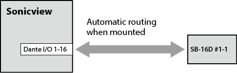
As a result, the preamps (Analog GAIN, PAD ON/OFF, Phantom ON/OFF) of the corresponding SB-16D INPUT can be operated on the Home Screen and MODULE screen of the module that has Dante IN 1–16 inputs assigned.
|
Module that can operate SB-16D preamps |
Object of preamp operation on the Home Screen and MODULE screen of the module (at left) |
|
Module with Dante IN 1–16 assigned |
INPUT 1–16 of the mounted SB-16D 1st in the list |
Procedures for connecting 4 SB-16D units by Dante when the sampling rate of this unit’s built-in Dante module is “48kHz”.
In this case, Dante connection without using Dante Controller is possible. Moreover, controlling a preamp of that SB-16D from a module with a built in Dante port assigned is possible.
1.If multiple SB-16D units are connected to the Dante network, set IDs that are not duplicated on them in advance in order to enable their identification. For details about ID setting procedures, see the SB-16D operation manual.
2.Connect the following Dante ports to the same Dante network.
Dante ports built into this unit
Dante ports of 4 SB-16D units
When connecting multiple SB-16D units, connect them through a switching hub as shown below. In this case, use different switching hubs for Primary and Secondary.
.jpg)
3.Set the Dante routing control method.
Tap Menu Screen > Rear Panel Setup > Dante Setup to open the Dante SETUP screen and tap the I/O Device tab.
4.Set the AUTO ROUTING button to “ON”.
5.Following the procedures in “Mounting of devices connected to the Dante network”, mount 4 SB-16D units one at a time from the top in the Mounted Device list.
_Mountedx4_1xFs.jpg)
Through these procedures, the Dante I/O ports of this unit and the 4 SB-16D units are routed by Dante as follows.
|
Dante I/O ports of this unit |
SB-16D Dante I/O ports |
|
Dante I/O 1–16 of this unit |
Dante I/O 1–16 of the SB-16D mounted 1st in the list |
|
Dante I/O 17–32 of this unit |
Dante I/O 1–16 of the SB-16D mounted 2nd in the list |
|
Dante I/O 33–48 of this unit |
Dante I/O 1–16 of the SB-16D mounted 3rd in the list |
|
Dante I/O 49–64 of this unit |
Dante I/O 1–16 of the SB-16D mounted 4th in the list |
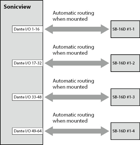
As a result, the preamps (Analog GAIN, PAD ON/OFF, Phantom ON/OFF) of the corresponding SB-16D INPUT can be operated on the Home Screen and MODULE screen of the module that has Dante 1–64 inputs assigned.
|
Module that can operate SB-16D preamps |
Object of preamp operation on the Home Screen and MODULE screen of the module (at left) |
|
Module with Dante IN 1–16 assigned |
INPUT 1–16 of the mounted SB-16D 1st in the list |
|
Module with Dante IN 17–32 assigned |
INPUT 1–16 of the mounted SB-16D 2nd in the list |
|
Module with Dante IN 33–48 assigned |
INPUT 1–16 of the mounted SB-16D 3rd in the list |
|
Module with Dante IN 49–64 assigned |
INPUT 1–16 of the mounted SB-16D 4th in the list |
Procedures for connecting 4 SB-16D units by Dante when the sampling rate of this unit’s built-in Dante module is “96kHz”.
In this case, using Dante Controller is necessary.
When the “Sampling rate” Sync Clock is set to “96kHz” for the unit’s built-in Dante module, the unit’s built-in Dante I/O count becomes 32-in/32-out. For this reason, an IF-DA64 (Dante card) must be installed in a card slot in order to connect this unit by Dante with SB-16D input and output ports numbered 33 and higher. This explanation assumes that an IF-DA64 has been installed in SLOT 1. (See “Installing expansion cards (sold separately)”.)
1.If multiple SB-16D units are connected to the Dante network, set IDs that are not duplicated on them in advance in order to enable their identification. For details about ID setting procedures, see the SB-16D operation manual.
2.Follow the instructions in “Precautions when using an IF-DA64” to enable synchronization of the two Dante modules (built-in Dante and IF-DA64 Dante card) with this unit’s master clock.
3.Connect the following Dante ports to the same Dante network.
Dante ports built into this unit
Dante ports of IF-DA64 installed in this unit
Dante ports of 4 SB-16D units
When connecting multiple SB-16D units, connect them through a switching hub as shown below. In this case, use different switching hubs for Primary and Secondary.
.jpg)
4.Set the Dante routing control method.
Tap Menu Screen > Rear Panel Setup > Dante Setup to open the Dante SETUP screen and tap the I/O Device tab.
5.Set the AUTO ROUTING button to “ON”.
6.Following the procedures in “Mounting of devices connected to the Dante network”, mount 4 SB-16D units one at a time from the top in the Mounted Device list.
_Mountedx4_2xFs.jpg)
7.Use Dante Controller on the computer connected to the Dante network in step 3 to make the following connection routing settings.
Connect Dante I/O 1–16 of the IF-DA64 installed in this unit to Dante I/O 1–16 of the SB-16D mounted 3rd from the top
Connect Dante I/O 17–32 of the IF-DA64 installed in this unit to Dante I/O 1–16 of the SB-16D mounted 4th from the top
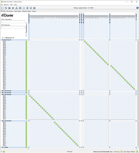
As a result, the Dante I/O ports of this unit’s built-in Dante, the IF-DA64 (Dante card) installed in this unit’s SLOT 1 and the 4 SB-16D units are routed by Dante as follows.
|
Dante I/O ports of this unit |
SB-16D Dante I/O ports |
|
Dante I/O 1–16 of this unit |
Dante I/O 1–16 of the SB-16D mounted 1st in the list |
|
Dante I/O 17–32 of this unit |
Dante I/O 1–16 of the SB-16D mounted 2nd in the list |
|
SLOT 1 I/O 1–16 of this unit |
Dante I/O 1–16 of the SB-16D mounted 3rd in the list |
|
SLOT 1 I/O 17–32 of this unit |
Dante I/O 1–16 of the SB-16D mounted 4th in the list |
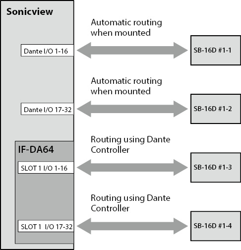
8.Acquire control privileges to enable operation of SB-16D units mounted 3rd and 4th from the top and routed through an IF-DA64 from the Home and MODULE screens of this unit.
Tap the “Pre Amp Control OFF” buttons for the 3rd and 4th devices to open the following confirmation message.
If control privileges for those SB-16D units have not been acquired by other devices:
The following message will be shown.
_Mountedx4_2xFs_EnablePreAmpCtrl.jpg)
Tapping the ENABLE button will set the control privileges and “Pre Amp Control” will be shown in the control privilege display area.
If control privileges for those SB-16D units have been acquired by other devices:
The following message will be shown.
_Mountedx4_2xFs_EnablePreAmpCtrl.jpg)
Tapping the REQUEST button and following the procedures from step 5 in “Mounting of devices connected to the Dante network” to acquire the control privileges will cause “Pre Amp Control” to be shown in the control privilege display area.
9.Conduct step 8 for the SB-16D units mounted 3rd and 4th in the list.
This will enable operation from this unit of SB-16D units mounted 3rd and 4th from the top and routed through an IF-DA64.
After completing these procedures, the preamps (Analog GAIN, PAD ON/OFF, Phantom ON/OFF) of the corresponding SB-16D units can be operated on the Home Screens and MODULE screens of the modules that have Dante 1–32 and SLOT 1–1 1–32 input ports assigned.
|
Module that can operate SB-16D preamps |
Object of preamp operation on the Home Screen and MODULE screen of the module (at left) |
|
Module with Dante IN 1–16 assigned |
INPUT 1–16 of the mounted SB-16D 1st in the list |
|
Module with Dante IN 17–32 assigned |
INPUT 1–16 of the mounted SB-16D 2nd in the list |
|
Module with SLOT 1 IN 1–16 assigned |
INPUT 1–16 of the mounted SB-16D 3rd in the list |
|
Module with SLOT 1 IN 17–32 assigned |
INPUT 1–16 of the mounted SB-16D 4th in the list |
ATTENTION
In these procedures, maintain the routing settings of the SB-16D units mounted 3rd and 4th from the top and the IF-DA64 (Dante card) as follows.
Connect Dante I/O 1–16 of the IF-DA64 installed in this unit to Dante I/O 1–16 of the SB-16D mounted 3rd from the top
Connect Dante I/O 17–32 of the IF-DA64 installed in this unit to Dante I/O 1–16 of the SB-16D mounted 4th from the top
If routings are changed from the above by Dante Controller, the preamp of an unintended SB-16D channel will be affected if a preamp is operated on this unit from the Home Screen or MODULE screen of a module with a corresponding SLOT input assigned.
Procedures to connect one SB-16D and a DA-6400* with an IF-DA64 (Dante card) installed to this unit by Dante
*In this example, connection is with Dante I/O 1–16 of a DA-6400 with an IF-DA64.
In this case, using Dante Controller is necessary.
1.If multiple SB-16D units are connected to the Dante network, set IDs that are not duplicated on them in advance in order to enable their identification. For details about ID setting procedures, see the SB-16D operation manual.
2.Connect the following Dante ports to the same Dante network.
Dante ports built into this unit
SB-16D Dante ports
Dante ports of the IF-DA64 installed in the DA-6400
When connecting 3 or more Dante devices, connect them through a switching hub as shown below. In this case, use different switching hubs for Primary and Secondary.
.jpg)
3.Set the Dante routing control method.
Tap Menu Screen > Rear Panel Setup > Dante Setup to open the Dante SETUP screen and tap the I/O Device tab.
4.Set the AUTO ROUTING button to “ON”.
5.Follow the procedures in “Mounting of devices connected to the Dante network”, and mount the SB-16D as the top item in the Mounted Device list.
6.Change the Dante routing control method.
7.Set the AUTO ROUTING button to “OFF”.
8.Use Dante Controller on the computer connected to the Dante network in step 2 to make the following and connection routing settings.
Dante I/O 17–32 of this unit
Dante I/O 1–16 of the IF-DA64 installed in the DA-6400
Example of Dante Controller display when routing settings have been made connecting this unit’s Dante I/O 17–32 and Dante I/O 1–16 of the IF-DA64 installed in the DA-6400
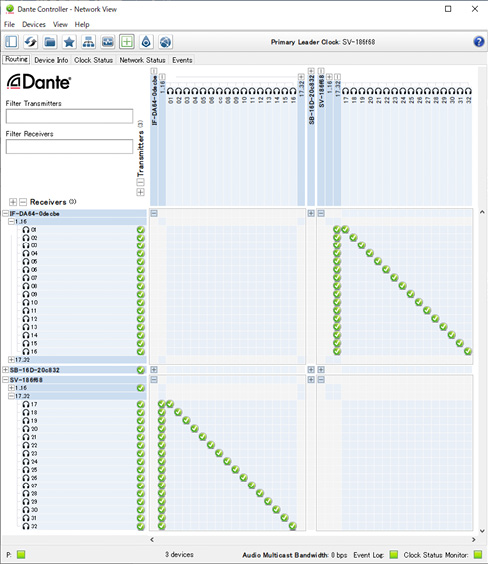
Through these procedures, the Dante I/O ports of this unit, the SB-16D and the IF-DA64 (Dante card) installed in the DA-6400 are routed by Dante as follows.
|
Dante I/O ports of this unit |
Dante I/O ports of external devices |
|
Dante I/O 1–16 of this unit |
Dante I/O 1–16 of the SB-16D mounted 1st in the list |
|
Dante I/O 17–32 of this unit |
Dante I/O 1–16 of the IF-DA64 installed in the DA-6400 |
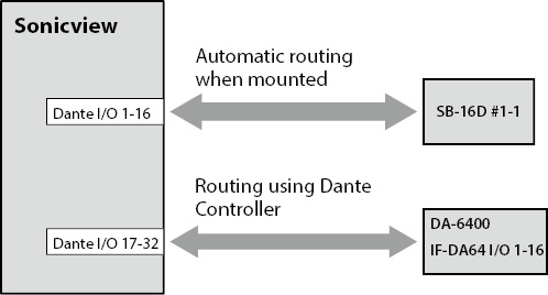
Example of Dante Controller display when the above routing settings have been made
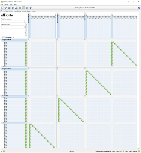
After completing these procedures, operation becomes possible for the preamps (Analog GAIN, PAD ON/OFF, Phantom ON/OFF) of the corresponding SB-16D INPUT on the Home Screen and MODULE screen of the module that has Dante IN 1–16 input ports assigned.
|
Module that can operate SB-16D preamps |
Object of preamp operation on the Home Screen and MODULE screen of the module (at left) |
|
Module with Dante IN 1–16 assigned |
INPUT 1–16 of the mounted SB-16D 1st in the list |
Dante is a transmission protocol developed by Audinate.
Using networks based on gigabit Ethernet standards, it enables multichannel (512 IN/512 OUT) transmission and high precision, for example.
Check the Audinate website for details about Dante.
In order to set up and use this unit, you must also set up the Ethernet network that it is connected to, a computer that runs Dante Controller and other devices that support Dante.
Dante controller is not necessary for use, however, when used with an SB-16D.
LAN cables used for connections
Use STP cables that are category 5e or higher.
Both crossover and straight cables can be used.
ATTENTION
This unit is not compatible with 100Mbps Ethernet switching hubs. Always use switching hubs that support Gigabit Ethernet.
NOTE
When the Dante Network Addressing setting is AUTO (DHCP), set the computer to set the IP address automatically.
When the Dante Network Addressing setting is STATIC, set the computer to match the Dante and network address.
Switched (daisy chain) connection
Dante devices can be daisy-chained when there are few connected devices and when not using a switching hub. Connect them as shown below.
Switched (daisy chain) connection example

NOTE
When using a switched (daisy chain) connection, connect to either the PRIMARY or SECONDARY connector.
If the number of connected devices increases, raising the latency setting will be necessary.
Redundant connection
For recording situations where retakes are not possible, including live performances, a connection set up like the following uses two completely independent primary and secondary networks.
Redundant connection example
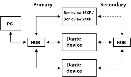
NOTE
Settings for switched (daisy chain) and redundant connections do not change automatically. Tap Menu Screen > Rear Panel Setup > Dante Setup to open the Dante SETUP Screen, or change the settings on the Dante Controller Network Config screen.
ATTENTION
The primary and secondary networks cannot be connected on the same LAN (VLAN).
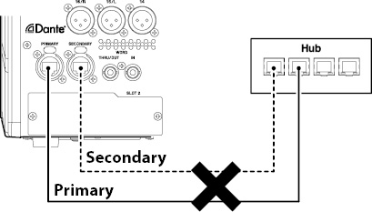
Dante Controller overview
This unit uses the Dante Controller application, which is available at the Audinate website, to connect with other devices that support Dante.
Download the latest version of the Dante Controller application and an operation manual from the Audinate website.
Audinate download page
https://www.audinate.com/products/software/dante-controller
Make at least the following settings using a computer that has Dante Controller installed.
Set the audio routing.
Adjust the sampling frequency and bit depth of each Dante device.
NOTE
Settings made using Dante Controller are stored in the built-in memory of each Dante device.
Unless settings are modified, connections will not change even if Dante Controller is quit or the computer is disconnected from the Dante network.
Audio routing settings
When Dante Controller is launched, the Network View screen shown below will open.
On this screen, you can set and monitor conditions related to the Dante network.
.jpg)
Receiving device name
This is the name of a receiving device on the Dante network.
Receiving device channels
These are the names of the channels of the receiving device on the Dante network.
Transmitting device name
This is the name of a transmitting device on the Dante network.
Transmitting device channels
These are the names of the channels of the transmitting device on the Dante network.
Audio routing
Route the audio channels of the transmitting and receiving devices that you want to connect here.
Click the intersection of the channels you want to connect on the matrix to connect them.
NOTE
While pressing the computer keyboard Ctrl key, click the “-” at the intersection of device names to connect all connectable channels at once.
Changing sampling frequencies and bit depths with Dante Controller
Double-click a device name on the Network View screen to open the Device View screen.
On this screen, you can set and monitor conditions related to devices on the Dante network.
Click the Device Config tab to open the page where you can change the sampling frequency, bit rate and other settings of the device selected in shown in the illustration below.
.jpg)
Device name
This is the name of the device that can have its settings changed in the current Device View.
Change device name
Edit the device name.
Sampling frequency
Set the sampling frequency.
NOTE
This can also be set on the unit.
Bit depth
Set the bit depth.
Latency setting
Set the latency.
Use the following guidelines to change the latency setting.
|
Selectable latency value |
Connected network setup guideline |
|
250usec |
The transmission route from the transmitting device to the receiving device passes through 1 gigabit switching hub. |
|
500usec |
The transmission route from the transmitting device to the receiving device passes through 5 gigabit switching hub. |
|
1msec |
The transmission route from the transmitting device to the receiving device passes through 10 gigabit switching hub. |
|
2msec |
The transmission speed of the transmitting device is 100 Mbps. |
|
5msec |
Use this maximum selectable latency value when creating a large-scale network. |
ATTENTION
This unit is not compatible with 100Mbps Ethernet switching hubs. Always use switching hubs that are compatible with Gigabit Ethernet.
Changing the name of a device will clear audio routing settings. For this reason, we recommend changing device names to names that are easy to identify before setting audio routings.
Depending on network connection conditions, setting the latency to a value higher than the guideline might be necessary.
NOTE
This can also be set on the unit.
When using a switched (daisy chain) connection, which does not use a switching hub, set the latency according to the number of Dante devices that signals pass-through as shown below.
Switched (daisy chain) connection example
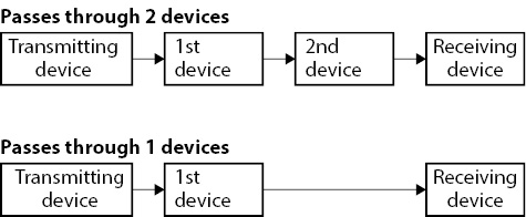
NOTE
The Dante module in this unit and IF-DA64 Dante cards (sold separately) have built-in switching hubs.
For this reason, when counting Dante devices, count this unit and IF-DA64 cards as two devices each.
Make settings and view information for expansion cards installed in SLOT 1 and SLOT 2 on this screen.
Tap Menu Screen > Rear Panel Setup > Slot Setup to open this screen.
.jpg)
SLOT 1
This shows the name of the expansion card installed in SLOT 1 on the rear panel.
SLOT 2
This shows the name of the expansion card installed in SLOT 2 on the rear panel.
SLOT 1 parameters
This shows the parameters of the expansion card installed in SLOT 1 on the rear panel.
SLOT 2 parameters
This shows the parameters of the expansion card installed in SLOT 2 on the rear panel.
NOTE
“No Card” will appear if no card has been installed in SLOT 1 or SLOT 2.
When an IF-DA64 (Dante) card is installed
.jpg)
STATUS display area
This shows the operation status of the installed IF-DA64.
|
STATUS |
Meaning |
|
Available |
The installed IF-DA64 is operating normally. |
|
Unavailable |
The installed IF-DA64 is not operating normally. |
Precautions when using an IF-DA64
The Dante module built into this unit, an IF-DA64 Dante card installed in a SLOT and the unit’s master clock must be synchronized. Do this as follows.
When the unit’s master clock is not Dante (INT, WORD, etc.)
Use Dante Controller to set the Sync to External setting to “ON” for both the built-in Dante module and the IF-DA64.
Use Dante Controller to set the Preferred Leader setting to “ON” for either one of them. (We recommend using the built-in Dante module.)
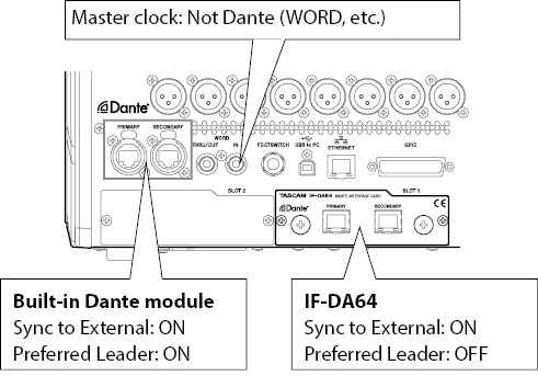
When the unit’s master clock is Dante
Use Dante Controller to set the Sync to External setting to “ON” for the IF-DA64.
Use Dante Controller to set the Preferred Leader setting to “ON” for a Dante module other than an IF-DA64. (We recommend using the built-in Dante module.)
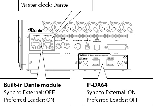
When an IF-AE16 (AES/EBU) card is installed
.jpg)
SRC ON/OFF buttons
These turn the SRC (sample rate converter) ON (default) and OFF for each signal line.
The selected buttons will be highlighted.
NOTE
SRC cannot be set to ON for the signal line selected as the master clock. For this reason, the signal line selected as the master clock will be shown as follows.
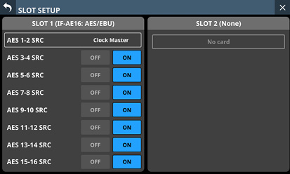
When an IF-MA64/EX or IF-MA64/BN (MADI) card is installed
.jpg)
MADI INPUT STATUS
This shows the channel mode/frame frequency of the MADI input signal.
“No signal” will appear if there is no input signal.
MADI INPUT FRAME
This shows the MADI input signal frame type (48K Frame/96K Frame).
“No signal” will appear if there is no input signal.
MADI INPUT SELECT buttons (IF-MA64/EX only)
Set the input connector used.
Options: COAXIAL, OPTICAL (default)
The selected button will be highlighted.
MADI OUTPUT CH MODE buttons
Set the output channel mode.
Options: 56ch/28ch, 64ch/32ch (default)
The selected button will be highlighted.
NOTE
Left of /: 1×Fs channel mode
Right of /: 2×Fs channel mode
2×Fs MADI OUTPUT FRAME buttons
These set the MADI output signal frame type when the unit's sampling frequency is 96 kHz.
Options: 48K Feame, 96K Frame (default)
The selected button will be highlighted.
ATTENTION
A MADI signal with a 96kHz sampling frequency and 48K Frame type cannot be distinguished from a MADI signal with a 48kHz sampling frequency.
For this reason, a 48K Frame MADI input signal that does not match the sampling frequency of the receiving device cannot be received as proper audio data.
When using a 48K Frame MADI signal, always match the sampling frequencies of the signal sending and receiving devices.
NOTE
The signal from the IF-MA64/EX MADI COAXIAL IN connector is output through its MADI COAXIAL THRU connector whether the unit is on or off.
When the unit is turned on/off, however, the signal output from the MADI COAXIAL THRU connector will be momentarily disrupted.
For this reason, time turning the unit on/off carefully when the signal output from the MADI COAXIAL THRU connector is being used by a connected device.
MADI COAXIAL EQUALIZER buttons
Set the equalizer for MADI COAXIAL input signals.
When an IF-MA64/EX or IF-MA64/BN is connected and a low-voltage MADI COAXIAL signal source or long BNC cable is being used, proper reception is not possible sometimes.
In this case, try setting MADI COAXIAL EQUALIZER to OFF.
Options: OFF, ON (default)
The selected button will be highlighted.
When an IF-AN16/OUT (analog output) card is installed
.jpg)
OUTPUT ATTENUATOR knobs
These adjust the output levels.
Range: −14.0 dB – 0.0 dB (default)
When the selection frame is shown, use the corresponding LCD knobs to adjust the values.
NOTE
The IF-AN16/OUT will always operate at 96 kHz even when synchronized to a master clock that is 48 kHz.
When an IF-MTR32 (multitrack recording) card is installed
.jpg)
SLOT SETUP screen when 2 IF-MTR32 cards installed
Recorder/Player: MTR
Tap this area to open the MULTI TRACK RECORDER Screen. (See “MULTI TRACK RECORDER Screen”.)
ATTENTION
Only one IF-MTR32 card can be used at a time.
If two IF-MTR32 cards are installed, only the one in SLOT 1 can be used. In this case, “Unavailable” will appear in the SLOT 2 area on the SLOT SETUP Screen.
When an IF-ST2110 (ST 2110) card is installed
.jpg)
SLOT SETUP screen when 2 IF-ST2110 cards installed
ST 2110 CONFIG
Tap this area to open the ST2110 SETUP Screen. (See “13 - IF-ST2110 expansion cards”.)
ATTENTION
Only one IF-ST2110 card can be used at a time.
If two IF-ST2110 cards are installed, only the one in SLOT 1 can be used. In this case, “Unavailable” will appear in the SLOT 2 area on the SLOT SETUP Screen.
Use this screen to set the display modes and display labels for port labels (input and output connector names) and module labels that are shown in various places.
Tap Menu Screen > Mixer Setup > Label Setup to open this screen. This screen can also be opened by tapping the ![]() icon in the LABEL setting area of the MODULE (INPUT) Screen or MODULE (OUTPUT) Screen.
icon in the LABEL setting area of the MODULE (INPUT) Screen or MODULE (OUTPUT) Screen.
NOTE
The settings on this screen are subject to snapshot storing and recall. Moreover, the corresponding PARAMETER SAFE page setting group is “LABEL / COLOR / ICON”. (See “PARAMETER SAFE page”.)
Use this screen to set the display modes for the port labels (input and output connector names) and module labels that are shown in various places.
.jpg)
PORT LABEL display mode setting buttons
Tap these buttons to set the display mode for the port labels (input and output connector names) as shown below.
The selected button will be highlighted.
|
Button |
Meaning |
|
USER (default) |
The USER PORT LABEL (port name set by user) is shown. If the USER PORT LABEL is undefined, the FIXED PORT LABEL will be shown. |
|
FIXED |
The predetermined FIXED PORT LABEL will be shown for each port (for example, “ANALOG 1” or “Dante 1”). |
See “Where the PORT LABEL display mode setting is applied” for details about where this setting is applied.
MODULE LABEL display mode setting buttons
Tap these buttons to set the MODULE LABEL display mode as shown below.
The selected button will be highlighted.
|
Button |
Meaning |
|
USER |
The USER MODULE LABEL (module name set by user) is shown. If the USER MODULE LABEL is undefined, the FIXED MODULE LABEL will be shown. |
|
FIXED |
The FIXED MODULE LABEL will be shown (predetermined names for each module, for example, “CH 1” and “MIX 1”). |
|
PORT LABEL |
The port name assigned to the corresponding module will be shown using the mode selected with the PORT LABEL display mode setting buttons ( |
The default Sub MODULE LABEL display mode is FIXED.
The default Main MODULE LABEL display mode is USER.
For details about where the settings are applied, see “Where the Sub MODULE LABEL display mode setting is applied” and “Where the Main MODULE LABEL display mode setting is applied”.
Home screen appearance example
This sample image is an example of the appearance on the Home Screen in accordance with the PORT LABEL display mode setting button () and MODULE LABEL display mode setting button ().
Where the PORT LABEL display mode setting is applied
On the Home Screen (names of input and output ports at the top)
Where the displayed content changes according to the display mode setting of the MODULE LABEL (only when the MODULE LABEL display mode is “PORT LABEL”)
NOTE
When stereo-linked but the input PORT LABEL area only has space for one channel, the input PORT LABEL for the L channel will be shown.
Multiple output ports can be selected, but if there is no area to show multiple output port labels, the PORT LABEL for the output port selected for SELECT PORT LABEL on the MODULE (OUTPUT) Screen will be shown (“ SELECT PORT LABEL button”). If nothing has been selected for the SELECT PORT LABEL mode, the PORT LABEL for the output port shown at the top left of the MODULE (OUTPUT) Screen will be shown.
Where the Sub MODULE LABEL display mode setting is applied
Channel screens (1st line from top)
Home screen (MODULE LABEL area top row)
DCA/Mute Group SETUP Screen (top row of each module button)
KEY IN SOURCE SELECT Screen (top row of each module button)
TALKBACK page (top row of bus name buttons)
TALKBACK page (top row of bus name buttons in SELECTED ASSIGN window)
TALKBACK page (top row of bus name buttons in TALKBACK KEY ASSIGN window)
All pages of MIXER CONFIG Screen (top row of module name buttons)
Custom Layer SETUP page (top row of module name buttons)
SENDS ON FADER Screen (top row of bus selection buttons)
Where the Main MODULE LABEL display mode setting is applied
Channel screens (2nd line from top)
Channel screens (“SEND to bus name” area when in Sends On Fader mode)
Channel screens (bus name area when in GEQ FADER Ctrl mode)
Home screen (MODULE LABEL area bottom row)
Home Screen (SEND area bus name)
Home Screen (bus selection buttons in the selection window shown when the ![]() button is tapped)
button is tapped)
MODULE Screen (USER MODULE LABEL display)
MODULE (COMP) Screen (KEY IN SOURCE button)
MODULE (DUCKER) Screen (KEY IN SOURCE button)
LIBRARY Screens for Module/GATE/EQ/COMP/GEQ (USER MODULE LABEL display)
MODULE (SEND/PAN) Screen (bus name area)
DCA/Mute Group SETUP Screen (bottom row of each module button)
KEY IN SOURCE SELECT Screen (bottom row of each module button)
All pages of METER Screen
All pages of SEND OVERVIEW Screen (send source module names)
TALKBACK page (bottom row of bus name buttons)
TALKBACK page (bottom row of bus name buttons in SELECTED ASSIGN window)
TALKBACK page (bottom row of bus name buttons in TALKBACK KEY ASSIGN window)
All pages of MIXER CONFIG Screen (bottom row of module name buttons)
Custom Layer SETUP page (bottom row of module name buttons)
SENDS ON FADER Screen (bottom row of bus selection buttons)
ST2110 SETUP Screen HOME (Source/Destination) page (MODULE column on Source Information window)
NOTE
If the MODULE LABEL display mode is set to “PORT LABEL”, the modules below that are not assigned to input and output ports will be shown the same as when the MODULE LABEL display mode setting is “USER”.
FX RTN 1–4 modules
DCA 1–8 module
This screen shows all the display labels for modules used in other places in a list and enables editing them.
.jpg)
Module group page switches
This shows the names of module group pages.
Tap a page name to switch to the page with the corresponding module group.
The name of the selected page will be highlighted.
Module buttons
These buttons show the FIXED MODULE LABEL in the upper line and the USER MODULE LABEL in the lower line. If the USER MODULE LABEL is undefined, the FIXED MODULE LABEL will be shown.
Tap one of these buttons to open the MODULE LABEL Screen where the USER MODULE LABEL can be edited for that module. (See “MODULE LABEL page”.)
This screen shows all the user port labels for input ports used in other places in a list and enables editing them.
.jpg)
Input port group page switches
These show the names of input port group pages.
Tap a page name to switch to the page with the corresponding input port group.
The name of the selected page will be highlighted.
Input port selection buttons
These buttons show the FIXED PORT LABEL in the upper line and the USER PORT LABEL in the lower line. If the USER PORT LABEL is undefined, the FIXED PORT LABEL will be shown.
Tap one of these buttons to open the USER LABEL (INPUT PORT) Screen where the USER PORT LABEL can be edited for that input port. (See “USER LABEL (INPUT PORT / OUTPUT PORT) Screen”.)
Scrollbar
These appear when all selectable options cannot be shown on the display at the same time.
Drag the display to scroll the screen. The screen can also be scrolled by swiping up and down on the input port selection button area () area.
Scroll knob
This appears highlighted when all selectable options cannot be shown on the display at the same time.
This icon shows that LCD knob 8 (lit light blue) can be used to scroll.
This screen shows all the user port labels for output ports used in other places in a list and enables editing them.
.jpg)
Output port group page switches
These show the names of output port group pages.
Tap a page name to switch to the page with the corresponding output port group.
The name of the selected page will be highlighted.
Output port selection buttons
These buttons show the FIXED PORT LABEL in the upper line and the USER PORT LABEL in the lower line. If the USER PORT LABEL is undefined, the FIXED PORT LABEL will be shown.
Tap one of these buttons to open the USER LABEL (OUTPUT PORT) Screen where the USER PORT LABEL can be edited for that output port. (See “USER LABEL (INPUT PORT / OUTPUT PORT) Screen”.)
Scrollbar
These appear when all selectable options cannot be shown on the display at the same time.
Drag the display to scroll the screen. The screen can also be scrolled by swiping up and down on the output port selection button area () area.
Scroll knob
This appears highlighted when all selectable options cannot be shown on the display at the same time.
This icon shows that LCD knob 8 (lit light blue) can be used to scroll.
USER LABEL (INPUT PORT / OUTPUT PORT) Screen
Use this screen to add and edit user port labels for input and output ports.
.jpg)
.jpg)
NOTE
User port labels are not set by default.
User port labels can have up to 8 characters.
![]() /
/ ![]() buttons
buttons
Tap these buttons to move left and right between the input/output ports shown for editing in their order on the input port group page of the INPUT PORT LABEL screen or the output port group page of the OUTPUT PORT LABEL screen.
FIXED PORT LABEL
This shows the FIXED PORT LABEL.
USER PORT LABEL
This shows the set USER PORT LABEL.
If the USER PORT LABEL is undefined, the FIXED PORT LABEL will be shown.
Keyboard input area
This shows the USER PORT LABEL being edited. Use the keyboard and buttons on this screen or a USB keyboard connected to the top panel USB port to edit the characters shown.
The combination of characters input can be changed depending on the status of the Caps lock and Shift keyboard buttons. See “Changing the keyboard keys” for details about changing the keyboard.
ATTENTION
The following symbols and punctuation marks cannot be input.
¥ / : * ? " < > |
Use this screen to make network settings primarily for the purpose of remote control of this unit using the dedicated TASCAM Sonicview Control application.
For details about the TASCAM Sonicview Control application, see its manual.
TASCAM Sonicview Control and its application manual can be downloaded from the TASCAM website.
Sonicview 16XP
https://tascam.com/us/product/sonicview_16xp/support
Sonicview 24XP
https://tascam.com/us/product/sonicview_24xp/support
Tap Menu Screen > Rear Panel Setup > Network Setup to open this screen.
.jpg)
Network status
This shows the network status of the unit.
|
Item |
Content |
|
MAC Address |
This shows the unit's MAC address. |
|
IP Address |
This shows the unit's IP address. |
IP SETUP
Set the IP address setting mode.
Options: AUTO (default), STATIC
IP Address/Subnet Mask/Default Gateway
This shows the IP Address, Subnet Mask and Default Gateway of the unit when IP SETUP is “STATIC”.
default: 0.0.0.0
This will be gray when IP SETUP is “AUTO”.
Tap the address fields to open the IP Address, Subnet Mask and Default Gateway screens.
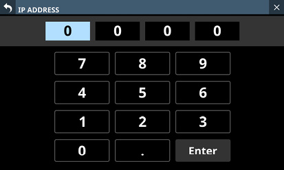
IP ADDRESS setting screen
See “IP Address/Subnet Mask/Default Gateway setting procedures” for details about how to use these setting screens.
Password
Set the password to use when connecting to this unit through a network.
Tap the Change button to open the Change password screen.
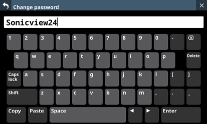
The password can have up to 16 characters.
|
Model |
Default password |
|
Sonicview 16XP |
Sonicview16 |
|
Sonicview 24XP |
Sonicview24 |
The combination of characters input can be changed depending on the status of the Caps lock and Shift keyboard buttons on the Change password screen. See “Changing the keyboard keys” for details about changing the keyboard.
ATTENTION
The following symbols and punctuation marks cannot be input.
¥ / : * ? " < > |
NOTE
A USB keyboard that is connected to the top panel USB port can also be used to input and edit characters.
Machine Name
The name of the unit on the network can be set so remote applications can distinguish it from other Sonicview units when multiple ones are on the network.
Tap this area to open the Machine name screen.
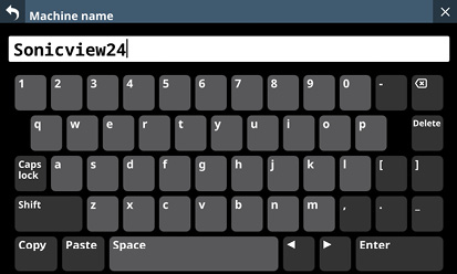
The machine name can have up to 16 characters.
|
Model |
Default machine name |
|
Sonicview 16XP |
Sonicview16 |
|
Sonicview 24XP |
Sonicview24 |
The combination of characters input can be changed depending on the status of the Caps lock and Shift keyboard buttons on the Machine name screen. See “Changing the keyboard keys” for details about changing the keyboard.
ATTENTION
The following symbols and punctuation marks cannot be input.
¥ / : * ? " < > |
NOTE
A USB keyboard that is connected to the top panel USB port can also be used to input and edit characters.
IP Address/Subnet Mask/Default Gateway setting procedures
The IP address is set to “192.168.1.1” as an example in this explanation.
1.Tap the IP Address, Subnet Mask and Default Gateway fields to open their setting screens.
2.Tap the number buttons to input setting values.
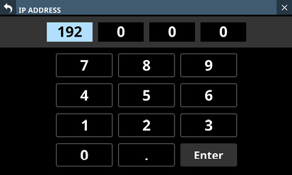
3.Tap “ . ” to move the cursor to the next field.
To change a setting, tap it to move the cursor to that field.
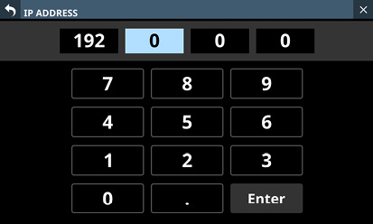
4.Repeat steps 2–3 as necessary to input setting values in each field.
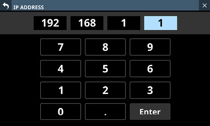
5.Tap the Enter button to confirm the input and return to the Network Setup Screen.
Changed settings will be reflected in the IP Address, Subnet Mask and Default Gateway fields of the Network Setup Screen.
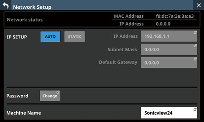
NOTE
Each input field has three digits. When inputting values with less than three digits, inputting “0” first is not necessary.
After this screen opens, the first field will be highlighted.
When a field is highlighted, tapping a number button will input that number, replacing the value previously in the field. After this, input numbers as on a calculator.
If a fourth digit is entered, the first digit entered will be removed. For example, if “1234” was entered, “1” will be removed.
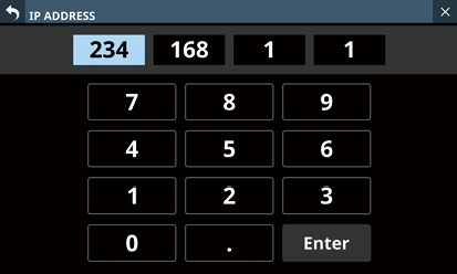
The settings of the unit are saved to the internal memory at least once every minute.
To be certain that the unit settings are saved in the internal memory before turning the power off, use the Save Current Settings function explained below.
NOTE
After saving All System Data or storing snapshot, EQ and other library settings data, settings have already been output to the memory, so these operations are not necessary before turning the power off.
1.Press the MENU key to open the Menu Screen.
2.On the Menu Screen, show the Save Current Settings item.
3.Tap the Save Current Settings item to open a saving confirmation message to the right of the menu list.
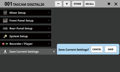
4.Tap the SAVE button to save the unit’s settings to its internal memory.
The message shown below will appear while saving.
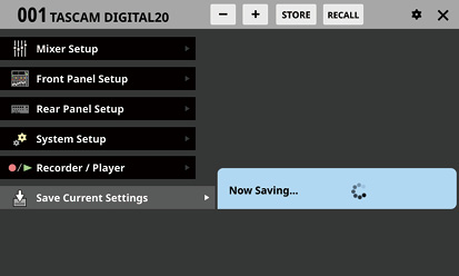
“Saved.” will momentarily appear after saving completes and then this message will disappear.
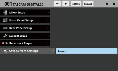
This chapter explains mixer input and output routing.
Use the following screen for input routing.
CH 1–40/ST IN 1–2 MODULE (OVERVIEW) Screens
Tap the MODULE LABEL area of a module on the Home Screen to open this screen.
_CH1_No(2024).jpg)
CH 1–40 modules
_ST-IN_No(2024).jpg)
ST IN 1–2 modules
INPUT button
This shows the name of the input source assigned to the selected module.
The second line shows an abbreviation of the FIXED PORT LABEL.
The third line shows the USER PORT LABEL.
If the USER PORT LABEL is undefined, the FIXED PORT LABEL will be shown.
If the module is stereo, the FIXED PORT LABEL for the input sources will appear split left and right and abbreviated as follows.
|
Module name shown |
Stereo module name shown |
|
ANALOG |
AN |
|
Dante |
DA |
|
SLOT 1 |
S1 |
|
SLOT 2 |
S2 |
|
USB IN |
USB |
|
ST IN 1 |
ST1 |
|
ST IN 2 |
ST2 |
|
PLAYER |
PL |
|
SB-16D |
SB |
![]()
If Dante ports that have mounted SB-16Ds assigned are selected, they will be shown as follows.
2nd line: DA port number
3rd line: #[ID] port number
4th line: USER PORT LABEL or SB #[ID] port number (if the USER PORT LABEL is undefined)
![]()
If it is a virtually-mounted SB-16D, ![]() will appear.
will appear.
![]()
Tap this button to open the INPUT SOURCE SELECT Screen where input sources can be selected. (See “INPUT SOURCE SELECT screen”.)
CH 1–40/ST IN 1–2 MODULE (INPUT) Screens
Tap the INPUT area on the Home Screen of a CH 1–40/ST IN 1–2 module when the selection frame is shown to open this screen.
_CH1_No(2025).jpg)
CH 1–40 modules
_ST-IN_No(2025).jpg)
ST IN 1–2 modules
This button locks/unlocks routing setting change operations for the unit. This is always locked at the time of start up.
When set to “LOCK”, tapping the OSC button () will not change settings. In addition, the BATCH SETUP button cannot be operated. However, tapping the INPUT SOURCE button and switching to the INPUT SOURCE SELECT Screen is possible.
When set to “LOCK”, tap this button to open a confirmation message. Tap the UNLOCK button to close the message and set it to “UNLOCK”. Tapping the CANCEL button on the confirmation message will close it and maintain the locked state.
_pop_Unlock-Routing.jpg)
Tap this button when set to “UNLOCK” to switch it to “LOCK”.
NOTE
The LOCK/UNLOCK button () setting is shared by the following routing setting screens.
MODULE (INPUT) Screen
MODULE (OUTPUT) Screen
INPUT SOURCE SELECT Screen
OUTPUT PORT SELECT Screen
DIRECT OUT PORT SELECT Screen
INSERT SEND PORT SELECT Screen
INSERT RETURN PORT SELECT Screen
TALKBACK INPUT SELECT Screen
TALKBACK EXT1 DIRECT OUT PORT SELECT Screen
TALKBACK EXT2 DIRECT OUT PORT SELECT Screen
Return TALKBACK EXT DIRECT OUT PORT SELECT Screen
MONITOR 1 DIRECT OUT PORT SELECT Screen
MONITOR 2 DIRECT OUT PORT SELECT Screen
MONITOR 2 OUTPUT PORT SELECT Screen
Solo DIRECT OUT PORT SELECT Screen
Routing Screen
INPUT SOURCE buttons
These buttons show the names of the currently selected input sources.
The first line shows an abbreviation of the FIXED PORT LABEL.
The second line shows the USER PORT LABEL.
If the USER PORT LABEL is undefined, the FIXED PORT LABEL will be shown.
Tap this button to open the INPUT SOURCE SELECT Screen. (See “INPUT SOURCE SELECT screen”.)
Buttons for Dante ports that have mounted SB-16Ds assigned will be shown as follows.
1st line: DA port number
2nd line: SB #[ID] port number
3rd line: USER PORT LABEL or SB #[ID] port number (if the USER PORT LABEL is undefined)
![]()
Assigned buttons for Dante ports that have virtually-mounted SB-16Ds will be highlighted yellow.
![]()
NOTE
Input sources for multiple channels can also be set at the same time. (See “Setting inputs sources for multiple channels at the same time in batches”.)
OSC button
When the LOCK/UNLOCK button () is set to “UNLOCK”, tap this button to turn internal oscillator signal input on or off (default).
When turned on, the input for the selected module will switch to the signal from the internal oscillator. When on, this button will appear highlighted, and the INPUT SOURCE selection () button area will be dimmed.
When this is turned off, the input source selected for the selected module will be reactivated.
NOTE
To turn the internal oscillator on/off, adjust its level and make other settings for it, tap the ![]() icon above and to the right of the OSC button and switch to the SOLO/OSCILLATOR page of the TALKBACK / MONITOR / SOLO / OSC SETUP Screen. (See “Making solo and built-in oscillator settings”.)
icon above and to the right of the OSC button and switch to the SOLO/OSCILLATOR page of the TALKBACK / MONITOR / SOLO / OSC SETUP Screen. (See “Making solo and built-in oscillator settings”.)
Setting inputs sources for multiple channels at the same time in batches
1.When the LOCK/UNLOCK button () is set to “UNLOCK”, tap the BATCH SETUP button on the MODULE (INPUT) Screen to open a BATCH SETUP window where multiple input sources can be set at the same time.
_pop_BATCH-SETUP.jpg)
2.Swipe the options up and down to select the input sources and the modules they will be assigned to.
Selections can also be changed by turning the LCD Knobs 2–6 with the same colors.
3.Tap the APPLY button to open a setting confirmation window.
_pop_BATCH-SETUP_set.jpg)
4.Tap the OK button to set multiple input sources at the same time.
This will close the BATCH SETUP window, and the INPUT SOURCE selection button will show the selected input source.
NOTE
When the LOCK/UNLOCK button is set to “LOCK”, the BATCH SETUP button is disabled.
If routing operation is set to “LOCK” on another touchscreen while a multiple setting window is open, it will close automatically.
Direct out signal output routing
The CH 1–40 modules have direct out functions.
Set direct out signal output routing on the MODULE (OVERVIEW) Screen for CH 1–40 modules.
Tap the MODULE LABEL area of a module on the Home Screen to open this screen.
_CH1_No(2024).jpg)
CH 1–40 modules
DIRECT OUT button
Tap this button to turn DIRECT OUT ON (default) or OFF.
When ON, the signal will be output directly from this point, and this button and the DIRECT OUT TRIM knob will be highlighted.
NOTE
The DIRECT OUT POINT for CH 1–40 modules can also be changed as explained in “CH 1–40 CONFIG page”.
DIRECT OUT TRIM knob
Use this to adjust the DIRECT OUT output signal level.
Range: −20 dB – +20 dB (default: 0 dB)
Turn LCD knob 2/4/5/7 (lit blue) to adjust it.
NOTE
The knob used for this operation depends on DIRECT OUT POINT and DELAY POINT settings.
OUTPUT button
This shows the name of the output port that the DIRECT OUT signal is assigned to.
The second line shows an abbreviation of the FIXED PORT LABEL.
The third line shows the USER PORT LABEL.
If the USER PORT LABEL is undefined, the FIXED PORT LABEL will be shown.
If it has been assigned to multiple output ports, “…” will appear to the bottom right of the button.
If the module is stereo, the FIXED PORT LABEL for the output ports will appear split left and right and abbreviated as follows.
|
Module name shown |
Stereo module name shown |
|
ANALOG |
AN |
|
Dante |
DA |
|
SLOT 1 |
S1 |
|
SLOT 2 |
S2 |
|
USB OUT |
USB |
![]()
If Dante ports that have mounted SB-16Ds assigned are selected, they will be shown as follows.
2nd line: DA port number
3rd line: #[ID] port number
4th line: USER PORT LABEL or SB #[ID] port number (if the USER PORT LABEL is undefined)
![]()
If it is a virtually-mounted SB-16D, ![]() will appear.
will appear.
![]()
Tap this button to open the DIRECT OUT PORT SELECT Screen where DIRECT OUT output ports can be selected. (See “DIRECT OUT PORT SELECT screen”.)
Insert input and output routing
The CH 1–40, MIX 1–22 and MAIN L/R Master modules have insert functions.
Set insert input and output routing on the MODULE (OVERVIEW) Screen of these modules.
Tap the MODULE LABEL area of a module on the Home Screen to open this screen.
_CH1_No(2024).jpg)
CH 1–40 modules
_MIX1_No(2024).jpg)
MIX 1–22 modules
_MAIN-LR_No(2024).jpg)
MAIN L/R Master module
SEND button
This shows the name of the output port that the INSERT SEND signal is assigned to.
The second line shows an abbreviation of the FIXED PORT LABEL.
The third line shows the USER PORT LABEL.
If the USER PORT LABEL is undefined, the FIXED PORT LABEL will be shown.
If it has been assigned to multiple output ports, “…” will appear to the bottom right of the button.
If the module is stereo, the FIXED PORT LABEL for the output ports will appear split left and right and abbreviated as follows.
|
Module name shown |
Stereo module name shown |
|
ANALOG |
AN |
|
Dante |
DA |
|
SLOT 1 |
S1 |
|
SLOT 2 |
S2 |
|
USB OUT |
USB |
![]()
If Dante ports that have mounted SB-16Ds assigned are selected, they will be shown as follows.
2nd line: DA port number
3rd line: #[ID] port number
4th line: USER PORT LABEL or SB #[ID] port number (if the USER PORT LABEL is undefined)
![]()
If it is a virtually-mounted SB-16D, ![]() will appear.
will appear.
![]()
Tap this button to open the INSERT SEND PORT SELECT Screen where INSERT SEND signal output ports can be selected. (See “INSERT SEND PORT SELECT screen”.)
INSERT button
Tap this button to turn INSERT ON or OFF (default).
When this is ON, the button will appear highlighted.
RETURN button
This shows the name of the input port that is assigned for the INSERT RETURN signal.
The second line shows an abbreviation of the FIXED PORT LABEL.
The third line shows the USER PORT LABEL.
If the USER PORT LABEL is undefined, the FIXED PORT LABEL will be shown.
If the module is stereo, the FIXED PORT LABEL for the input ports will appear split left and right and abbreviated as follows.
|
Module name shown |
Stereo module name shown |
|
ANALOG |
AN |
|
Dante |
DA |
|
SLOT 1 |
S1 |
|
SLOT 2 |
S2 |
|
USB IN |
USB |
|
ST IN 1 |
ST1 |
|
ST IN 2 |
ST2 |
|
PLAYER |
PL |
|
SB-16D |
SB |
![]()
If Dante ports that have mounted SB-16Ds assigned are selected, they will be shown as follows.
2nd line: DA port number
3rd line: #[ID] port number
4th line: USER PORT LABEL or SB #[ID] port number (if the USER PORT LABEL is undefined)
![]()
If it is a virtually-mounted SB-16D, ![]() will appear.
will appear.
![]()
Tap this button to open the INSERT RETURN PORT SELECT Screen where INSERT RETURN signal input ports can be selected. (See “INSERT RETURN PORT SELECT screen”.)
Use the following screens for output routing.
MIX 1–22 and MAIN L/R Master MODULE (OVERVIEW) Screens
Tap the MODULE LABEL area of a module on the Home Screen to open this screen.
_MIX1_No(2024).jpg)
MIX 1–22 modules
_MAIN-LR_No(2024).jpg)
MAIN L/R Master module
OUTPUT button
This shows the name of the output port that the output signal of the selected module is assigned to.
The second line shows an abbreviation of the FIXED PORT LABEL.
The third line shows the USER PORT LABEL.
If the USER PORT LABEL is undefined, the FIXED PORT LABEL will be shown.
If it has been assigned to multiple output ports, “…” will appear to the bottom right of the button.
If the module is stereo, the FIXED PORT LABEL for the output ports will appear split left and right and abbreviated as follows.
|
Module name shown |
Stereo module name shown |
|
ANALOG |
AN |
|
Dante |
DA |
|
SLOT 1 |
S1 |
|
SLOT 2 |
S2 |
|
USB OUT |
USB |
![]()
If Dante ports that have mounted SB-16Ds assigned are selected, they will be shown as follows.
2nd line: DA port number
3rd line: #[ID] port number
4th line: USER PORT LABEL or SB #[ID] port number (if the USER PORT LABEL is undefined)
![]()
If it is a virtually-mounted SB-16D, ![]() will appear.
will appear.
![]()
Tap this button to open the OUTPUT PORT SELECT Screen where output ports can be selected. (See “OUTPUT PORT SELECT screen”.)
MIX 1–22 and MAIN L/R Master MODULE (OUTPUT) Screens
Tap the OUTPUT area at the top of the Home Screen of a MIX 1–22 or MAIN L/R Master module to open this screen.
_MIX1_No(2025).jpg)
MIX 1–22 modules
_MAIN-LR_No(2025).jpg)
MAIN L/R Master module
LOCK/UNLOCK button
This button locks/unlocks routing setting change operations for the unit. This is always locked at the time of start up.
When locked, operation of the BATCH SETUP button is not possible. However, tapping the OUTPUT PORT SELECT area () and switching to the OUTPUT PORT SELECT Screen is possible.
When set to “LOCK”, tap this button to open a confirmation message. Tap the UNLOCK button to close the message and set it to “UNLOCK”. Tapping the CANCEL button on the confirmation message will close it and maintain the locked state.
_pop_Unlock-Routing.jpg)
Tap this button when set to “UNLOCK” to switch it to “LOCK”.
NOTE
The LOCK/UNLOCK button () setting is shared by the following routing setting screens.
MODULE (INPUT) Screen
MODULE (OUTPUT) Screen
INPUT SOURCE SELECT Screen
OUTPUT PORT SELECT Screen
DIRECT OUT PORT SELECT Screen
INSERT SEND PORT SELECT Screen
INSERT RETURN PORT SELECT Screen
TALKBACK INPUT SELECT Screen
TALKBACK EXT1 DIRECT OUT PORT SELECT Screen
TALKBACK EXT2 DIRECT OUT PORT SELECT Screen
Return TALKBACK EXT DIRECT OUT PORT SELECT Screen
MONITOR 1 DIRECT OUT PORT SELECT Screen
MONITOR 2 DIRECT OUT PORT SELECT Screen
MONITOR 2 OUTPUT PORT SELECT Screen
Solo DIRECT OUT PORT SELECT Screen
Routing Screen
OUTPUT PORT SELECT area
This area shows the output port that the signal of the selected module is assigned to.
The first line shows an abbreviation of the FIXED PORT LABEL.
The second line shows the USER PORT LABEL.
If the USER PORT LABEL is undefined, the FIXED PORT LABEL will be shown.
Up to 32 ports can be shown for mono modules.
Up to 16 ports can be shown for each stereo module.
If the number of assigned output ports exceeds the above, “…” will be shown at the bottom right of that area.
Tap this area to open the OUTPUT PORT SELECT Screen that has the tapped output port. (See “OUTPUT PORT SELECT screen”.)
If Dante ports that have mounted SB-16Ds assigned are selected, they will be shown as follows.
1st line: DA port number
2nd line: SB #[ID] port number
3rd line: USER PORT LABEL or SB #[ID] port number (if the USER PORT LABEL is undefined)
![]()
Assigned buttons for Dante ports that have virtually-mounted SB-16Ds will be highlighted yellow.
![]()
NOTE
Output ports for multiple channels can also be set at the same time. (See “Setting output ports for multiple channels at the same time in batches”.)
Setting output ports for multiple channels at the same time in batches
1.When the LOCK/UNLOCK button () is set to “UNLOCK”, tap the BATCH SETUP button on the MODULE (OUTPUT) Screen to open a BATCH SETUP window where multiple output ports can be set at the same time.
_MIX1_pop_BATCH-SETUP.jpg)
2.Swipe the options up and down to select the output ports.
Selections can also be changed by turning the LCD Knobs 2–6 with the same colors.
3.Tap the APPLY button to open a setting confirmation window.
_MIX1_pop_BATCH-SETUP_set.jpg)
4.Tap the OK button to change multiple output ports at the same time.
This will close the BATCH SETUP window, and the OUTPUT PORT selection button will show the selected output port.
NOTE
When the LOCK/UNLOCK button is set to “LOCK”, the BATCH SETUP button is disabled.
If routing operation is set to “LOCK” on another touchscreen while a multiple setting window is open, it will close automatically.
Select input sources for CH 1–40 and ST IN 1–2 modules on this screen.
Tap the INPUT button on the MODULE (OVERVIEW) Screen or the Others button on the MODULE (INPUT) Screen of these modules to open this screen. (See “Input routing”.)
.jpg)
.jpg)
LOCK/UNLOCK button
This button locks/unlocks routing setting change operations for the unit. This is always locked at the time of start up.
When set to “LOCK”, tapping the input source selection button () will not change settings.
When set to “LOCK”, tap this button to open a confirmation message. Tap the UNLOCK button to close the message and set it to “UNLOCK”. Tapping the CANCEL button on the confirmation message will close it and maintain the locked state.
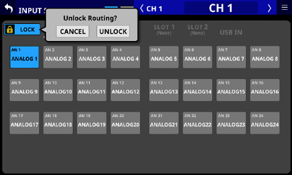
Tap this button when set to “UNLOCK” to switch it to “LOCK”.
NOTE
The LOCK/UNLOCK button () setting is shared by the following routing setting screens.
MODULE (INPUT) Screen
MODULE (OUTPUT) Screen
INPUT SOURCE SELECT Screen
OUTPUT PORT SELECT Screen
DIRECT OUT PORT SELECT Screen
INSERT SEND PORT SELECT Screen
INSERT RETURN PORT SELECT Screen
TALKBACK INPUT SELECT Screen
TALKBACK EXT1 DIRECT OUT PORT SELECT Screen
TALKBACK EXT2 DIRECT OUT PORT SELECT Screen
Return TALKBACK EXT DIRECT OUT PORT SELECT Screen
MONITOR 1 DIRECT OUT PORT SELECT Screen
MONITOR 2 DIRECT OUT PORT SELECT Screen
MONITOR 2 OUTPUT PORT SELECT Screen
Solo DIRECT OUT PORT SELECT Screen
Routing Screen
Input source group page switches
These show input source group page names.
Tap a page name to switch to the page with the corresponding input source group. The name of the selected page will be highlighted. An * will appear next to the name of the page that the selected input source is on.
|
Page name |
Contents |
|
ANALOG INPUT |
Select analog MIC/LINE input jacks on this page. |
|
ST IN Player |
Select the two pairs of ST IN jacks and the internal memory player. |
|
Dante |
Select the built-in Dante inputs. |
|
SLOT 1 |
Select the inputs of the expansion card installed in SLOT 1. |
|
SLOT 2 |
Select the inputs of the expansion card installed in SLOT 2. |
|
USB IN |
Select USB audio interface inputs. |
L/R selection buttons
These select whether to set the input ports of the left or right channels of stereo modules.
Tap these buttons to switch between left and right. The selected button will be highlighted.
Input source selection buttons
When the LOCK/UNLOCK button () is set to “UNLOCK”, tap these buttons to select input sources.
The selected button will be highlighted light blue.
Buttons that cannot be used will appear dark gray.
If a button that cannot be used is selected, it will appear dark blue.
The first line shows an abbreviation of the FIXED PORT LABEL.
The second line shows the USER PORT LABEL.
If the USER PORT LABEL is undefined, the FIXED PORT LABEL will be shown.
For stereo modules, “L” will be shown on the bottom left of the button selected for the left channel and “R” will be shown on the bottom right of the button selected for the right channel.
If Dante ports that have mounted SB-16Ds assigned are selected, they will be shown as follows.
1st line: DA port number
2nd line: SB #[ID] port number
3rd line: USER PORT LABEL or SB #[ID] port number (if the USER PORT LABEL is undefined)
![]()
If it is a virtually-mounted SB-16D, ![]() will appear.
will appear.
![]()
Assigned buttons for Dante ports that have virtually-mounted SB-16Ds will be highlighted yellow.
![]()
Scroll knob and scrollbar
These appear when all selectable options cannot be shown on the display at the same time.
Drag the display to scroll the screen. The screen can also be scrolled by swiping up and down on the input source selection button () area as well as by turning LCD knob 8.
![]() /
/ ![]() buttons
buttons
Tap these buttons to switch the INPUT SOURCE between INPUT A and INPUT B. (Default: ![]() )
)
Select output ports for CH 1–40 module DIRECT OUT signals on this screen.
Tap the OUTPUT button above the DIRECT OUT TRIM knob on the MODULE (OVERVIEW) Screen for CH 1–40 modules to open this screen. (See “Direct out signal output routing”.)
.jpg)
.jpg)
LOCK/UNLOCK button
This button locks/unlocks routing setting change operations for the unit. This is always locked at the time of start up.
When set to “LOCK”, tapping an output port selection button () will not change the setting.
When set to “LOCK”, tap this button to open a confirmation message. Tap the UNLOCK button to close the message and set it to “UNLOCK”. Tapping the CANCEL button on the confirmation message will close it and maintain the locked state.
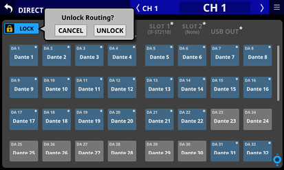
Tap this button when set to “UNLOCK” to switch it to “LOCK”.
NOTE
The LOCK/UNLOCK button () setting is shared by the following routing setting screens.
MODULE (INPUT) Screen
MODULE (OUTPUT) Screen
INPUT SOURCE SELECT Screen
OUTPUT PORT SELECT Screen
DIRECT OUT PORT SELECT Screen
INSERT SEND PORT SELECT Screen
INSERT RETURN PORT SELECT Screen
TALKBACK INPUT SELECT Screen
TALKBACK EXT1 DIRECT OUT PORT SELECT Screen
TALKBACK EXT2 DIRECT OUT PORT SELECT Screen
Return TALKBACK EXT DIRECT OUT PORT SELECT Screen
MONITOR 1 DIRECT OUT PORT SELECT Screen
MONITOR 2 DIRECT OUT PORT SELECT Screen
MONITOR 2 OUTPUT PORT SELECT Screen
Solo DIRECT OUT PORT SELECT Screen
Routing Screen
Output port group page switches
These show output port group page names.
Tap a page name to switch to the page with the corresponding output port group. The name of the selected page will be highlighted. An * will appear next to the name of the page that the selected output port is on.
|
Page name |
Contents |
|
ANALOG OUTPUT |
Select analog output ports. |
|
Dante |
Select built-in Dante output ports. |
|
SLOT 1 |
Select the output ports of the expansion card installed in SLOT 1. |
|
SLOT 2 |
Select the output ports of the expansion card installed in SLOT 2. |
|
USB OUT |
Select USB audio interface output ports. |
L/R selection buttons
These select whether to set the output ports of the left or right channels of stereo modules.
Tap these buttons to switch between left and right. The selected button will be highlighted.
Output port selection buttons
When the LOCK/UNLOCK button () is set to “UNLOCK”, tap these buttons to select output ports. The selected button will be highlighted light blue. Buttons that cannot be used will appear dark gray. If a button that cannot be used is selected, it will appear dark blue.
The first line shows an abbreviation of the FIXED PORT LABEL.
The second line shows the USER PORT LABEL.
If the USER PORT LABEL is undefined, the FIXED PORT LABEL will be shown.
For stereo modules, “L” will be shown to the bottom left of the button selected for the left channel and “R” will be shown to the bottom right of the button selected for the right channel.
If Dante ports that have mounted SB-16Ds assigned are selected, they will be shown as follows.
1st line: DA port number
2nd line: SB #[ID] port number
3rd line: USER PORT LABEL or SB #[ID] port number (if the USER PORT LABEL is undefined)
![]()
If it is a virtually-mounted SB-16D, ![]() will appear.
will appear.
![]()
Assigned buttons for Dante ports that have virtually-mounted SB-16Ds will be highlighted yellow.
![]()
An * will appear on the buttons of ports that are already assigned to other modules, and the buttons will appear grayish blue. Tap these buttons to open a setting confirmation window. Tap the OK button to change the setting and close the window. Tap the CANCEL button to close the window without changing the setting.
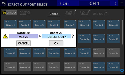
NOTE
The signal from a single module can be assigned to multiple output ports.
Scroll knob and scrollbar
These appear when all selectable options cannot be shown on the display at the same time.
Drag the display to scroll the screen. The screen can also be scrolled by swiping up and down on the output port selection button () area as well as by turning LCD knob 8.
INSERT SEND PORT SELECT screen
Set INSERT SEND signal output ports for CH 1–40, MIX 1–22 and MAIN L/R Master modules on this screen.
Tap the SEND button on the MODULE (OVERVIEW) Screen of these modules to open this screen. (See “Insert input and output routing”.)
.jpg)
.jpg)
LOCK/UNLOCK button
This button locks/unlocks routing setting change operations for the unit. This is always locked at the time of start up.
When set to “LOCK”, tapping an output port selection button () will not change the setting.
When set to “LOCK”, tap this button to open a confirmation message. Tap the UNLOCK button to close the message and set it to “UNLOCK”. Tapping the CANCEL button on the confirmation message will close it and maintain the locked state.
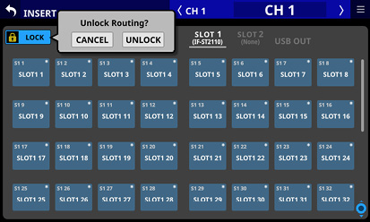
Tap this button when set to “UNLOCK” to switch it to “LOCK”.
NOTE
The LOCK/UNLOCK button () setting is shared by the following routing setting screens.
MODULE (INPUT) Screen
MODULE (OUTPUT) Screen
INPUT SOURCE SELECT Screen
OUTPUT PORT SELECT Screen
DIRECT OUT PORT SELECT Screen
INSERT SEND PORT SELECT Screen
INSERT RETURN PORT SELECT Screen
TALKBACK INPUT SELECT Screen
TALKBACK EXT1 DIRECT OUT PORT SELECT Screen
TALKBACK EXT2 DIRECT OUT PORT SELECT Screen
Return TALKBACK EXT DIRECT OUT PORT SELECT Screen
MONITOR 1 DIRECT OUT PORT SELECT Screen
MONITOR 2 DIRECT OUT PORT SELECT Screen
MONITOR 2 OUTPUT PORT SELECT Screen
Solo DIRECT OUT PORT SELECT Screen
Routing Screen
Output port group page switches
These show output port group page names.
Tap a page name to switch to the page with the corresponding output port group. The name of the selected page will be highlighted. An * will appear next to the name of the page that the selected output port is on.
|
Page name |
Contents |
|
ANALOG OUTPUT |
Select analog output ports. |
|
Dante |
Select built-in Dante output ports. |
|
SLOT 1 |
Select the output of the expansion card installed in SLOT 1. |
|
SLOT 2 |
Select the output of the expansion card installed in SLOT 2. |
|
USB OUT |
Select USB audio interface output ports. |
L/R selection buttons
These select whether to set the output ports of the left or right channels of stereo modules.
Tap these buttons to switch between left and right. The selected button will be highlighted.
Output port selection buttons
When the LOCK/UNLOCK button () is set to “UNLOCK”, tap these buttons to select output ports. The selected button will be highlighted light blue. Buttons that cannot be used will appear dark gray. If a button that cannot be used is selected, it will appear dark blue.
The first line shows an abbreviation of the FIXED PORT LABEL.
The second line shows the USER PORT LABEL.
If the USER PORT LABEL is undefined, the FIXED PORT LABEL will be shown.
For stereo modules, “L” will be shown to the bottom left of the button selected for the left channel and “R” will be shown to the bottom right of the button selected for the right channel.
If Dante ports that have mounted SB-16Ds assigned are selected, they will be shown as follows.
1st line: DA port number
2nd line: SB #[ID] port number
3rd line: USER PORT LABEL or SB #[ID] port number (if the USER PORT LABEL is undefined)
![]()
If it is a virtually-mounted SB-16D, ![]() will appear.
will appear.
![]()
Assigned buttons for Dante ports that have virtually-mounted SB-16Ds will be highlighted yellow.
![]()
An * will appear on the buttons of ports that are already assigned to other modules, and the buttons will appear grayish blue. Tap these buttons to open a setting confirmation window. Tap the OK button to change the setting and close the window. Tap the CANCEL button to close the window without changing the setting.
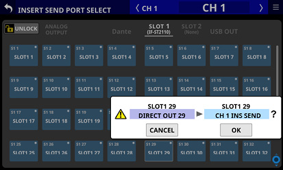
NOTE
The signal from a single module can be assigned to multiple output ports.
Scroll knob and scrollbar
These appear when all selectable options cannot be shown on the display at the same time.
Drag the display to scroll the screen. The screen can also be scrolled by swiping up and down on the output port selection button () area as well as by turning LCD knob 8.
INSERT RETURN PORT SELECT screen
Set INSERT RETURN signal input ports for CH 1–40, MIX 1–22 and MAIN L/R Master modules on this screen.
Tap the RETURN button on the MODULE (OVERVIEW) Screen of these modules to open this screen. (See “Insert input and output routing”.)
.jpg)
.jpg)
LOCK/UNLOCK button
This button locks/unlocks routing setting change operations for the unit. This is always locked at the time of start up.
When set to “LOCK”, tapping the input source selection button () will not change settings.
When set to “LOCK”, tap this button to open a confirmation message. Tap the UNLOCK button to close the message and set it to “UNLOCK”. Tapping the CANCEL button on the confirmation message will close it and maintain the locked state.
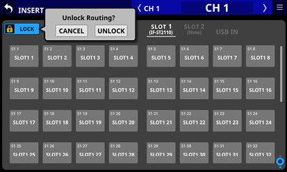
Tap this button when set to “UNLOCK” to switch it to “LOCK”.
NOTE
The LOCK/UNLOCK button () setting is shared by the following routing setting screens.
MODULE (INPUT) Screen
MODULE (OUTPUT) Screen
INPUT SOURCE SELECT Screen
OUTPUT PORT SELECT Screen
DIRECT OUT PORT SELECT Screen
INSERT SEND PORT SELECT Screen
INSERT RETURN PORT SELECT Screen
TALKBACK INPUT SELECT Screen
TALKBACK EXT1 DIRECT OUT PORT SELECT Screen
TALKBACK EXT2 DIRECT OUT PORT SELECT Screen
Return TALKBACK EXT DIRECT OUT PORT SELECT Screen
MONITOR 1 DIRECT OUT PORT SELECT Screen
MONITOR 2 DIRECT OUT PORT SELECT Screen
MONITOR 2 OUTPUT PORT SELECT Screen
Solo DIRECT OUT PORT SELECT Screen
Routing Screen
Input source group page switches
These show input source group page names.
Tap a page name to switch to the page with the corresponding input source group. The name of the selected page will be highlighted. An * will appear next to the name of the page that the selected input source is on.
|
Page name |
Contents |
|
ANALOG INPUT |
Select analog MIC/LINE input jacks on this page. |
|
ST IN Player |
Select the two pairs of ST IN jacks and the internal memory player. |
|
Dante |
Select the built-in Dante inputs. |
|
SLOT 1 |
Select the input ports of the expansion card installed in SLOT 1. |
|
SLOT 2 |
Select the input ports of the expansion card installed in SLOT 2. |
|
USB IN |
Select USB audio interface inputs. |
L/R selection buttons
These select whether to set the input ports of the left or right channels of stereo modules.
Tap these buttons to switch between left and right. The selected button will be highlighted.
Input source selection buttons
When the LOCK/UNLOCK button () is set to “UNLOCK”, tap these buttons to select input sources. The selected button will be highlighted light blue. Buttons that cannot be used will appear dark gray. If a button that cannot be used is selected, it will appear dark blue.
The first line shows an abbreviation of the FIXED PORT LABEL.
The second line shows the USER PORT LABEL.
If the USER PORT LABEL is undefined, the FIXED PORT LABEL will be shown.
For stereo modules, “L” will be shown to the bottom left of the button selected for the left channel and “R” will be shown to the bottom right of the button selected for the right channel.
If Dante ports that have mounted SB-16Ds assigned are selected, they will be shown as follows.
1st line: DA port number
2nd line: SB #[ID] port number
3rd line: USER PORT LABEL or SB #[ID] port number (if the USER PORT LABEL is undefined)
![]()
If it is a virtually-mounted SB-16D, ![]() will appear.
will appear.
![]()
Assigned buttons for Dante ports that have virtually-mounted SB-16Ds will be highlighted yellow.
![]()
If one of the following input ports that has an Analog GAIN setting is selected, corresponding parameters for that port will be set automatically to the line level standard settings as shown below.
Input ports
ANALOG INPUT
Built-in Dante port with SB-16D routing
Ports for SLOT that has IF-DA64 installed with SB-16D routing
Parameters that will be changed automatically
PAD: ON
Analog GAIN: 0
Phantom: OFF
NOTE
When the input port of an SB-16D is selected, if control privileges for the concerned SB-16D have not been acquired by this unit, the above parameters cannot be changed, so the following message will be shown on the rightmost touchscreen.
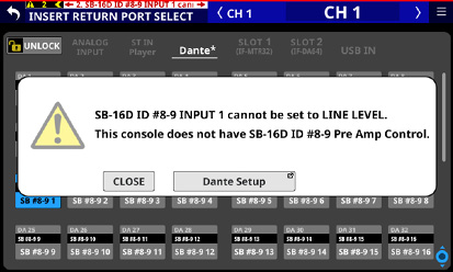
Scroll knob and scrollbar
These appear when all selectable options cannot be shown on the display at the same time.
Drag the display to scroll the screen. The screen can also be scrolled by swiping up and down on the input source selection button () area as well as by turning LCD knob 8.
Set output ports for MIX 1–22 and MAIN L/R Master modules on this screen.
Tap the OUTPUT button on the MODULE (OVERVIEW) Screen or the Others button on the MODULE (OUTPUT) Screen of these modules to open this screen. (See “Output routing”.)
.jpg)
.jpg)
LOCK/UNLOCK button
This button locks/unlocks routing setting change operations for the unit. This is always locked at the time of start up.
When set to “LOCK”, tapping an output port selection button () will not change the setting.
When set to “LOCK”, tap this button to open a confirmation message. Tap the UNLOCK button to close the message and set it to “UNLOCK”. Tapping the CANCEL button on the confirmation message will close it and maintain the locked state.
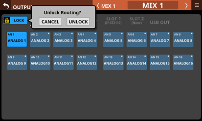
Tap this button when set to “UNLOCK” to switch it to “LOCK”.
NOTE
The LOCK/UNLOCK button () setting is shared by the following routing setting screens.
MODULE (INPUT) Screen
MODULE (OUTPUT) Screen
INPUT SOURCE SELECT Screen
OUTPUT PORT SELECT Screen
DIRECT OUT PORT SELECT Screen
INSERT SEND PORT SELECT Screen
INSERT RETURN PORT SELECT Screen
TALKBACK INPUT SELECT Screen
TALKBACK EXT1 DIRECT OUT PORT SELECT Screen
TALKBACK EXT2 DIRECT OUT PORT SELECT Screen
Return TALKBACK EXT DIRECT OUT PORT SELECT Screen
MONITOR 1 DIRECT OUT PORT SELECT Screen
MONITOR 2 DIRECT OUT PORT SELECT Screen
MONITOR 2 OUTPUT PORT SELECT Screen
Solo DIRECT OUT PORT SELECT Screen
Routing Screen
Output port group page switches
These show output port group page names.
Tap a page name to switch to the page with the corresponding output port group. The name of the selected page will be highlighted. An * will appear next to the name of the page that the selected output port is on.
|
Page name |
Contents |
|
ANALOG OUTPUT |
Select analog output ports. |
|
Dante |
Select built-in Dante output ports. |
|
SLOT 1 |
Select the output ports of the expansion card installed in SLOT 1. |
|
SLOT 2 |
Select the output ports of the expansion card installed in SLOT 2. |
|
USB OUT |
Select USB audio interface output ports. |
L/R selection buttons
These select whether to set the output ports of the left or right channels of stereo modules.
Tap these buttons to switch between left and right. The selected button will be highlighted.
Output port selection buttons
When the LOCK/UNLOCK button () is set to “UNLOCK”, tap these buttons to select output ports. The selected button will be highlighted light blue. Buttons that cannot be used will appear dark gray. If a button that cannot be used is selected, it will appear dark blue.
The first line shows an abbreviation of the FIXED PORT LABEL.
The second line shows the USER PORT LABEL.
If the USER PORT LABEL is undefined, the FIXED PORT LABEL will be shown.
For stereo modules, “L” will be shown to the bottom left of the button selected for the left channel and “R” will be shown to the bottom right of the button selected for the right channel.
If Dante ports that have mounted SB-16Ds assigned are selected, they will be shown as follows.
1st line: DA port number
2nd line: SB #[ID] port number
3rd line: USER PORT LABEL or SB #[ID] port number (if the USER PORT LABEL is undefined)
![]()
If it is a virtually-mounted SB-16D, ![]() will appear.
will appear.
![]()
Assigned buttons for Dante ports that have virtually-mounted SB-16Ds will be highlighted yellow.
![]()
An * will appear on the buttons of ports that are already assigned to other modules, and the buttons will appear grayish blue. Tap these buttons to open a setting confirmation window. Tap the OK button to change the setting and close the window. Tap the CANCEL button to close the window without changing the setting.
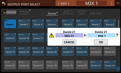
NOTE
The signal from a single module can be assigned to multiple output ports.
Scroll knob and scrollbar
These appear when all selectable options cannot be shown on the display at the same time.
Drag the display to scroll the screen. The screen can also be scrolled by swiping up and down on the output port selection button () area as well as by turning LCD knob 8.
Routing settings for the input/output ports and modules can be made on this screen.
Use the following procedures to open this screen.
Tap Menu screen > Mixer Setup menu > Routing
Tap the ROUTING button on the MODULE (INPUT) Screen
Tap the ROUTING button on the MODULE (OUTPUT) Screen
Selection buttons for each page are at the top of the Routing Screen.
.jpg)
LOCK/UNLOCK button
This button locks/unlocks routing setting change operations for the unit. This is always locked at the time of start up. (See “ LOCK/UNLOCK button”.)
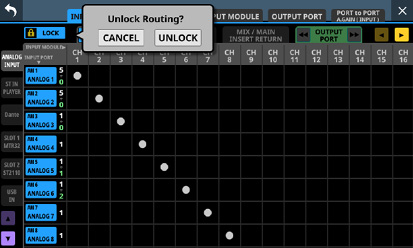
NOTE
The LOCK/UNLOCK button () setting is shared by the following routing setting screens.
MODULE (INPUT) Screen
MODULE (OUTPUT) Screen
INPUT SOURCE SELECT Screen
OUTPUT PORT SELECT Screen
DIRECT OUT PORT SELECT Screen
INSERT SEND PORT SELECT Screen
INSERT RETURN PORT SELECT Screen
TALKBACK INPUT SELECT Screen
TALKBACK EXT1 DIRECT OUT PORT SELECT Screen
TALKBACK EXT2 DIRECT OUT PORT SELECT Screen
Return TALKBACK EXT DIRECT OUT PORT SELECT Screen
MONITOR 1 DIRECT OUT PORT SELECT Screen
MONITOR 2 DIRECT OUT PORT SELECT Screen
MONITOR 2 OUTPUT PORT SELECT Screen
Solo DIRECT OUT PORT SELECT Screen
Routing Screen
Page selection buttons
Tap these buttons to switch between pages that show the input/output ports/modules desired for making routing settings.
The selected button will be highlighted.
|
Page button |
Use |
|
INPUT PORT |
Routing settings for input ports |
|
INPUT MODULE |
Routing settings from input module standpoints |
|
OUTPUT MODULE |
Routing settings from output modules |
|
OUTPUT PORT |
Routing settings from output port standpoints |
|
PORT to PORT A.GAIN (INPUT) |
Analog gain settings for input ports assigned to the PORT to PORT function (See “PORT to PORT A.GAIN (INPUT) page”.) |
PORT to PORT overview
The setting that directly connects an input port with an output port is called “PORT to PORT”.
PORT to PORT can be set for 24 channels.
1.Select “ INPUT PORT” from the Routing Screen page buttons ().
2.Select “OUTPUT PORT” from the INPUT PORT page INPUT MODULE selection buttons () to set it.
3.When the SELECT button () is lit, set the input port and set the output port in the Input Port Routing Setting area ().
.jpg)
On this screen, view and set routings from input port standpoints, considering “to where the input ports are assigned”.
.jpg)
CH MODULE Routing Screen
.jpg)
CH INSERT RETURN Routing Screen
.jpg)
MIX/MAIN INSERT RETURN Routing Screen
.jpg)
PORT to PORT Routing Screen
Input source group page selection buttons
These tab buttons select types of input sources for routing.
They can also be scrolled 4 lines at a time by tapping the ![]() and
and ![]() buttons or turning LCD knob 1.
buttons or turning LCD knob 1.
INPUT PORT display
This shows information about input ports.
The first line shows an abbreviation of the FIXED PORT LABEL.
The second line shows the USER PORT LABEL.
If the USER PORT LABEL is undefined, the FIXED PORT LABEL will be shown.
The numbers on the right show the number of modules assigned to that input port (white numbers) and the number of output ports assigned to the PORT to PORT function (yellow-green numbers).
Tap an INPUT PORT in this area to scroll the Input Port Routing Setting area () to a position that shows an assigned module.
INPUT MODULE selection buttons
These tab buttons select types of routing assignment destinations for input sources.
Tap the CH MODULE page ![]() or
or ![]() button to select whether to show settings for INPUT A or INPUT B.
button to select whether to show settings for INPUT A or INPUT B.
The output port type can be switched by tapping the OUTPUT PORT page ![]() and
and ![]() buttons.
buttons.
PORT to PORT function routings can be set on this screen.
8 items at a time can also be scrolled by tapping the ![]() and
and ![]() buttons or turning LCD knob 1.
buttons or turning LCD knob 1.
Input Port Routing Setting area
Set routings from input ports to output ports here.
Input routings can be changed by tapping the intersections of input and output ports.
An ![]() icon will appear at the intersection of the input and output ports. The
icon will appear at the intersection of the input and output ports. The ![]() icons can also be tapped to disconnect input routings.
icons can also be tapped to disconnect input routings.
SELECT button
This switches the operation mode used when a PORT to PORT input source button () is tapped.
If PORT to PORT input source buttons () are tapped when this is lit, settings can be made for the input ports of the corresponding items.
PORT to PORT numbers
This shows the numbers of the PORT to PORT function with 24 channels.
They can also be scrolled 4 lines at a time by tapping the ![]() and
and ![]() buttons or turning LCD knob 1.
buttons or turning LCD knob 1.
PORT to PORT input source buttons
These show the names of input sources assigned to the PORT to PORT function.
The first line shows an abbreviation of the FIXED PORT LABEL.
The second line shows the USER PORT LABEL.
If the USER PORT LABEL is undefined, the FIXED PORT LABEL will be shown.
The yellow-green numbers on the right show the number of output ports assigned to that input port.
Tapping these buttons when the SELECT button () is gray will scroll the Input Port Routing Setting area () to a position that shows a module with that input port assigned.
Tapping one of these buttons when the SELECT button () is lit will switch to the INPUT SOURCE SELECT Screen where the tapped input port is. (See “INPUT SOURCE SELECT screen”.)
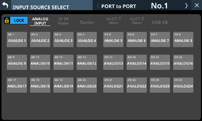
Input sources that are not assigned will appear blank (![]() ).
).
On this screen, view and set routings from input module standpoints, considering “what ports are assigned to the input modules”.
.jpg)
INPUT SOURCE Routing Screen
.jpg)
INSERT SEND Routing Screen
.jpg)
INSERT RETURN Routing Screen
.jpg)
DIRECT OUT Routing Screen
Routing subject switching buttons
These tab buttons select types of routing subjects for the input modules.
This can also be scrolled by tapping the ![]() and
and ![]() buttons or turning LCD knob 1.
buttons or turning LCD knob 1.
![]() /
/ ![]() buttons
buttons
Tap these buttons to select whether to show settings for INPUT A or INPUT B. (Default: ![]() )
)
Input Source display area
These show the input ports that are assigned to the input module from the input sources.
.jpg)
Tap this button to switch to the MODULE (INPUT) Screen for that module. (See “MODULE (INPUT) Screen”.)
Tap this button to switch to the INPUT SOURCE SELECT Screen for the corresponding module. (See “INPUT SOURCE SELECT screen”.)
Input module display
This shows the names of the input modules subject to routing.
The first line shows the MODULE SUB LABEL.
The second line shows the MODULE MAIN LABEL.
The numbers on the right show the number of output ports assigned to that item.
Tap an input module in this area to scroll the Insert Send Routing Setting area () or Direct Out Routing Setting area () to a position that shows a port assigned to that input module.
Output port group page switches
These show output port group page names.
Tap a page name button to switch to the page with the corresponding output port group. The name of the selected page will be highlighted.
This can also be scrolled by tapping the ![]() and
and ![]() buttons or turning LCD knob 8.
buttons or turning LCD knob 8.
Insert Send Routing Setting area
Show and set routings from the insert sends of input modules to output ports here.
Insert send routings can be changed by tapping the intersections of input modules and output ports.
An ![]() icon will appear at the intersection of the input module and output port. The
icon will appear at the intersection of the input module and output port. The ![]() icons can also be tapped to disconnect insert send routings.
icons can also be tapped to disconnect insert send routings.
Insert return display area
These show the input ports that are assigned to the insert returns of input modules.
.jpg)
Tap one of these buttons to switch to the MODULE (OVERVIEW) Screen for that module. (See “CH 1–40 MODULE (OVERVIEW) Screens”.)
Tap this button to switch to the INSERT RETURN PORT SELECT Screen for the corresponding module. (See “INSERT RETURN PORT SELECT screen”.)
DIRECT OUT Routing Setting area
Show and set routings from the direct outs of input modules to output ports here.
Direct out routings can be changed by tapping the intersections of input modules and output ports.
An ![]() icon will appear at the intersection of the input module and output port. The
icon will appear at the intersection of the input module and output port. The ![]() icons can also be tapped to disconnect direct routing routings.
icons can also be tapped to disconnect direct routing routings.
On this screen, view and set routings from output module standpoints, considering “what ports are assigned to the output modules”.
.jpg)
OUTPUT PORT Routing Screen
.jpg)
INSERT SEND Routing Screen
.jpg)
INSERT RETURN Routing Screen
Routing subject switching buttons
These tab buttons select types of routing subjects for the output modules.
This can also be scrolled by tapping the ![]() and
and ![]() buttons or turning LCD knob 1.
buttons or turning LCD knob 1.
Output module display
This shows the names of the output modules subject to routing.
The first line shows the MODULE SUB LABEL.
The second line shows the MODULE MAIN LABEL.
The numbers on the right show the number of output ports assigned to that module.
Tap an OUTPUT MODULE in this area to scroll the Output Port or Insert Send Routing Setting area () to a position that shows an output port with that output module assigned.
Output port group page switches
These show output port group page names.
Tap a page name button to switch to the page with the corresponding output port group.
This can also be scrolled by tapping the ![]() and
and ![]() buttons or turning LCD knob 8.
buttons or turning LCD knob 8.
OUTPUT PORT Routing Setting area
Set routings from output modules to output ports here.
Input routings can be changed by tapping the intersections of output modules and output ports.
An ![]() icon will appear at the intersection of the output module and output port. The
icon will appear at the intersection of the output module and output port. The ![]() icons can also be tapped to disconnect input routings.
icons can also be tapped to disconnect input routings.
Insert Send Routing Setting area
Show and set routings from the insert sends of output modules to output ports here.
Insert send routings can be changed by tapping the intersections of output modules and output ports.
An ![]() icon will appear at the intersection of the output module and output port. The
icon will appear at the intersection of the output module and output port. The ![]() icons can also be tapped to disconnect insert send routings.
icons can also be tapped to disconnect insert send routings.
Insert return display area
These show the input ports that are assigned to the insert returns of output modules.
.jpg)
Tap one of these buttons to switch to the MODULE (OVERVIEW) Screen for that module. (See “MIX 1–22 and MAIN L/R Master MODULE (OVERVIEW) Screens”.)
Tap this button to switch to the INSERT RETURN PORT SELECT Screen for the corresponding module. (See “INSERT RETURN PORT SELECT screen”.)
On this screen, view and set routings from output port standpoints, considering “to where the output ports are assigned”.
.jpg)
ANALOG OUTPUT Port Routing Screen
.jpg)
Dante Port Routing Screen
.jpg)
SLOT 1 Port Routing Screen
.jpg)
SLOT 2 Port Routing Screen
.jpg)
USB OUT Port Routing Screen
Output port group page switches
These show output port group page names.
Tap a page name button to switch to the page with the corresponding output port group.
This can also be scrolled by tapping the ![]() and
and ![]() buttons or turning LCD knob 1.
buttons or turning LCD knob 1.
Output port display area
These show the output sources that are assigned to the output ports.
.jpg)
Tap this button to switch to the OUTPUT PORT SELECT Screen for the corresponding module. (See “OUTPUT PORT SELECT screen”.)
Tap this button to switch to the MODULE (OUTPUT) Screen for that module. (See “MODULE (OUTPUT) Screen”.)
PORT to PORT A.GAIN (INPUT) page
On this screen, show and set analog gain for the following input ports assigned to the PORT to PORT function, which has 24 channels. (The PORT to PORT function takes audio signals that were input through input ports and outputs them from output ports without passing through modules, for example.)
Built-in analog input ports
Analog input connectors of an SB-16D connected through built-in Dante
.jpg)
Input settings display area
Work with input port names, analog GAIN knobs, PAD buttons and 48V buttons in this area.
Analog GAIN levels selected by the frame can be adjusted using the 1–8 LCD knobs that are lit red.
Tap a PAD button to turn the −20 dB pad on/off. When this button is on, it will appear highlighted.
Press and hold the 48V button to turn phantom power (+48V) on/off. When phantom power is on, the button will be highlighted.
Analog GAIN knobs, PAD buttons and 48V buttons can also be used for the input ports of a virtually-mounted SB-16D.
Knobs and buttons will be shown in black and cannot be operated if the input source is an SB-16D for which control privileges are not held.
See “ PAD button” and “ Analog GAIN knob” for details about Analog GAIN and PAD functions.
Use this screen to make settings for the selected module.
Tap areas on the Home Screen or press the SEL key on the top panel to open a MODULE Screen.
Selection buttons for each page are shown at the top of the MODULE Screen.
_No(2025).jpg)
MODULE (INPUT) Screen for CH 1–40 modules
_No(2020).jpg)
MODULE (EQ) Screen for MIX 1–22 modules
NOTE
If the selected module is stereo, a stereo level meter will be shown.
Each level meter has an overload indicator at its top. They will appear to light red when the signal level reaches or exceeds −0.00026 dBFS (16-bit full-scale value).
When a level overload occurs, the entire bar meter will light red.
The area below −60 dBFS at the bottom of the level meters will light when above −70 dBFS.
![]() button
button
Tap this button to return to the Home Screen.
![]() button
button
Tap this button to switch between showing the selected module normally or in full-screen mode, which expands the MODULE Screen to fill the entire touchscreen. When this is on, the button will appear highlighted.
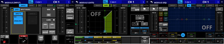
In full-screen mode, it is easy to use all the touchscreens at the same time to adjust, for example, EQ and COMP, or GATE, EQ and COMP.
Turning this button off on one screen will reopen the Home Screen on the other touchscreens.
NOTE
When the GEQ FADER Ctrl function is on, full-screen mode is kept on and cannot be turned off.
![]() /
/![]() buttons
buttons
Tap these buttons to move left and right in order on the layer between modules to show and activate different ones for operation.
When the FULL SCREEN button is off, this will move only between the modules on the current page. For example, moving left and right on the COMP page will move only between the CH 1–40, MIX 1–22 and MAIN L/R Master modules on it.
When the FULL SCREEN button is on, pages become as follows after movement.
If the module after movement is in the same category, the selected page will not change.
If the module after movement is in a different category, it will be shown with the page shown previously in that category.
FIXED MODULE LABEL
This shows the FIXED MODULE LABEL.
USER MODULE LABEL
This shows the MODULE LABEL set as the Main MODULE LABEL. (See “DISPLAY MODE page”.)
If the Main MODULE LABEL display mode is set to “PORT LABEL”, FX RTN 1-4 modules that are not assigned to input and output ports will be shown with the module labels used when the Main MODULE LABEL display mode is set to “USER”.
Tap this area when the Main MODULE LABEL display mode is set to “USER” to open the MODULE LABEL Screen where the user module label and set module color can be changed. (See “DISPLAY MODE page”.) (See “MODULE LABEL page”.)
If the Main MODULE LABEL display mode is set to “PORT LABEL” and the PORT LABEL display mode is set to “USER” (See “DISPLAY MODE page”.), tapping this area will open the USER LABEL (INPUT PORT) or USER LABEL (OUTPUT PORT) Screen where the user port label can be edited for the input/output port assigned to this module. (See “USER LABEL (INPUT PORT / OUTPUT PORT) Screen”.)
No screen will open, however, if no input/output port has been assigned to the module.
![]() button
button
Tap this button to open the MODULE menu for the selected module.
_CH1_pop_Menu.jpg)
Tap menu items to, for example, change parameter settings for the selected module. (See “MODULE menu”.)
Page selection buttons
Tap a page selection button to open that page.
The selected button will be highlighted.
|
Button |
Use |
|
OVERVIEW |
Make overall settings for the selected module. |
|
FX SEND MUTE |
Mute inputs to FX 1–4. |
|
INPUT |
Make input settings for the selected module. |
|
FX |
Make internal effect settings for the selected module. |
|
GATE/EXPANDER/DE-ESSER |
Make dynamics effect settings for the selected module. |
|
EQ |
Make EQ settings for the selected module. |
|
GEQ |
Make GEQ settings for the selected module. |
|
COMP/DUCKER |
Make dynamics effect settings for the selected module. |
|
SEND |
Make bus send settings for the selected module. |
|
PAN |
Make pan settings for the selected module. |
|
OUTPUT |
Make output settings for the selected module. |
NOTE
The INPUT button is only shown for CH 1–40 and ST IN 1–2 modules.
The FX SEND MUTE button is only shown for FX RTN 1–4 modules.
The FX button is only shown for FX RTN 1–4 modules.
The GATE, EXPANDER and DE-ESSER buttons are only shown for CH 1–40 modules.
The GEQ button is only shown for MIX 1–22 and MAIN L/R Master modules.
The COMP and DUCKER buttons are only shown for CH 1–40, MIX 1–22 and MAIN L/R master modules.
The OUTPUT button is only shown for MIX 1–22 and MAIN L/R master modules.
Make overall modules settings on the MODULE (OVERVIEW) Screen, which every module has.
On this screen, signal processing flows from left to right, and the settings for the functions of the modules are shown.
Tap the MODULE LABEL area on the Home Screen to open this screen.
CH 1–40 MODULE (OVERVIEW) Screens
_CH1_No(2024).jpg)
CH 1–40 modules when the stereo link setting is off
_CH1-2_No(2024).jpg)
CH 1–40 modules when the stereo link setting is on
Metering Point button
This shows the name of the set metering point.
Tap this button to open a window for setting metering points for CH 1–40 modules.
_MeteringPoint_SelectPop.jpg)
Options: INPUT, PRE HPF (default), PRE EQ, POST EQ, PRE FADER, POST FADER
Tap an option to switch the metering point for the level meter.
NOTE
Metering points can also be changed on the METERING POINT page of the METER SETUP Screen. (See “METERING POINT page”.)
Level meters
This shows the level of the signal at the set metering point.
MUTE GROUP button
Tap this button to open the DCA/Mute Group SETUP Screen Mute Group Assign page. (See “Mute Group Assign page”.)
DCA button
Tap this button to open the DCA/Mute Group SETUP Screen DCA Assign page. (See “DCA Assign page”.)
MUTE GROUP 1–8 buttons
Tap these buttons to change Mute Group assignment states. (Default: off)
Assigned buttons will be highlighted.
DCA 1–8 buttons
Tap these buttons to change DCA assignment states. (Default: off)
Assigned buttons will be highlighted.
Metering Point position indicator
The highlighted indicator shows the position of the set metering point.
Snapshot Recall Safe button
Tap this button to enable the Snapshot Recall Safe function for the selected module. (Default: off)
When this is on, the button will appear highlighted.
NOTE
This can also be set on the MODULE SAFE page of the SNAPSHOT RECALL SAFE Screen. (See “MODULE SAFE page”.)
Insert Point
This shows the name of the set insert point.
Tap this button to open a window for setting the insert point for the selected module.
_InsertPoint_SelectPop.jpg)
Options: PRE EQ (default), PRE FADER
NOTE
Settings can be made for all CH 1–40 insert points at once using INSERT POINT BATCH SETUP on the CH 1–40 CONFIG page of the MIXER CONFIG Screen. (See “CH 1–40 CONFIG page”.)
INPUT button
This shows the input source name.
The second line shows an abbreviation of the FIXED PORT LABEL.
The third line shows the USER PORT LABEL.
If the USER PORT LABEL is undefined, the FIXED PORT LABEL will be shown.
If the module is stereo, the FIXED PORT LABEL for the input sources will appear split left and right and abbreviated as follows.
|
Module name shown |
Stereo module name shown |
|
ANALOG |
AN |
|
Dante |
DA |
|
SLOT 1 |
S1 |
|
SLOT 2 |
S2 |
|
USB IN |
USB |
|
ST IN 1 |
ST1 |
|
ST IN 2 |
ST2 |
|
PLAYER |
PL |
![]()
If Dante ports that have mounted SB-16Ds assigned are selected, they will be shown as follows.
2nd line: DA port number
3rd line: #[ID] port number
4th line: USER PORT LABEL or SB #[ID] port number (if the USER PORT LABEL is undefined)
![]()
If it is a virtually-mounted SB-16D, ![]() will appear.
will appear.
![]()
Tap this button to open the INPUT SOURCE SELECT Screen. (See “INPUT SOURCE SELECT screen”.)
+48V button
This shows the +48V button when the input source of the selected module is “ANALOG” or “SB-16D connected by built-in Dante”.
Press and hold the +48V button to turn phantom power (+48V) on/off. (This is off by default.)
When phantom power is on, the button will be highlighted.
A black button that cannot be operated will be shown if the input source is an SB-16D for which control privileges are not held.
This shows the PAD button when the input source of the selected module is “ANALOG” or “SB-16D connected by built-in Dante”.
Tap this button to turn the −20 dB pad on/off. (Default: off)
When this button is on, it will appear highlighted.
A black button that cannot be operated will be shown if the input source is an SB-16D for which control privileges are not held.
NOTE
When the pad is switched on/off, the Analog GAIN value will be controlled as shown below so that it changes as little as possible.
When Analog Reference Level is +6 dBu and Digital Reference Level is −9 dBFS
|
Status before switching pad setting |
Analog GAIN after switching pad setting |
|
Analog GAIN: +3 – +37 |
Same value |
|
PAD ON/Analog GAIN: −17 – +2 |
+3 |
|
PAD OFF/Analog GAIN: +38 – +57 |
+37 |
When Analog Reference Level is +4 dBu and Digital Reference Level is −20 dBFS
|
Status before switching pad setting |
Analog GAIN after switching pad setting |
|
Analog GAIN: +12 – +46 |
Same value |
|
PAD ON/Analog GAIN: −8 – +11 |
+12 |
|
PAD OFF/Analog GAIN: +47 – +66 |
+46 |
When Analog Reference Level is +4 dBu and Digital Reference Level is −18 dBFS
|
Status before switching pad setting |
Analog GAIN after switching pad setting |
|
Analog GAIN: +10 – +44 |
Same value |
|
PAD ON/Analog GAIN: −10 – +9 |
+10 |
|
PAD OFF/Analog GAIN: +45 – +64 |
+44 |
When Analog Reference Level is +4 dBu and Digital Reference Level is −16 dBFS
|
Status before switching pad setting |
Analog GAIN after switching pad setting |
|
Analog GAIN: +8 – +42 |
Same value |
|
PAD ON/Analog GAIN: −12 – +7 |
+8 |
|
PAD OFF/Analog GAIN: +43 – +62 |
+42 |
When Analog Reference Level is +4 dBu and Digital Reference Level is −14 dBFS
|
Status before switching pad setting |
Analog GAIN after switching pad setting |
|
Analog GAIN: +6 – +40 |
Same value |
|
PAD ON/Analog GAIN: −14 – +5 |
+6 |
|
PAD OFF/Analog GAIN: +41 – +60 |
+40 |
When Analog Reference Level is 0 dBu and Digital Reference Level is −20 dBFS
|
Status before switching pad setting |
Analog GAIN after switching pad setting |
|
Analog GAIN: +8 – +42 |
Same value |
|
PAD ON/Analog GAIN: −12 – +7 |
+8 |
|
PAD OFF/Analog GAIN: +43 – +62 |
+42 |
When Analog Reference Level is 0 dBu and Digital Reference Level is −18 dBFS
|
Status before switching pad setting |
Analog GAIN after switching pad setting |
|
Analog GAIN: +6 – +40 |
Same value |
|
PAD ON/Analog GAIN: −14 – +5 |
+6 |
|
PAD OFF/Analog GAIN: +41 – +60 |
+40 |
When the input source of the selected module is “ANALOG” or “SB-16D connected by built-in Dante”, an analog gain knob will be shown for this unit or the SB-16D that can be used to adjust the input level of the MIC/LINE input jack.
Turn LCD knob 1 (lit red) to adjust it.
When Analog Reference Level is +6 dBu and Digital Reference Level is −9 dBFS
|
PAD button setting |
Range |
|
OFF |
+3 (default) – +57 |
|
ON |
−17 – +37 |
When Analog Reference Level is +4 dBu and Digital Reference Level is −20 dBFS
|
PAD button setting |
Range |
|
OFF |
+12 (default) – +66 |
|
ON |
−8 – +46 |
When Analog Reference Level is +4 dBu and Digital Reference Level is −18 dBFS
|
PAD button setting |
Range |
|
OFF |
+10 (default) – +64 |
|
ON |
−10 – +44 |
When Analog Reference Level is +4 dBu and Digital Reference Level is −16 dBFS
|
PAD button setting |
Range |
|
OFF |
+8 (default) – +62 |
|
ON |
−12 – +42 |
When Analog Reference Level is +4 dBu and Digital Reference Level is −14 dBFS
|
PAD button setting |
Range |
|
OFF |
+6 (default) – +60 |
|
ON |
−14 – +40 |
When Analog Reference Level is 0 dBu and Digital Reference Level is −20 dBFS
|
PAD button setting |
Range |
|
OFF |
+8 (default) – +62 |
|
ON |
−12 – +42 |
When Analog Reference Level is 0 dBu and Digital Reference Level is −18 dBFS
|
PAD button setting |
Range |
|
OFF |
+6 (default) – +60 |
|
ON |
−14 – +40 |
The indicators to the left of the Analog GAIN knobs appear to light as shown below depending on the input level.
Red: −3 dBFS, Green: −40 dBFS
When the input source of the selected module is “ANALOG” or “SB-16D connected by built-in Dante” and the Stereo Link setting is on, 2 Analog GAIN knobs will be shown for the linked channels.
Turn LCD knob 1 (lit red) to adjust both together.
To operate them separately, do so on the MODULE (INPUT) screen after turning the GANG function OFF on that screen.
A black knob that cannot be operated will be shown if the input source is an SB-16D for which control privileges are not held.
NOTE
Explanation of Analog GAIN values
When signals at the Analog Reference Level (+6 dBu, +4 dBu, 0 dBu) are input, the Analog GAIN value that becomes the Digital Reference Level (−9 dBFS, −14 dBFS, −16 dBFS, −18 dBFS, −20 dBFS) at the digital stage is shown as “0”.
DIRECT OUT button
Tap this button to turn DIRECT OUT on/off. (Default: ON)
When ON, the signal will be output directly from this point, and this button and the DIRECT OUT TRIM knob will be highlighted.
NOTE
The DIRECT OUT POINT for CH 1–40 modules can also be changed as explained in “CH 1–40 CONFIG page”.
DIRECT OUT TRIM knob
Use this to adjust the DIRECT OUT output signal level.
Range: −20 dB – +20 dB (default: 0 dB)
Turn LCD knob 2/4/5/7 (lit blue) to adjust it.
NOTE
The knob used for this operation depends on DIRECT OUT POINT and DELAY POINT settings (“CH 1–40 CONFIG page”).
OUTPUT button
This shows the name of the output port that the DIRECT OUT signal is assigned to.
The second line shows an abbreviation of the FIXED PORT LABEL.
The third line shows the USER PORT LABEL.
If the USER PORT LABEL is undefined, the FIXED PORT LABEL will be shown.
If it has been assigned to multiple output ports, “…” will appear to the bottom right of the button.
If the module is stereo, the FIXED PORT LABEL for the output ports will appear split left and right and abbreviated as follows.
|
Module name shown |
Stereo module name shown |
|
ANALOG |
AN |
|
Dante |
DA |
|
SLOT 1 |
S1 |
|
SLOT 2 |
S2 |
|
USB OUT |
USB |
![]()
If Dante ports that have mounted SB-16Ds assigned are selected, they will be shown as follows.
2nd line: DA port number
3rd line: #[ID] port number
4th line: USER PORT LABEL or SB #[ID] port number (if the USER PORT LABEL is undefined)
![]()
If it is a virtually-mounted SB-16D, ![]() will appear.
will appear.
![]()
Tap this button to open the DIRECT OUT SELECT Screen. (See “DIRECT OUT PORT SELECT screen”.)
Phase buttons
Use these to change the phases of the signals for the selected module.
Tap these buttons to reverse the phases of the selected module signals.
Phase button display when the Stereo Link setting is off for the selected module
|
|
Normal |
|
|
Reversed |
Phase button display when the selected module is stereo
|
|
Normal |
|
|
Reversed |
D.TRIM knob
Use this to adjust the digital trim value.
Range: −50.0 dB – +20.0 dB (default: 0.0 dB)
Turn LCD knob 2/3/4 (lit red) to adjust it.
When the Stereo Link setting for the selected module is on, 2 D.TRIM knobs will be shown together for the linked channels.
Turn LCD knobs 2/3/4 (lit red) to adjust both together.
To operate them separately, do so on the MODULE (INPUT) screen after turning the GANG function OFF on that screen.
NOTE
The knob used for this operation depends on DIRECT OUT POINT and DELAY POINT settings (“CH 1–40 CONFIG page”).
HPF button
Tap this button to turn the HPF on/off. (Default: OFF)
When this is ON, the button will appear highlighted.
HPF frequency
This adjusts the cutoff frequency of the HPF.
Range: 20 Hz – 1.0 kHz (default: 79 Hz)
Turn LCD knob 3/4/5 (lit blue) to adjust it.
When this is on, it will appear highlighted.
NOTE
The knob used for this operation depends on DIRECT OUT POINT and DELAY POINT settings (“CH 1–40 CONFIG page”).
SEND button
This shows the name of the output port that the INSERT SEND signal is assigned to.
The second line shows an abbreviation of the FIXED PORT LABEL.
The third line shows the USER PORT LABEL.
If the USER PORT LABEL is undefined, the FIXED PORT LABEL will be shown.
If it has been assigned to multiple output ports, “…” will appear to the bottom right of the button.
If the module is stereo, the FIXED PORT LABEL for the output ports will appear split left and right and abbreviated as follows.
|
Module name shown |
Stereo module name shown |
|
ANALOG |
AN |
|
Dante |
DA |
|
SLOT 1 |
S1 |
|
SLOT 2 |
S2 |
|
USB OUT |
USB |
![]()
If Dante ports that have mounted SB-16Ds assigned are selected, they will be shown as follows.
2nd line: DA port number
3rd line: #[ID] port number
4th line: USER PORT LABEL or SB #[ID] port number (if the USER PORT LABEL is undefined)
![]()
If it is a virtually-mounted SB-16D, ![]() will appear.
will appear.
![]()
Tap this button to open the INSERT SEND PORT SELECT Screen. (See “INSERT SEND PORT SELECT screen”.)
INSERT button
Tap this button to turn the INSERT on/off. (Default: OFF)
When this is on, the button will appear highlighted.
RETURN button
This shows the name of the input port that is assigned for the INSERT RETURN signal.
The second line shows an abbreviation of the FIXED PORT LABEL.
The third line shows the USER PORT LABEL.
If the USER PORT LABEL is undefined, the FIXED PORT LABEL will be shown.
If the module is stereo, the FIXED PORT LABEL for the input ports will appear split left and right and abbreviated as follows.
|
Module name shown |
Stereo module name shown |
|
ANALOG |
AN |
|
Dante |
DA |
|
SLOT 1 |
S1 |
|
SLOT 2 |
S2 |
|
USB IN |
USB |
|
ST IN 1 |
ST1 |
|
ST IN 2 |
ST2 |
|
PLAYER |
PL |
|
SB-16D |
SB |
![]()
If Dante ports that have mounted SB-16Ds assigned are selected, they will be shown as follows.
2nd line: DA port number
3rd line: #[ID] port number
4th line: USER PORT LABEL or SB #[ID] port number (if the USER PORT LABEL is undefined)
![]()
If it is a virtually-mounted SB-16D, ![]() will appear.
will appear.
![]()
Tap this button to open the INSERT RETURN PORT SELECT Screen. (See “INSERT RETURN PORT SELECT screen”.)
When the INSERT RETURN PORT of the selected module is “ANALOG” or “SB-16D connected by built-in Dante”, the Analog GAIN value will be shown to the left of the RETURN button.
_CH1.jpg)
_CH15-16.jpg)
Tapping the Analog GAIN value to the left of the RETURN button will show the Analog GAIN value that corresponds to the INSERT RETURN PORT to the left of the INSERT button. Use the LCD knob (lit red) below the shown Analog GAIN value to adjust the Analog GAIN.
_CH1_InsRtnGain.jpg)
_CH15-16_InsRtnGain.jpg)
Tap the Set to LINE LEVEL button to set the corresponding Pre Amp setting as follows.
PAD: ON
Analog GAIN: 0
Phantom: OFF
DELAY button
Tap this button to turn on/off the DELAY function, which corrects for input signal latency. (Default: OFF)
When this is on, the button will appear highlighted.
DELAY TIME
This adjusts the DELAY TIME.
The highlighted unit will be used for operation, so tap the button for the desired unit.
|
Unit options |
Range (unit) |
|
meter |
0 – 117.3 (meter) |
|
feet |
0 – 384.8 (feet) |
|
msec (default) |
0 – 341.32 (msec) |
Turn LCD knob 2/3/5/6 (lit green) to adjust it.
NOTE
The DELAY POINT for CH 1–40 modules can also be changed as explained in “CH 1–40 CONFIG page”.
The knob used for this operation depends on DIRECT OUT POINT and DELAY POINT settings (“CH 1–40 CONFIG page”).
MUTE button
Tap this button to turn muting on/off for the selected module signal.
When MUTE is on, the button will be highlighted.
NOTE
The MUTE keys on the top of the unit can also be used to set this.
FADER LEVEL
Use this to adjust the FADER level of the selected module signal.
Range: −∞ dB – +10.0 dB (default: −∞ dB)
Turn LCD knob 6/7 (lit blue) to adjust it.
NOTE
The channel faders on top of the unit can also be used for this adjustment.
The knob number used for this operation depends on DIRECT OUT POINT setting (“CH 1–40 CONFIG page”).
Tap the area while pressing the HOME key on the top panel to set the FADER level to 0 dB.
SENDS button
Tap this button to open the MODULE (SEND/PAN) Screen for the selected module. (See “MODULE (SEND/PAN) Screen”.)
ON/OFF button for the Audio Follow Video function
Tap this button to turn on/off the Audio Follow Video function of the selected module. When this is on, the button will appear highlighted.
This shows the name of the AFV TRIGGER SOURCE selected on the AFV TRIGGER SOURCE SELECT Screen
AFV button
Tap this button to open the MODULE (Audio Follow Video) Screen for the selected module. (See “MODULE (Audio Follow Video) Screen”.)
MIX/FX SEND level indicators
This list shows the on/off and PRE/POST states and the send levels to the MIX 1–22 and FX 1–4 buses.
Tap this area to open the MODULE (SEND/PAN) Screen for the selected module with the bus selected for the tapped area.
PAN/BAL
This adjusts the panning/balance of the signals sent to the MAIN L/R bus. Turn LCD knob 8 (lit yellow) to adjust it.
Range: L100 – C – R100 (default: C)
When the ![]() icon is highlighted (
icon is highlighted (![]() ), signals are being sent to the MAIN L/R bus.
), signals are being sent to the MAIN L/R bus.
Tap this area to open the MODULE (SEND/PAN) Screen for the selected module. (See “MODULE (SEND/PAN) Screen”.)
NOTE
Tap this area while pressing the HOME key on the top panel to set panning/balance to center (C).
AUTO MIXER button (CH 1–16 modules only)
This shows the name of the AUTO MIXER group (A/B/C/D) to which the corresponding channel module belongs.
If the selected group is TOP PRIORITY, a “TOP” icon will be shown in the bottom left of the button. When on, the icon will appear highlighted.
This will be dimmed when the AUTO MIXER is off.
Tap this button to open the AUTOMATIC MIXER Screen. (See “AUTO MIXER Function”.)
ST IN 1–2 MODULE (OVERVIEW) Screens
_ST-IN_No(2024).jpg)
ST IN 1–2 module when the input source is ANALOG
Metering Point button
This shows the name of the set metering point.
Tap this button to open a window for setting metering points for ST IN 1–2 modules.
_ST-IN1_MeteringPoint_SelectPop.jpg)
Options: INPUT, PRE EQ (default), PRE FADER, POST FADER
Tap an option to switch the metering point for the level meter.
NOTE
Metering points can also be changed on the METERING POINT page of the METER SETUP Screen. (See “METERING POINT page”.)
Level meters
This shows the level of the signal at the set metering point.
MUTE GROUP button
Tap this button to open the DCA/Mute Group SETUP Screen Mute Group Assign page. (See “Mute Group Assign page”.)
DCA button
Tap this button to open the DCA/Mute Group SETUP Screen DCA Assign page. (See “DCA Assign page”.)
MUTE GROUP 1–8 buttons
Tap these buttons to change Mute Group assignment states. (Default: off)
Assigned buttons will be highlighted.
DCA 1–8 buttons
Tap these buttons to change DCA assignment states. (Default: off)
Assigned buttons will be highlighted.
Snapshot Recall Safe button
Tap this button to enable the Snapshot Recall Safe function for the selected module. (Default: off)
When this is on, the button will appear highlighted.
NOTE
This can also be set on the MODULE SAFE page of the SNAPSHOT RECALL SAFE Screen. (See “MODULE SAFE page”.)
Metering Point position indicator
The highlighted indicator shows the position of the set metering point.
INPUT button
This shows the input source name. In this case, the FIXED PORT LABEL of the input source will appear split left and right and abbreviated as follows.
|
Module name shown |
Stereo module name shown |
|
ANALOG |
AN |
|
Dante |
DA |
|
SLOT 1 |
S1 |
|
SLOT 2 |
S2 |
|
USB IN |
USB |
|
ST IN 1 |
ST1 |
|
ST IN 2 |
ST2 |
|
PLAYER |
PL |
![]()
If Dante ports that have mounted SB-16Ds assigned are selected, they will be shown as follows.
2nd line: DA port number
3rd line: SB #[ID] port number
4th line: USER PORT LABEL or SB #[ID] port number (if the USER PORT LABEL is undefined)
![]()
If it is a virtually-mounted SB-16D, ![]() will appear.
will appear.
![]()
Tap this button to open the INPUT SOURCE SELECT Screen. (See “INPUT SOURCE SELECT screen”.)
+48V button
This shows the +48V button when the input source of the selected module is “ANALOG” or “SB-16D connected by built-in Dante”.
Press and hold the +48V button to turn phantom power (+48V) on/off. (This is off by default.)
When phantom power is on, the button will be highlighted.
A black button that cannot be operated will be shown if the input source is an SB-16D for which control privileges are not held.
PAD button
This shows the PAD button when the input source of the selected module is “ANALOG” or “SB-16D connected by built-in Dante”.
Tap this button to turn the −20 dB pad on/off. (Default: off)
When this button is on, it will appear highlighted.
A black button that cannot be operated will be shown if the input source is an SB-16D for which control privileges are not held.
NOTE
When the pad is switched on/off, the Analog GAIN value will be controlled as shown below so that it changes as little as possible.
When Analog Reference Level is +6 dBu and Digital Reference Level is −9 dBFS
|
Status before switching pad setting |
Analog GAIN after switching pad setting |
|
Analog GAIN: +3 – +37 |
Same value |
|
PAD ON/Analog GAIN: −17 – +2 |
+3 |
|
PAD OFF/Analog GAIN: +38 – +57 |
+37 |
When Analog Reference Level is +4 dBu and Digital Reference Level is −20 dBFS
|
Status before switching pad setting |
Analog GAIN after switching pad setting |
|
Analog GAIN: +12 – +46 |
Same value |
|
PAD ON/Analog GAIN: −8 – +11 |
+12 |
|
PAD OFF/Analog GAIN: +47 – +66 |
+46 |
When Analog Reference Level is +4 dBu and Digital Reference Level is −18 dBFS
|
Status before switching pad setting |
Analog GAIN after switching pad setting |
|
Analog GAIN: +10 – +44 |
Same value |
|
PAD ON/Analog GAIN: −10 – +9 |
+10 |
|
PAD OFF/Analog GAIN: +45 – +64 |
+44 |
When Analog Reference Level is +4 dBu and Digital Reference Level is −16 dBFS
|
Status before switching pad setting |
Analog GAIN after switching pad setting |
|
Analog GAIN: +8 – +42 |
Same value |
|
PAD ON/Analog GAIN: −12 – +7 |
+8 |
|
PAD OFF/Analog GAIN: +43 – +62 |
+42 |
When Analog Reference Level is +4 dBu and Digital Reference Level is −14 dBFS
|
Status before switching pad setting |
Analog GAIN after switching pad setting |
|
Analog GAIN: +6 – +40 |
Same value |
|
PAD ON/Analog GAIN: −14 – +5 |
+6 |
|
PAD OFF/Analog GAIN: +41 – +60 |
+40 |
When Analog Reference Level is 0 dBu and Digital Reference Level is −20 dBFS
|
Status before switching pad setting |
Analog GAIN after switching pad setting |
|
Analog GAIN: +8 – +42 |
Same value |
|
PAD ON/Analog GAIN: −12 – +7 |
+8 |
|
PAD OFF/Analog GAIN: +43 – +62 |
+42 |
When Analog Reference Level is 0 dBu and Digital Reference Level is −18 dBFS
|
Status before switching pad setting |
Analog GAIN after switching pad setting |
|
Analog GAIN: +6 – +40 |
Same value |
|
PAD ON/Analog GAIN: −14 – +5 |
+6 |
|
PAD OFF/Analog GAIN: +41 – +60 |
+40 |
Analog GAIN knobs
When the input source of the selected module is “ANALOG” or “SB-16D connected by built-in Dante”, this will show analog gain knobs for each channel of this unit or the SB-16D. These can be used to adjust input levels of MIC/LINE input jacks.
Turn LCD knob 1 (lit red) to adjust it.
When Analog Reference Level is +6 dBu and Digital Reference Level is −9 dBFS
|
PAD button setting |
Range |
|
OFF |
+3 (default) – +57 |
|
ON |
−17 – +37 |
When Analog Reference Level is +4 dBu and Digital Reference Level is −20 dBFS
|
PAD button setting |
Range |
|
OFF |
+12 (default) – +66 |
|
ON |
−8 – +46 |
When Analog Reference Level is +4 dBu and Digital Reference Level is −18 dBFS
|
PAD button setting |
Range |
|
OFF |
+10 (default) – +64 |
|
ON |
−10 – +44 |
When Analog Reference Level is +4 dBu and Digital Reference Level is −16 dBFS
|
PAD button setting |
Range |
|
OFF |
+8 (default) – +62 |
|
ON |
−12 – +42 |
When Analog Reference Level is +4 dBu and Digital Reference Level is −14 dBFS
|
PAD button setting |
Range |
|
OFF |
+6 (default) – +60 |
|
ON |
−14 – +40 |
When Analog Reference Level is 0 dBu and Digital Reference Level is −20 dBFS
|
PAD button setting |
Range |
|
OFF |
+8 (default) – +62 |
|
ON |
−12 – +42 |
When Analog Reference Level is 0 dBu and Digital Reference Level is −18 dBFS
|
PAD button setting |
Range |
|
OFF |
+6 (default) – +60 |
|
ON |
−14 – +40 |
The indicators to the left of the Analog GAIN knobs appear to light as shown below depending on the input level.
Red: −3 dBFS, Green: −40 dBFS
When the input source of the selected module is “ANALOG” or “SB-16D connected by built-in Dante”, 2 Analog GAIN knobs will be shown together.
Turn LCD knob 1 (lit red) to adjust both together.
To operate them separately, do so on the MODULE (INPUT) screen after turning the GANG function OFF on that screen.
A black knob that cannot be operated will be shown if the input source is an SB-16D for which control privileges are not held.
NOTE
Explanation of Analog GAIN values
When signals at the Analog Reference Level (+6 dBu, +4 dBu, 0 dBu) are input, the Analog GAIN value that becomes the Digital Reference Level (−9 dBFS, −14 dBFS, −16 dBFS, −18 dBFS, −20 dBFS) at the digital stage is shown as “0”.
Phase buttons
Use these to change the phases of the signals for the selected module.
Tap these buttons to reverse the phases of the selected module signals.
|
|
Normal |
|
|
Reversed |
D.TRIM knob
Use this to adjust the digital trim value.
Range: −50.0 dB – +20.0 dB (default: 0.0 dB)
Turn LCD knob 3 (lit red) to adjust it.
Two D.TRIM knobs will be shown together for the L and R channels.
Turn LCD knob 3 (lit red) to adjust both together.
To operate them separately, do so on the MODULE (INPUT) screen after turning the GANG function OFF on that screen.
MUTE button
Tap this button to turn muting on/off for the selected module signal.
When MUTE is on, the button will be highlighted.
NOTE
The MUTE keys on the top of the unit can also be used to set this.
FADER LEVEL
Use this to adjust the FADER level of the selected module signal.
Range: −∞ dB – +10.0 dB (default: −∞ dB)
Turn LCD knob 7 (lit blue) to adjust it.
NOTE
The channel faders on top of the unit can also be used for this adjustment.
Tap the area while pressing the HOME key on the top panel to set the FADER level to 0 dB.
SENDS button
Tap this button to open the MODULE (SEND/PAN) Screen for the selected module. (See “MODULE (SEND/PAN) Screen”.)
ON/OFF button for the Audio Follow Video function
Tap this button to turn on/off the Audio Follow Video function of the selected module. When this is on, the button will appear highlighted.
This shows the name of the AFV TRIGGER SOURCE selected on the AFV TRIGGER SOURCE SELECT Screen.
AFV button
Tap this button to open the MODULE (Audio Follow Video) Screen for the selected module. (See “MODULE (Audio Follow Video) Screen”.)
MIX/FX SEND level indicators
This list shows the on/off and PRE/POST states and the send levels to the MIX 1–22 and FX 1–4 buses.
Tap this area to open the MODULE (SEND/PAN) Screen for the selected module with the bus selected for the tapped area.
BAL
This adjusts the balance of the signals sent to the MAIN L/R bus. Turn LCD knob 8 (lit yellow) to adjust it.
Range: L100 – C – R100 (default: C)
When the ![]() icon is highlighted (
icon is highlighted (![]() ), signals are being sent to the MAIN L/R bus.
), signals are being sent to the MAIN L/R bus.
Tap this area to open the MODULE (SEND/PAN) Screen for the selected module. (See “MODULE (SEND/PAN) Screen”.)
NOTE
Tap this area while pressing the HOME key on the top panel to set the balance to center (C).
FX RTN 1–4 MODULE (OVERVIEW) Screens
_FX-RTN1_No(2025).jpg)
Metering Point button
This shows the name of the set metering point.
Tap this button to open a window for setting metering points for FX RTN 1–4 modules.
_FX-RTN1_MeteringPoint_SelectPop.jpg)
Options: FX INPUT, FX OUTPUT (default), PRE FADER, POST FADER
Tap an option to switch the metering point for the level meter.
NOTE
Metering points can also be changed on the METERING POINT page of the METER SETUP Screen. (See “METERING POINT page”.)
Level meters
This shows the level of the signal at the set metering point.
MUTE GROUP button
Tap this button to open the DCA/Mute Group SETUP Screen Mute Group Assign page. (See “Mute Group Assign page”.)
DCA button
Tap this button to open the DCA/Mute Group SETUP Screen DCA Assign page. (See “DCA Assign page”.)
SEND OVERVIEW button
Tap this button to open the SEND OVERVIEW Screen for the selected FX RTN module. (See “FX 1–4 bus SEND OVERVIEW Screen”.)
MUTE GROUP 1–8 buttons
Tap these buttons to change Mute Group assignment states. (Default: off)
Assigned buttons will be highlighted.
DCA 1–8 buttons
Tap these buttons to change DCA assignment states. (Default: off)
Assigned buttons will be highlighted.
Snapshot Recall Safe button
Tap this button to enable the Snapshot Recall Safe function for the selected module. (Default: off)
When this is on, the button will appear highlighted.
NOTE
This can also be set on the MODULE SAFE page of the SNAPSHOT RECALL SAFE Screen. (See “MODULE SAFE page”.)
Metering Point position indicator
The highlighted indicator shows the position of the set metering point.
FX Processing button
Tap this button to open the MODULE (FX) Screen. (See “MODULE (FX) Screen”.)
MUTE button
Tap this button to turn muting on/off for the selected module signal.
When MUTE is on, the button will be highlighted.
NOTE
The MUTE keys on the top of the unit can also be used to set this.
FADER LEVEL
Use this to adjust the FADER level of the selected module signal.
Range: −∞ dB – +10.0 dB (default: 0.0 dB)
Turn LCD knob 7 (lit blue) to adjust it.
NOTE
The channel faders on top of the unit can also be used for this adjustment.
Tap the area while pressing the HOME key on the top panel to set the FADER level to 0 dB.
SENDS button
Tap this button to open the MODULE (SEND/PAN) Screen for the selected module. (See “MODULE (SEND/PAN) Screen”.)
ON/OFF button for the Audio Follow Video function
Tap this button to turn on/off the Audio Follow Video function of the selected module. When this is on, the button will appear highlighted.
This shows the name of the AFV TRIGGER SOURCE selected on the AFV TRIGGER SOURCE SELECT Screen.
AFV button
Tap this button to open the MODULE (Audio Follow Video) Screen for the selected module. (See “MODULE (Audio Follow Video) Screen”.)
MIX/FX SEND level indicators
This list shows the on/off and PRE/POST states and the send levels to the MIX 1–22 and FX 1–4 buses.
Tap this area to open the MODULE (SEND/PAN) Screen for the selected module with the bus selected for the tapped area.
BAL
This adjusts the balance of the signals sent to the MAIN L/R bus. Turn LCD knob 8 (lit yellow) to adjust it.
Range: L100 – C – R100 (default: C)
When the ![]() icon is highlighted (
icon is highlighted (![]() ), signals are being sent to the MAIN L/R bus.
), signals are being sent to the MAIN L/R bus.
Tap this area to open the MODULE (SEND/PAN) Screen for the selected module. (See “MODULE (SEND/PAN) Screen”.)
NOTE
Tap this area while pressing the HOME key on the top panel to set the balance to center (C).
FX SEND MUTE button
Tap this button to turn FX SEND MUTE on/off. (Default: off)
_FX-RTN1_FxSendMute_On.jpg)
When this is on, the button will appear highlighted. In addition, when it is on, the FX RTN 1-4 modules on the Home Screen will also be highlighted red.
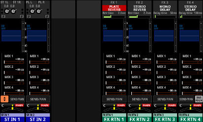
MIX 1–22 and MAIN L/R Master MODULE (OVERVIEW) Screens
_MIX1_No(2024).jpg)
MIX 1–22 modules
_MIX1-2_No(2024).jpg)
MIX 1–22 modules with Stereo Link on
_MAIN-LR_No(2024).jpg)
MAIN L/R Master module
Metering Point button
This shows the name of the set metering point.
Tap this button to open a window for setting the metering point.
Metering point settings for the MIX 1–22 modules and the MAIN L/R Master module are set separately for the AUX mode bus MAIN L/R module and the GROUP mode bus.
_MIX1_MeteringPoint_SelectPop.jpg)
Options: INPUT, POST EQ, POST GEQ, PRE FADER, POST FADER, OUTPUT
|
Aux mode bus and MAIN L/R module defaults |
OUTPUT |
|
GROUP mode bus default |
POST FADER |
Tap an option to switch the metering point for the level meter.
NOTE
Metering points can also be changed on the METERING POINT page of the METER SETUP Screen. (See “METERING POINT page”.)
When the Metering Point is OUTPUT, and the corresponding bus has not been assigned to an output port (not being output from the unit), meters will not be shown.
Level meters
This shows the level of the signal at the set metering point.
MUTE GROUP button
Tap this button to open the DCA/Mute Group SETUP Screen Mute Group Assign page. (See “Mute Group Assign page”.)
DCA button
Tap this button to open the DCA/Mute Group SETUP Screen DCA Assign page. (See “DCA Assign page”.)
SEND OVERVIEW button
Tap this button to open the SEND OVERVIEW Screen for the selected module. (See “MIX 1–22 bus SEND OVERVIEW Screen” and “MAIN L/R bus SEND OVERVIEW Screen”.)
MUTE GROUP 1–8 buttons
Tap these buttons to change Mute Group assignment states. (Default: off)
Assigned buttons will be highlighted.
DCA 1–8 buttons
Tap these buttons to change DCA assignment states. (Default: off)
Assigned buttons will be highlighted.
Snapshot Recall Safe button
Tap this button to enable the Snapshot Recall Safe function for the selected module. (Default: off)
When this is on, the button will appear highlighted.
NOTE
This can also be set on the MODULE SAFE page of the SNAPSHOT RECALL SAFE Screen. (See “MODULE SAFE page”.)
Metering Point position indicator
This shows the position of the set metering point.
SEND button
This shows the name of the output port that the INSERT SEND signal is assigned to.
The second line shows an abbreviation of the FIXED PORT LABEL.
The third line shows the USER PORT LABEL.
If the USER PORT LABEL is undefined, the FIXED PORT LABEL will be shown.
If it has been assigned to multiple output ports, “…” will appear to the bottom right of the button.
If the module is stereo, the FIXED PORT LABEL for the output ports will appear split left and right and abbreviated as follows.
|
Module name shown |
Stereo module name shown |
|
ANALOG |
AN |
|
Dante |
DA |
|
SLOT 1 |
S1 |
|
SLOT 2 |
S2 |
|
USB OUT |
USB |
![]()
Tap this button to open the INSERT SEND PORT SELECT Screen. (See “INSERT SEND PORT SELECT screen”.)
INSERT button
Tap this button to turn the INSERT on/off. (Default: OFF)
When this is ON, the button will appear highlighted.
RETURN button
This shows the name of the input port that is assigned for the INSERT RETURN signal.
The second line shows an abbreviation of the FIXED PORT LABEL.
The third line shows the USER PORT LABEL.
If the USER PORT LABEL is undefined, the FIXED PORT LABEL will be shown.
If the module is stereo, the FIXED PORT LABEL for the input ports will appear split left and right and abbreviated as follows.
|
Module name shown |
Stereo module name shown |
|
ANALOG |
AN |
|
Dante |
DA |
|
SLOT 1 |
S1 |
|
SLOT 2 |
S2 |
|
USB OUT |
USB |
|
ST IN 1 |
ST1 |
|
ST IN 2 |
ST2 |
|
PLAYER |
PL |
|
SB-16D |
SB |
![]()
Tap this button to open the INSERT RETURN PORT SELECT Screen. (See “INSERT RETURN PORT SELECT screen”.)
When the INSERT RETURN PORT of the selected module is “ANALOG” or “SB-16D connected by built-in Dante”, the Analog GAIN value will be shown to the right of the RETURN button.
_MIX8.jpg)
_MainLR.jpg)
Tapping the Analog GAIN value to the right of the RETURN button will show the Analog GAIN value that corresponds to the INSERT RETURN PORT to the right of the INSERT button. Use the LCD knob (lit red) below the shown Analog GAIN value to adjust the Analog GAIN.
_MIX8_InsRtnGain.jpg)
_MainLR_InsRtnGain.jpg)
Tap the Set to LINE LEVEL button to set the corresponding Pre Amp setting as follows.
PAD: ON
Analog GAIN: 0
Phantom: OFF
DELAY button
Tap this button to turn the delay function ON or OFF (default). This can be used to adjust the timing of the output signal, for example. (Default: OFF)
When this is on, the button will appear highlighted.
DELAY TIME
This adjusts the DELAY TIME.
The highlighted unit will be used for operation, so tap the button for the desired unit.
|
Unit options |
Range (unit) |
|
meter |
0 – 117.3 (meter) |
|
feet |
0 – 384.8 (feet) |
|
msec (default) |
0 – 341.32 (msec) |
Turn LCD knob 4 (lit green) to adjust it.
ON/OFF button for the Audio Follow Video function
Tap this button to turn on/off the Audio Follow Video function of the selected module. When this is on, the button will appear highlighted.
This shows the name of the AFV TRIGGER SOURCE selected on the AFV TRIGGER SOURCE SELECT Screen.
MUTE button
Tap this button to turn muting on/off for the selected module signal.
When MUTE is on, the button will be highlighted.
NOTE
The MUTE keys on the top of the unit can also be used to set this.
FADER LEVEL
Use this to adjust the FADER level of the selected module signal.
Range: −∞ dB – +10.0 dB (default: 0.0 dB)
Turn LCD knob 5 (lit blue) to adjust it.
NOTE
The channel faders on top of the unit can also be used for this adjustment.
Tap the area while pressing the HOME key on the top panel to set the FADER level to 0 dB.
AFV button
Tap this button to open the MODULE (Audio Follow Video) Screen for the selected module. (See “MODULE (Audio Follow Video) Screen”.)
Phase buttons
Use these to change the phases of the signals for the selected module.
Tap these buttons to reverse the phases of the selected module signals.
Phase button display when the Stereo Link setting is off for the selected module
|
|
Normal |
|
|
Reversed |
Phase button display when the selected module is stereo
|
|
Normal |
|
|
Reversed |
OUTPUT button
This shows the name of the output port that the output signal of the selected module is assigned to.
The second line shows an abbreviation of the FIXED PORT LABEL.
The third line shows the USER PORT LABEL.
If the USER PORT LABEL is undefined, the FIXED PORT LABEL will be shown.
If it has been assigned to multiple output ports, “…” will appear to the bottom right of the button.
If the module is stereo, the FIXED PORT LABEL for the output ports will appear split left and right and abbreviated as follows.
|
Module name shown |
Stereo module name shown |
|
ANALOG |
AN |
|
Dante |
DA |
|
SLOT 1 |
S1 |
|
SLOT 2 |
S2 |
|
USB OUT |
USB |
![]()
If Dante ports that have mounted SB-16Ds assigned are selected, they will be shown as follows.
2nd line: DA port number
3rd line: #[ID] port number
4th line: USER PORT LABEL or SB #[ID] port number (if the USER PORT LABEL is undefined)
![]()
If it is a virtually-mounted SB-16D, ![]() will appear.
will appear.
![]()
Tap this button to open the OUTPUT PORT SELECT Screen. (See “OUTPUT PORT SELECT screen”.)
SENDS button
Tap this button to open the MODULE (SEND/PAN) Screen for the selected module. (See “MODULE (SEND/PAN) Screen”.)
MIX/FX SEND level indicators
This list shows the on/off status and the send levels to the MIX 1–22 and FX 1–4 buses.
Tap this area to open the MODULE (SEND/PAN) Screen for the selected module with the bus selected for the tapped area.
PAN/BAL (MIX 1–22 modules only)
This adjusts the panning/balance of the signals sent to the MAIN L/R bus. Turn LCD knob 8 (lit yellow) to adjust it.
Range: L100 – C – R100 (default: C)
When the ![]() icon is highlighted (
icon is highlighted (![]() ), signals are being sent to the MAIN L/R bus.
), signals are being sent to the MAIN L/R bus.
Tap this area to open the MODULE (SEND/PAN) Screen for the selected module. (See “MODULE (SEND/PAN) Screen”.)
NOTE
Tap this area while pressing the HOME key on the top panel to set panning/balance to center (C).
Set module input settings on the MODULE (INPUT) Screens for CH 1–40 and ST IN 1–2 modules.
Tap the INPUT area on the Home Screen when the selection frame is shown to open this screen.
_CH1_No(2025).jpg)
CH 1–40 modules
_CH1-2_No(2025).jpg)
CH 1–40 modules with Stereo Link on
_ST-IN_No(2025).jpg)
ST IN 1–2 modules with input source set to ANALOG
INPUT level meter area
This shows the input signal level(s) of the selected module.
LOCK/UNLOCK button
This button locks/unlocks routing setting change operations for the unit. This is always locked at the time of start up.
When set to “LOCK”, tapping the OSC button () will not change settings. In addition, the BATCH SETUP button cannot be operated. However, tapping the INPUT SOURCE button and switching to the INPUT SOURCE SELECT Screen is possible.
When set to “LOCK”, tap this button to open a confirmation message. Tap the UNLOCK button to close the message and set it to “UNLOCK”. Tapping the CANCEL button on the confirmation message will close it and maintain the locked state.
Tap this button when set to “UNLOCK” to switch it to “LOCK”.
NOTE
The LOCK/UNLOCK button () setting is shared by the following routing setting screens.
MODULE (INPUT) Screen
MODULE (OUTPUT) Screen
INPUT SOURCE SELECT Screen
OUTPUT PORT SELECT Screen
DIRECT OUT PORT SELECT Screen
INSERT SEND PORT SELECT Screen
INSERT RETURN PORT SELECT Screen
TALKBACK INPUT SELECT Screen
TALKBACK EXT1 DIRECT OUT PORT SELECT Screen
TALKBACK EXT2 DIRECT OUT PORT SELECT Screen
Return TALKBACK EXT DIRECT OUT PORT SELECT Screen
MONITOR 1 DIRECT OUT PORT SELECT Screen
MONITOR 2 DIRECT OUT PORT SELECT Screen
MONITOR 2 OUTPUT PORT SELECT Screen
Solo DIRECT OUT PORT SELECT Screen
Routing screen
INPUT SOURCE buttons
These buttons show the names of the currently selected input sources.
The first line shows an abbreviation of the FIXED PORT LABEL.
The second line shows the USER PORT LABEL.
If the USER PORT LABEL is undefined, the FIXED PORT LABEL will be shown.
Tap this button to open the INPUT SOURCE SELECT Screen. (See “INPUT SOURCE SELECT screen”.)
Buttons for Dante ports that have mounted SB-16Ds assigned will be shown as follows.
1st line: DA port number
2nd line: SB #[ID] port number
3rd line: USER PORT LABEL or SB #[ID] port number (if the USER PORT LABEL is undefined)
![]()
Assigned buttons for Dante ports that have virtually mounted SB-16Ds will be highlighted yellow.
![]()
LABEL setting area
_LABEL_No(2024).jpg)
LABEL setting area ![]() icon
icon
Tap this icon to open the DISPLAY MODE page of the LABEL SETUP Screen. (See “MODULE LABEL page”.)
MODULE LABEL display mode setting button
This button switches the Main MODULE LABEL display mode. The current display mode appears highlighted.
Tap this button to cycle through the Main MODULE LABEL display modes in order: USER, FIXED, PORT LABEL.
See “DISPLAY MODE page” for details about Main MODULE LABEL display mode settings.
PORT LABEL display mode setting button
This button switches the PORT LABEL (input/output port name) display mode. The current display mode appears highlighted.
Tap this button to alternate the PORT LABEL display mode between “USER” and “FIXED”.
See “DISPLAY MODE page” for details about PORT LABEL display mode settings.
OSC setting area
_OSC_No(2024).jpg)
OSC setting area ![]() icon
icon
Tap this icon to open the SOLO/OSCILLATOR page of the TALKBACK / MONITOR / SOLO / OSC SETUP Screen. (See “Making solo and built-in oscillator settings”.)
OSC button
When the LOCK/UNLOCK button () is set to “UNLOCK”, tap this button to turn internal oscillator input on or off (default).
When on, the signal from the internal oscillator will be input to the selected module while maintaining the input source setting for that module. (Default: OFF)
When on, these buttons will appear highlighted and the INPUT SOURCE buttons () will appear gray.
POST D. TRIM level meter(s)
This shows the signal level(s) after the D. TRIM.
Analog GAIN knob and indicator
When the input source of the selected module is “ANALOG” or “SB-16D connected by built-in Dante”, this will show an analog gain knob that can be used to adjust the input level of the MIC/LINE input jacks on this unit or the SB-16D.
Turn LCD knob 1 (lit red) to adjust it.
When Analog Reference Level is +6 dBu and Digital Reference Level is −9 dBFS
|
PAD button setting |
Range |
|
OFF |
+3 (default) – +57 |
|
ON |
−17 – +37 |
When Analog Reference Level is +4 dBu and Digital Reference Level is −20 dBFS
|
PAD button setting |
Range |
|
OFF |
+12 (default) – +66 |
|
ON |
−8 – +46 |
When Analog Reference Level is +4 dBu and Digital Reference Level is −18 dBFS
|
PAD button setting |
Range |
|
OFF |
+10 (default) – +64 |
|
ON |
−10 – +44 |
When Analog Reference Level is +4 dBu and Digital Reference Level is −16 dBFS
|
PAD button setting |
Range |
|
OFF |
+8 (default) – +62 |
|
ON |
−12 – +42 |
When Analog Reference Level is +4 dBu and Digital Reference Level is −14 dBFS
|
PAD button setting |
Range |
|
OFF |
+6 (default) – +60 |
|
ON |
−14 – +40 |
When Analog Reference Level is 0 dBu and Digital Reference Level is −20 dBFS
|
PAD button setting |
Range |
|
OFF |
+8 (default) – +62 |
|
ON |
−12 – +42 |
When Analog Reference Level is 0 dBu and Digital Reference Level is −18 dBFS
|
PAD button setting |
Range |
|
OFF |
+6 (default) – +60 |
|
ON |
−14 – +40 |
The indicators to the left of the Analog GAIN knobs appear to light as shown below depending on the input level.
Red: −3 dBFS, Green: −40 dBFS
When the input source of the selected module is an “ANALOG” stereo module, 2 Analog GAIN knobs will be shown.
Use LCD knobs 1–2 (lit red) to adjust them.
A black knob that cannot be operated will be shown if the input source is an SB-16D for which control privileges are not held.
NOTE
Explanation of Analog GAIN values
When signals at the Analog Reference Level (+6 dBu, +4 dBu, 0 dBu) are input, the Analog GAIN value that becomes the Digital Reference Level (−9 dBFS, −14 dBFS, −16 dBFS, −18 dBFS, −20 dBFS) at the digital stage is shown as “0”.
PAD button
This shows the PAD button when the input source of the selected module is “ANALOG” or “SB-16D connected by built-in Dante”.
Tap this button to turn the −20 dB pad on/off. (Default: off)
When this button is on, it will appear highlighted.
A black button that cannot be operated will be shown if the input source is an SB-16D for which control privileges are not held.
NOTE
When the pad is switched on/off, the Analog GAIN value will be controlled as shown below so that it changes as little as possible.
When Analog Reference Level is +6 dBu and Digital Reference Level is −9 dBFS
|
Status before switching pad setting |
Analog GAIN after switching pad setting |
|
Analog GAIN: +3 – +37 |
Same value |
|
PAD ON/Analog GAIN: −17 – +2 |
+3 |
|
PAD OFF/Analog GAIN: +38 – +57 |
+37 |
When Analog Reference Level is +4 dBu and Digital Reference Level is −20 dBFS
|
Status before switching pad setting |
Analog GAIN after switching pad setting |
|
Analog GAIN: +12 – +46 |
Same value |
|
PAD ON/Analog GAIN: −8 – +11 |
+12 |
|
PAD OFF/Analog GAIN: +47 – +66 |
+46 |
When Analog Reference Level is +4 dBu and Digital Reference Level is −18 dBFS
|
Status before switching pad setting |
Analog GAIN after switching pad setting |
|
Analog GAIN: +10 – +44 |
Same value |
|
PAD ON/Analog GAIN: −10 – +9 |
+10 |
|
PAD OFF/Analog GAIN: +45 – +64 |
+44 |
When Analog Reference Level is +4 dBu and Digital Reference Level is −16 dBFS
|
Status before switching pad setting |
Analog GAIN after switching pad setting |
|
Analog GAIN: +8 – +42 |
Same value |
|
PAD ON/Analog GAIN: −12 – +7 |
+8 |
|
PAD OFF/Analog GAIN: +43 – +62 |
+42 |
When Analog Reference Level is +4 dBu and Digital Reference Level is −14 dBFS
|
Status before switching pad setting |
Analog GAIN after switching pad setting |
|
Analog GAIN: +6 – +40 |
Same value |
|
PAD ON/Analog GAIN: −14 – +5 |
+6 |
|
PAD OFF/Analog GAIN: +41 – +60 |
+40 |
When Analog Reference Level is 0 dBu and Digital Reference Level is −20 dBFS
|
Status before switching pad setting |
Analog GAIN after switching pad setting |
|
Analog GAIN: +8 – +42 |
Same value |
|
PAD ON/Analog GAIN: −12 – +7 |
+8 |
|
PAD OFF/Analog GAIN: +43 – +62 |
+42 |
When Analog Reference Level is 0 dBu and Digital Reference Level is −18 dBFS
|
Status before switching pad setting |
Analog GAIN after switching pad setting |
|
Analog GAIN: +6 – +40 |
Same value |
|
PAD ON/Analog GAIN: −14 – +5 |
+6 |
|
PAD OFF/Analog GAIN: +41 – +60 |
+40 |
GANG button
The GANG button will be shown when the selected module is stereo.
Tap this button to turn the GANG function on/off. Turning the GANG function on, highlighting the button, will enable the simultaneous linked operation of the 2 Analog GAIN knobs and 2 D.TRIM knobs. (Default: OFF)
D.TRIM knob
Use this to adjust the digital trim value.
Range: −50.0 dB – +20.0 dB (default: 0.0 dB)
Turn LCD knob 7 (lit red) to adjust it.
Tap this area to open a BATCH SETUP window where the digital trim value of a range of channels can be set at the same time. (See “Setting digital trim values in batches”.)
+48V button
This shows the phantom power setting status when the input source of the selected module is “ANALOG” or “SB-16D connected by built-in Dante”.
Press and hold the +48V button to turn phantom power (+48V) on/off. (Default: OFF)
When phantom power is on, the button will be highlighted.
A black button that cannot be operated will be shown if the input source is an SB-16D for which control privileges are not held.
BATCH SETUP button
When the LOCK/UNLOCK button () is set to “UNLOCK”, tap this button to open a BATCH SETUP window where the input sources of a range of channels can be set at the same time. (See “Setting inputs sources for multiple channels at the same time in batches”.)
Change settings for multiple designated channels at the same time.
NOTE
This cannot be used when the LOCK/UNLOCK button () is set to “LOCK”.
If routing operation is set to “LOCK” on another touchscreen while a multiple setting window is open, it will close automatically.
Phase button
Use this to change the phase of the signal for the selected module.
Tap this button to reverse the phase of the selected module signal.
Phase button display when the Stereo Link setting is off for the selected CH 1–40 module
|
|
Normal |
|
|
Reversed |
Phase button display for stereo modules
|
|
Normal |
|
|
Reversed |
Stereo Link button (CH 1–40 modules only)
This shows the stereo link setting of the input channel.
|
|
Stereo linking is off |
|
|
Stereo linking is on |
Tap this button to open the Stereo Link setting window.
_pop_StereoLink.jpg)
Linking with either module to the left or right is possible except for channels 1 and 40.
LOCATION button
This shows the LOCATION setting of the selected module, which is set on the LOCATION CONFIG page of the MIXER CONFIG Screen.
Tap this button to open the LOCATION CONFIG page of the MIXER CONFIG Screen. (See “LOCATION CONFIG page”.)
HPF/EQ frequency response graphs (CH 1–40 modules only)
This shows graphs of the HPF and EQ frequency responses.
When HPF and EQ are on, this will appear highlighted.
When HPF and EQ are off, this will appear gray.
When only HPF or EQ is on, the frequency response of that function will be highlighted.
HPF button (CH 1–40 modules only)
Tap this button to turn the HPF on/off. (Default: OFF)
When this is ON, the button will appear highlighted.
HPF frequency (CH 1–40 modules only)
This adjusts the cutoff frequency of the HPF.
Range: 20 Hz – 1.0 kHz (default: 79 Hz)
Turn LCD knob 8 (lit light blue) to adjust it.
When this is on, it will appear highlighted.
INPUT A / INPUT B buttons
Tap these buttons to switch the INPUT SOURCE between INPUT A and INPUT B.
ROUTING button
Tap this button to open the INPUT MODULE page of the Routing Screen. (See “INPUT MODULE page”.)
Setting digital trim values in batches
1.Tap the D.TRIM knob indicator to open a BATCH SETUP window where digital trim values can be set in batches.
_pop_D-TRIM.jpg)
2.Swipe the options up and down to select the modules to include in batch setting of digital trim values.
Selections can also be changed by turning the LCD Knobs 4–6 with the same colors.
3.Use the LCD knob 3, which is lit red, to adjust the trim level.
4.Tap the APPLY button to open a setting confirmation window.
_pop_D-TRIM_set.jpg)
5.Tap the OK button to set multiple digital trim values at the same time.
The BATCH SETUP window will close.
Make effect settings on the MODULE (FX) Screen of the FX RTN 1–4 modules.
Tap the FX area on the Home Screen when the selection frame is shown to open this screen.
_FX-RTN1_REVERB_No(2025).jpg)
FX RTN 1–4 module with PLATE REVERB
_FX-RTN1_DELAY-LCR_No(2025).jpg)
FX RTN 1–4 module with DELAY LCR
FX TYPE button
Tap this button to open the effect type selection window for the selected module.
_FX-RTN1_FX-TYPE.jpg)
Tap a button to select an effect type.
Selecting will close the selection window.
LIBRARY button
Tap this button to open the effect LIBRARY Screen. (See “Various LIBRARY Screens”.)
Effect type information
This shows the following information about the selected effect type.
FX TYPE name
FX LIBRARY name (if FX LIBRARY RECALL/STORE used)
Block diagram of the effect input/output algorithm
Main parameter settings
This shows the main parameter settings of the selected effect.
INPUT level meters
This shows signal levels input to the effect.
OUTPUT level meters
This shows the signal levels output from the effect.
INPUT LEVEL knob
This adjusts the levels input to the effect.
Range: −∞ dB – +10 dB (default: 0.0 dB)
When the selection frame is shown, use the corresponding LCD knob 1 to adjust the value.
Effect parameters
These show effect parameters and can be used to adjust them.
When a selection frame is shown, use the corresponding LCD knobs and buttons to change settings.
Tap tempo input buttons and tempo indicators (for DELAY FX TYPE only)
Tap these buttons to set the tap intervals as the DELAY TIME values.
The centers of the tap tempo buttons function as tempo indicators, and blink at the DELAY TIME intervals. If a DELAY TIME is “200 msec” or less, the indicator will stay highlighted.
NOTE
Using the User Defined Control function, tap tempo input can also be operated with USER KEYS, FOOTSWITCH and GPIO-IN controls. (See “USER DEFINED CONTROLS screen”.)
Tap tempo input is assigned as follows on the Foot Switch page by default.
Foot Switch (Tap Tempo | FX3 | Delay1)
MIX LEVEL knob
Use this to adjust the MIX levels of the dry and wet sounds.
Range: 0% (dry sound only) – 100% (default, wet sound only)
When the selection frame is shown, use the corresponding LCD knob 7 to adjust the value.
OUTPUT LEVEL knob
Use this to adjust the output level from the effect.
Range: −∞ dB – +10 dB (default: 0.0 dB)
When the selection frame is shown, use the corresponding LCD knob 8 to adjust the value.
FX SEND MUTE button
Tap this button to turn FX SEND MUTE on/off. (Default: off)
When this is on, the button will appear highlighted.
REVERB
_FX-RTN1_REVERB.jpg)
|
Parameter name |
Range |
default |
|
TYPE |
HALL, ROOM, STUDIO, LIVE |
HALL |
|
PRE DELAY |
0 msec – 200 msec |
90 msec |
|
REVERB TIME |
0.1 sec – 10 sec |
2.7 sec |
|
SPREAD |
0% – 100% |
50% |
STEREO REVERB
_FX-RTN1_STEREO-REVERB.jpg)
|
Parameter name |
Range |
default |
|
TYPE |
HALL, ROOM |
HALL |
|
PRE DELAY |
0 msec – 200 msec |
90 msec |
|
REVERB TIME |
0.1 sec – 20.0 sec |
2.7 sec |
|
SPREAD |
0% – 100% |
50% |
|
LO GAIN |
−12 dB – +12 dB |
0 dB |
|
LO FREQ |
125 Hz – 2.00 kHz |
445 Hz |
|
HIGH GAIN |
−12 dB – +12 dB |
0 dB |
|
HIGH FREQ |
1.00 kHz – 16.00 kHz |
3.36 kHz |
PLATE REVERB
_FX-RTN1_PLATE-REVERB.jpg)
|
Parameter name |
Range |
default |
|
TYPE |
WARM, HARD, BRIGHT, DARK |
WARM |
|
PRE DELAY |
0 msec – 200 msec |
40 msec |
|
REVERB TIME |
0.1 sec – 10 sec |
2.0 sec |
|
HI DAMP |
500 Hz – 16.0 kHz |
3.36 kHz |
GATE REVERB
_FX-RTN1_GATE-REVERB.jpg)
|
Parameter name |
Range |
default |
|
TYPE |
Fast, Slow |
Fast |
|
GATE LEVEL |
−48 dB – 0 dB |
−16 dB |
|
GATE TIME |
10 msec – 3000 msec |
100 msec |
MONO DELAY
_FX-RTN1_MONO-DELAY.jpg)
|
Parameter name |
Range |
default |
|
DELAY TIME |
1 msec – 3000 msec |
50 msec |
|
FEEDBACK |
0 - 100 |
0 |
|
HI DAMP |
500 Hz – 16.0 kHz |
3.36 kHz |
STEREO DELAY
_FX-RTN1_STEREO-DELAY.jpg)
|
Parameter name |
Range |
default |
|
DELAY TIME |
1 msec – 1500 msec |
100 msec |
|
FEEDBACK |
0 – 100 |
20 |
|
HI DAMP |
500 Hz – 16.0 kHz |
3.36 kHz |
PING-PONG DELAY
_FX-RTN1_PING-PONG-DELAY.jpg)
|
Parameter name |
Range |
default |
|
DELAY TIME |
1 msec – 1500 msec |
500 msec |
|
FEEDBACK |
0 – 100 |
20 |
|
HI DAMP |
500 Hz – 16.0 kHz |
3.36 kHz |
DELAY LCR
_FX-RTN1_DELAY-LCR.jpg)
|
Parameter name |
Range |
default |
|
HI DAMP |
500 Hz – 16.0 kHz |
3.36 kHz |
|
DELAY TIME L |
1 msec – 3000 msec |
245 msec |
|
DELAY TIME C |
1 msec – 3000 msec |
250 msec |
|
DELAY TIME R |
1 msec – 3000 msec |
255 msec |
|
FEEDBACK |
0 – 100 |
0 |
|
WET LEVEL L |
0 – 100 |
50 |
|
WET LEVEL C |
0 – 100 |
0 |
|
WET LEVEL R |
0 – 100 |
50 |
CHORUS
_FX-RTN1_CHORUS.jpg)
|
Parameter name |
Range |
default |
|
RATE |
0.05 Hz – 10.00 Hz |
0.25 Hz |
|
DEPTH |
0% – 100% |
0% |
|
DELAY TIME |
0 msec – 100 msec |
40 msec |
|
HI PASS |
22 Hz – 2.00 kHz |
125 Hz |
|
HI DAMP |
500 Hz – 16.0 kHz |
3.36 kHz |
|
SPREAD |
0% – 100% |
100% |
FLANGER
_FX-RTN1_FLANGER.jpg)
|
Parameter name |
Range |
default |
|
RATE |
0.05 Hz – 10.00 Hz |
0.20 Hz |
|
DEPTH |
0% – 100% |
10% |
|
DELAY TIME |
0 msec – 100 msec |
40 msec |
|
PHASE |
0 deg – 180 deg |
180 deg |
PHASER
_FX-RTN1_PHASER.jpg)
|
Parameter name |
Range |
default |
|
RATE |
0.05 Hz – 10.0 Hz |
0.40 Hz |
|
STAGE |
4 – 16 |
8 |
|
RESONANCE |
0 – 10 |
2 |
|
PHASE |
0 deg – 180 deg |
180 deg |
PITCH SHIFTER
_FX-RTN1_PITCH-SHIFTER.jpg)
|
Parameter name |
Range |
default |
|
PITCH 1 |
−24 – +24 |
0 |
|
FINE 1 |
−50 Cent – +50 Cent |
−10 Cent |
|
PITCH 2 |
−24 – +24 |
0 |
|
FINE 2 |
−50 Cent – +50 Cent |
+10 Cent |
MODULE (GATE/EXPANDER/DE-ESSER) screens
GATE, EXPANDER and DE-ESSER settings can be made on the MODULE (GATE), MODULE (EXPANDER) and MODULE (DE-ESSER) screens for the CH 1–40 modules.
Tap the GATE/EXPANDER/DE-ESSER areas for each module on the Home Screen to open these screens.
_CH1_No(2025).jpg)
KEY IN level meter
This shows the level of the KEY IN SOURCE input to the GATE/EXPANDER/DE-ESSER.
NOTE
If the module is stereo and the KEY IN SOURCE module is stereo, a stereo level meter will be shown.
If the module is mono and the KEY IN SOURCE module is stereo, a mono level meter will be shown, and the L+R mono level will be used as the trigger.
INPUT level meter
This shows the signal level input to the GATE/EXPANDER/DE-ESSER.
Dynamics input/output characteristics graph
This shows a graph of the GATE/EXPANDER input/output response or of the DE-ESSER EQ frequency response.
Gain reduction meter
This meter shows the amount of gain reduction from the GATE/EXPANDER/DE-ESSER.
OUTPUT level meter
This shows the signal level output from the GATE/EXPANDER/DE-ESSER.
GATE/EXPANDER/DE-ESSER ON/OFF button
Tap this button to turn the dynamics effect on/off. (Default: OFF)
When on, this button, the dynamics input/output response graph and parameters will appear highlighted.
When off, a large “OFF” will appear in the top left of the dynamics input/output response graph area ().
LIBRARY button
Tap this button to open the GATE/EXPANDER/DE-ESSER LIBRARY Screen. (See “Various LIBRARY Screens”.)
KEY IN SOURCE button
This shows the name of the selected KEY IN source. (Default: SELF)
Tap this button to open the KEY IN SOURCE SELECT Screen. (See “KEY IN SOURCE SELECT screen”.)
KEY IN FILTER button
Tap this button to turn KEY IN FILTER on/off. (Default: OFF)
KEY IN FILTER TYPE button
This shows the KEY IN FILTER type.
Tap this button to open the type selection menu.
_KeyInFilter_Waveform.jpg)
Options: HPF, BPF (default), LPF
Q
This adjusts the Q value when the KEY IN FILTER type is bandpass.
Range: 0.1 – 17.31 (default: 1.04)
When the selection frame is shown, turn LCD knob 8 (lit light blue) to adjust it.
FREQ
This adjusts the KEY IN FILTER frequency.
Range: 20 Hz – 20 kHz (default: 20 Hz)
When the selection frame is shown, turn LCD knob 7 (lit light blue) to adjust it.
Dynamics Parameters
These show GATE/EXPANDER/DE-ESSER parameters and can be used to adjust them.
Use the LCD knobs that correspond to the parameters to adjust their values.
DYNAMIC TYPE button
This shows the name of the currently selected dynamics type.
Tap this button to open the type selection menu.
_DynamicsType_Select.jpg)
Options: GATE (default), EXPANDER, DE-ESSER
NOTE
Turn the LCD knobs to adjust them. They can also be adjusted by dragging the green and blue ![]() and
and ![]() icons on the graph.
icons on the graph.
GATE
_CH1.jpg)
|
Parameter name |
Range |
default |
|
THRESHOLD |
−80 dB – 0 dB |
−25 dB |
|
RANGE |
−60 dB – 0 dB |
−50 dB |
|
ATTACK |
0 ms – 125 ms |
0 ms |
|
HOLD |
0 ms – 990 ms |
20 ms |
|
DECAY |
5 ms – 5.00 s |
300 ms |
EXPANDER
_CH1.jpg)
|
Parameter name |
Range |
default |
|
THRESHOLD |
−60 dB – 0 dB |
−40 dB |
|
RATIO |
1:1, 2:1, 4:1, 8:1, 16:1, 32:1, 64:1 |
4:1 |
|
KNEE |
HARD, MID, SOFT |
MID |
|
ATTACK |
0 ms – 125 ms |
10 ms |
|
RELEASE |
5 ms – 5.00 s |
250 ms |
DE-ESSER
_CH1.jpg)
|
Parameter name |
Range |
default |
|
THRESHOLD |
−40 dB – 0 dB |
−15 dB |
|
KNEE |
HARD, MID, SOFT |
MID |
|
CENTER FREQ |
1.0 kHz – 10 kHz |
4.0 kHz |
|
Q |
1.04 – 17.31 |
17.31 |
NOTE
The peak position of this DE-ESSER EQ graph shows the maximum gain reduction amount. Moreover, this DE-ESSER operates at a 2:1 ratio.
For this reason, the peak position range of the EQ graph is −20 dB – 0 dB , which is half the Threshold range of −40 dB – 0 dB.
HPF (CH 1–40 only) and EQ settings can be made on the MODULE (EQ) Screen for every module.
Tap the module EQ area on the Home Screen to open this screen.
The colors of the parameters and points on the EQ graph are as follows.
LO band: red, LM band: yellow, HM band: green, HI band: light blue
The order of the EQ parameters depends on the set display mode for the EQ parameters order item () on the PREFERENCES Screen.
The following explanations are with Type A (the default) selected. (See “PREFERENCES screen”.)
_CH1_No(2020).jpg)
CH 1–40 modules
_ST-IN_No(2020).jpg)
ST IN 1–2 modules
_FX-RTN1_No(2020).jpg)
FX RTN 1–4 module
_MIX1_No(2020).jpg)
MIX 1–22 modules
_MAIN-LR_No(2020).jpg)
MAIN L/R Master module
LIBRARY button
Tap this button to open the EQ LIBRARY Screen. (See “Various LIBRARY Screens”.)
EQ ON/OFF button
Tap this button to turn the EQ on/off. (Default: OFF)
When on, this button, the EQ part of the HPF/EQ frequency response graph and the EQ parameters will appear highlighted.
NOTE
HPF is only shown for CH 1–40 modules.
HPF/EQ frequency response graph
This shows graphs of the HPF and EQ frequency responses. This shows the overall frequency response. RTA bar meters are also shown.
When HPF and EQ are on, this will appear highlighted.
When HPF and EQ are off, this will appear gray.
When only HPF or EQ is on, the frequency response of that function will be highlighted.
By tapping ![]() ,
, ![]() ,
, ![]() ,
, ![]() or
or ![]() in the frequency response graph and then dragging it, the GAIN or FREQ of that band can be adjusted. In addition, by dragging left/right the ends of the bars extending from the
in the frequency response graph and then dragging it, the GAIN or FREQ of that band can be adjusted. In addition, by dragging left/right the ends of the bars extending from the ![]() for the selected band, the Q for that band can be adjusted.
for the selected band, the Q for that band can be adjusted.
When EQ is off, a large “OFF” will appear in the bottom right of the graph area.
NOTE
HPF is only shown for CH 1–40 modules.
FLAT button
Tap this button to open a confirmation message for resetting the gain settings for all bands to 0 dB.
_CH1_pop_EQ-FLAT.jpg)
Tap the FLAT button to set the EQ gain settings to 0 dB. In addition, if the HI band TYPE was set to LPF, this will be changed to PEAK.
PRE EQ level meter(s)
This shows the signal levels input to the EQ.
EQ band ON/OFF buttons
Tap these buttons to turn the EQ bands on/off. (Default: ON)
When on, the setting for the corresponding band will be applied to the overall frequency response in the graph area.
When off, the corresponding parameter will appear gray. Moreover, the setting for the corresponding band will not be applied to the overall frequency response in the graph area. Instead, the frequency response of that band will be shown separately as a gray line.
HPF button (CH 1–40 modules only)
Tap this button to turn the HPF on/off. (Default: OFF)
When this is on, this button and the HPF part of the HPF/EQ frequency response graph will appear highlighted.
HPF frequency (CH 1–40 modules only)
This adjusts the cutoff frequency of the HPF.
Range: 20 Hz – 1.0 kHz (default: 79 Hz)
When the selection frame is shown, turn LCD knob 2 (lit blue) to adjust it.
POST EQ level meter(s)
This shows the level of the signal output from the EQ.
EQ parameters (LO band)
This shows the EQ LO band parameters and can be used to adjust them.
When the selection frame is shown, use the corresponding LCD knobs to adjust the values.
|
Parameter name |
Range |
default |
|
G |
−18.0 dB – +18.0 dB |
0 dB |
|
F |
20 Hz – 20.0 kHz |
149 Hz |
|
Q |
0.10 – 17.31 |
1.04 |
NOTE
Tap the EQ gain area while pressing the HOME key on the top panel to set the EQ gain to 0 dB.
TYPE button (LO band)
This shows the LO band EQ type.
Tap this button to open the type selection menu.
Options: Bell (default), L.Shelf
EQ parameters (LM band)
This shows the EQ LM band parameters and can be used to adjust them.
When the selection frame is shown, use the corresponding LCD knobs to adjust the values.
|
Parameter name |
Range |
default |
|
G |
−18.0 dB – +18.0 dB |
0 dB |
|
F |
20 Hz – 20.0 kHz |
297 Hz |
|
Q |
0.10 – 17.31 |
1.04 |
NOTE
Tap the EQ gain area while pressing the HOME key on the top panel to set the EQ gain to 0 dB.
RTA button
Tap this button to turn the real-time analyzer (RTA) function on/off for each touchscreen separately. (Default: ON)
When this is on, the button becomes highlighted, and audio signal frequency response meters for the PRE FADER position of input modules or POST FADER position of output modules are shown behind the EQ response graph.
NOTE
RTA meters can be shown on up to three screens at the same time. For this reason, when using a Sonicview 24XP that has three touchscreens and the TASCAM Sonicview Control application, RTA ON/OFF states will be switched automatically according to the following rules.
When all three Sonicview 24XP touchscreens are showing EQ or GEQ with RTA ON, if RTA is switched from OFF to ON for the EQ or GEQ screen in the TASCAM Sonicview Control application, RTA will turn OFF automatically on the Sonicview 24XP EQ or GEQ screen for which RTA was switched ON first.
In the above state, if a Sonicview 24XP EQ or GEQ screen RTA is switched from OFF to ON, the TASCAM Sonicview Control application EQ or GEQ screen RTA will be switched OFF automatically.
When using a Sonicview 16XP that has two touchscreens with the TASCAM Sonicview Control application, the maximum number of EQ and GEQ screens at one time is three, so this type of automatic switching will not occur.
EQ parameters (HM band)
This shows the EQ HM band parameters and can be used to adjust them.
When the selection frame is shown, use the corresponding LCD knobs to adjust the values.
|
Parameter name |
Range |
default |
|
G |
−18.0 dB – +18.0 dB |
0 dB |
|
F |
20 Hz – 20.0 kHz |
4.0 kHz |
|
Q |
0.10 – 17.31 |
1.04 |
NOTE
Tap the EQ gain area while pressing the HOME key on the top panel to set the EQ gain to 0 dB.
EQ parameters (HI band)
This shows the EQ HI band parameters and can be used to adjust them.
When the selection frame is shown, use the corresponding LCD knobs to adjust the values.
|
Parameter name |
Range |
default |
|
G |
−18.0 dB – +18.0 dB |
0 dB |
|
F |
20 Hz – 20.0 kHz |
8.0 kHz |
|
Q |
0.10 – 17.31 |
1.04 |
NOTE
Tap the EQ gain area while pressing the HOME key on the top panel to set the EQ gain to 0 dB.
TYPE button (HI band)
This shows the HI band EQ type.
Tap this button to open the type selection menu.
Options: Bell (default), H.Shelf, LPF
EQ/GEQ frequency response graph
This shows graphs of the EQ and GEQ frequency responses. This shows the overall frequency response. RTA bar meters are also shown.
When EQ and GEQ are on, a graph of their sound responses will be shown highlighted.
When EQ and GEQ are off, the response graph for EQ without GEQ will be shown and appear gray.
When EQ is on and GEQ is off, the response graph for EQ only will be shown highlighted.
When EQ is off and GEQ is on, the response graph for EQ only will be gray and the response graph for GEQ only will be shown highlighted.
GEQ settings can be made on the MODULE (GEQ) Screens for MIX 1–22 and MAIN L/R Master modules.
Tap the module GEQ area on the Home Screen to open this screen.
_MIX1_No(2025).jpg)
MIX 1–22 MODULE (GEQ) Screen with GEQ off
_MAIN-LR_No(2025).jpg)
MAIN L/R Master MODULE (GEQ) Screen with GEQ on
IN level meters
This shows signal level input to the GEQ.
GEQ ON/OFF button
Tap this button to turn the GEQ on/off.
When this is on, this button, the GEQ overall settings graph () and the GEQ setting display area () will appear highlighted.
LIBRARY button
Tap this button to open the GEQ LIBRARY Screen. (See “Various LIBRARY Screens”.)
GEQ FADER Ctrl ON/OFF button
Tap this button to turn on/off the GEQ FADER Ctrl fader function, which enables use of the channel faders for GEQ GAIN settings.
When the GEQ FADER Ctrl function is switched on, the button will appear highlighted and faders will move the GEQ GAIN values to corresponding positions. In addition, full-screen mode will be turned on automatically and the MODULE (GEQ) screen will fill the display.
x3_MIX1_FaderCtrlON.jpg)
When the GEQ FADER Ctrl function is on, faders can be operated to adjust the GEQ GAIN values of corresponding frequencies.
If a page other than GEQ is selected when the GEQ FADER Ctrl function is on, full-screen mode and the FADER Ctrl function will be switched off automatically.
???
When the GEQ FADER Ctrl function is switched off, the button will appear gray and faders will return to their ordinary positions. In addition, full-screen mode will automatically turn off.
When the GEQ FADER Ctrl function is on, the Channel Screen display will switch to GEQ FADER CTRL mode.
NOTE
When the GEQ FADER Ctrl function is on, full-screen mode is kept on and cannot be turned off.
???
GEQ FADER Ctrl operation range selection buttons
When the GEQ FADER Ctrl function is on, these buttons will appear highlighted.
Tap these buttons to switch the GEQ operation range.
Tap the button to switch to a lower operation range.
Tap the button to switch to a higher operation range.
GEQ overall setting graph
(a) This shows the gain settings of all 31 GEQ bands.
(b) This shows RTA bar meters.
(c) The range of bands that can be operated by LCD knobs are shown with a white rectangle.
(d) This shows the overall frequency response of the EQ and GEQ.
When EQ and GEQ are on, a graph of their sound responses will be shown highlighted.
When EQ and GEQ are off, the response graph will not be shown.
When EQ is on and GEQ is off, the response graph for EQ only will be shown highlighted.
When EQ is off and GEQ is on, the response graph for GEQ only will be shown highlighted.
RTA button
Tap this button to turn the real-time analyzer (RTA) function on/off for each touchscreen separately. (Default: ON)
When this is on, the button becomes highlighted, and audio signal frequency response meters for the POST FADER position are shown behind the GEQ overall setting graph () and the GEQ setting for the range of bands that can be operated by LCD knobs ().
NOTE
RTA meters can be shown on up to three screens at the same time. For this reason, when using a Sonicview 24XP that has three touchscreens and the TASCAM Sonicview Control application, RTA ON/OFF states will be switched automatically according to the following rules.
When all three Sonicview 24XP touchscreens are showing EQ or GEQ with RTA ON, if RTA is switched from OFF to ON for the EQ or GEQ screen in the TASCAM Sonicview Control application, RTA will turn OFF automatically on the Sonicview 24XP EQ or GEQ screen for which RTA was switched ON first.
In the above state, if a Sonicview 24XP EQ or GEQ screen RTA is switched from OFF to ON, the TASCAM Sonicview Control application EQ or GEQ screen RTA will be switched OFF automatically.
When using a Sonicview 16XP that has two touchscreens with the TASCAM Sonicview Control application, the maximum number of EQ and GEQ screens at one time is three, so this type of automatic switching will not occur.
FLAT ALL button
Tap this button to open a confirmation message for resetting the gain settings for all GEQ frequencies to 0 dB.
_03_MIX1_ConfirmFlatAll.jpg)
Tap the FLAT button to set all band gain settings to 0 dB.
OUT level meters
This shows the level of the signal output from the GEQ.
Range of GEQ band settings that can be controlled by LCD knobs
The range of gain settings in bands selected for operation by LCD knobs is shown. The range of bands that can be operated by LCD knobs can be selected by touching the GEQ overall setting graph (). Adjust gain values by dragging the yellow sliders in the display area up and down or using the LCD knobs.
This shows RTA bar meters.
This shows the overall frequency response of the EQ and GEQ.
When EQ and GEQ are on, a graph of their sound responses will be shown highlighted.
When EQ and GEQ are off, the response graph will not be shown.
When EQ is on and GEQ is off, the response graph for EQ only will be shown highlighted.
When EQ is off and GEQ is on, the response graph for GEQ only will be shown highlighted.
When GEQ is off, a large “OFF” will appear in the bottom right of the area.
FLAT buttons
Tap these buttons to set gain settings for corresponding bands to 0 dB.
COMP and DUCKER settings can be made on the MODULE (COMP) and MODULE (DUCKER) Screens for CH 1–40, MIX 1–22 modules and MAIN L/R Master modules.
Tap the COMP/DUCKER area on the Home Screen to open this screen.
_CH1_No(2020).jpg)
CH 1–40 modules
_MIX1_No(2020).jpg)
MIX 1–22 modules
_MAIN-LR_No(2020).jpg)
MAIN L/R Master module
KEY IN level meter(s)
This shows the KEY IN SOURCE level input to the COMP/DUCKER.
NOTE
If the module is stereo and the KEY IN SOURCE module is stereo, a stereo level meter will be shown.
If the module is mono and the KEY IN SOURCE module is stereo, a mono level meter will be shown, and the L+R mono level will be used as the trigger.
INPUT level meter(s)
This shows the signal level(s) of the selected module input to the COMP/DUCKER.
Dynamics input/output characteristics graph
This shows graphs of the COMP/DUCKER input/output response.
Gain reduction meter
This meter shows the amount of gain reduction from the COMP/DUCKER.
OUTPUT level meter(s)
This shows the level(s) of the signal(s) output from the COMP/DUCKER.
COMP/DUCKER ON/OFF button
Tap this button to turn the dynamics effect on/off. (Default: OFF)
When on, this button, the dynamics input/output response graph and parameters will appear highlighted.
When off, a large “OFF” will appear in the top left of the dynamics input/output response graph area ().
LIBRARY button
Tap this button to open the COMP/DUCKER LIBRARY Screen. (See “Various LIBRARY Screens”.)
KEY IN SOURCE button
This shows the name of the selected KEY IN source. (Default: SELF)
Tap this button to open the KEY IN SOURCE SELECT Screen. (See “KEY IN SOURCE SELECT screen”.)
KEY IN FILTER button
Tap this button to turn KEY IN FILTER on/off. (Default: OFF)
KEY IN FILTER TYPE button
This shows the KEY IN FILTER type.
Tap this button to open the type selection menu.
_KeyInFilter_Waveform.jpg)
Options: HPF, BPF (default), LPF
Q
This adjusts the Q value when the KEY IN FILTER type is bandpass.
Range: 0.1 – 17.31 (default: 1.04)
When the selection frame is shown, turn LCD knob 8 (lit light blue) to adjust it.
FREQ
This adjusts the KEY IN FILTER frequency.
Range: 20 Hz – 20 kHz (default: 20 Hz)
When the selection frame is shown, turn LCD knob 7 (lit light blue) to adjust it.
Dynamics parameters
These show COMP/DUCKER parameters and can be used to adjust them.
When a selection frame is shown, use the corresponding LCD knobs and buttons to change settings.
DYNAMICS TYPE button
This shows the name of the currently selected dynamics type. (Default: COMP)
Tap this area to open the type selection menu.
_DynamicsType_Select.jpg)
Options: COMP (default), DUCKER
NOTE
Use the corresponding LCD knobs and buttons to change the settings. They can also be adjusted by dragging the green and blue ![]() and
and ![]() icons on the graph.
icons on the graph.
COMP
_CH1.jpg)
|
Parameter name |
Range |
default |
|
THRESHOLD |
−49 dB – 0 dB |
−10 dB |
|
RATIO |
1.00:1 – ∞:1 |
2.50:1 |
|
KNEE |
HARD, HARD MID, MID, SOFT MID, SOFT, SMOOTH |
CH 1–40: MID MIX 1–22, MAIN L/R: SMOOTH |
|
ATTACK |
0.1 ms – 125 ms |
30 ms |
|
RELEASE |
5 ms – 5.00 s |
230 ms |
|
OUTPUT GAIN |
0 dB – +20 dB |
0 dB |
|
AUTO MAKEUP |
OFF, ON |
OFF |
DUCKER
_CH1.jpg)
|
Parameter name |
Range |
default |
|
THRESHOLD |
−60 dB, −54 dB, −48 dB, −42 dB, −36 dB, −30 dB, −24 dB, −18 dB, −12 dB, −6 dB |
−18 dB |
|
ATTENUATE |
−∞, −24 dB, −18 dB, −12 dB, −9 dB, −6 dB, −3 dB |
−18 dB |
|
HOLD |
0.1 sec – 5.0 sec |
1.0 sec |
|
RELEASE |
0.1 sec – 5.0 sec |
3.0 sec |
Tap the KEY IN SOURCE button on the MODULE (COMP) or MODULE (DUCKER) Screen to open this screen.
The COMP/DUCKER KEY IN source can be selected with the following buttons.
SELF (default)
CH 1–40
MIX 1–22
MAIN L/R
The selected button will be highlighted.
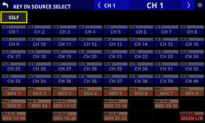
NOTE
When the DYNAMICS TYPE is Comp, the KEY IN SOURCE is the Pre Comp signal.
When the DYNAMICS TYPE is DUCKER, the KEY IN SOURCE is the POST Fader/MUTE signal.
The following settings can be made on the MODULE (SEND/PAN) Screen.
SEND level, SEND PAN, ON/OFF, PRE/POST to MIX 1–22 buses
SEND level, ON/OFF, PRE/POST to FX 1–4 buses
PAN/BAL
MAIN L/R bus assignments
The following settings can also be made for CH 1–40 modules when Stereo Link is on, and for ST IN 1–2 and FX RTN 1–4 modules.
MODE
IMAGE
Tap the following areas for each module on the Home Screen to open this screen.
SEND/PAN button
SEND area with selection frame shown
PAN/BAL area with selection frame shown
_CH1_No(2020).jpg)
CH 1–40 modules
_CH1-2_No(2020).jpg)
CH 1–40 modules with Stereo Link on
_ST-IN_No(2020).jpg)
ST IN 1–2 modules
_FX-RTN1_No(2020).jpg)
FX RTN 1–4 module
_MIX1_No(2020).jpg)
MIX 1–22 modules
_MIX1-2_No(2020).jpg)
MIX 1–22 modules with Stereo Link on
_MAIN-LR_No(2020).jpg)
MAIN L/R Master module
SEND levels, SEND PAN and ON/OFF buttons for MIX 1–22 buses
This shows the SEND settings for MIX 1–22 buses.
Tap anywhere other than on a button to show the selection frame. When a selection frame is shown, use corresponding LCD knobs to adjust the shown SEND level and SEND PAN.
_MIX1-2_bus_No(2020).jpg)
_MIX11-12_bus_No(2020).jpg)
This shows the MIX 1–22 module label according to the display mode set for Main MODULE LABEL. In the following cases, however, the FIXED MODULE LABEL (“MIX 1”, for example) will be shown. (See “DISPLAY MODE page”.)
When the Main MODULE LABEL display mode is “FIXED”
When the Main MODULE LABEL display mode is “USER” but the USER MODULE LABEL is undefined for the corresponding MIX module
This shows the send position settings for the MIX 1–22 buses.
|
No indicator |
Set to POST FADER |
|
PRE |
Set to PRE FADER |
Use this to adjust the send levels to the MIX 1–22 buses. When a selection frame is shown, use corresponding LCD knobs (lit orange) to adjust values.
|
Assignment on |
Shown in orange |
|
Assignment off |
Shown in gray |
Range: −∞ dB – +10 dB (default: −∞ dB)
Tap this button to turn on/off signals sent to the MIX 1–22 buses.
|
Module |
default |
|
CH 1–40/ST IN 1–2/FX RTN 1–4 |
ON |
|
MIX 1–22/MAIN L/R Master |
OFF |
This adjusts the SEND PAN of the signal sent to the MIX 1–22 buses. When a selection frame is shown, use corresponding LCD knobs (lit yellow) to adjust values.
Range: L100 – C – R100 (default: C)
_MIX15-16_bus_No(2020).jpg)
Rounded buttons are shown for MIX 1–22 modules set to GROUP buses. Tap this button to turn it on and off.
NOTE
A list of SEND settings for each bus can be viewed and operated (“MIX 1–22 bus SEND OVERVIEW Screen”).
Tap the SEND level area while pressing the HOME key on the top panel to set the SEND level for that bus to 0 dB.
Tap the SEND PAN area while pressing the HOME key on the top panel to set the SEND PAN for the tapped bus to center (C).
When Stereo Link is on for a MIX 1–22 bus, the PAN status will be shown in the bus area of the lower number, and the level and button will be shown in the bus area of the higher number.
SEND PAN parameters for buses with the PAN LINK setting on appear dim. Tapping them will not select them and they cannot be operated. They are linked to the PAN/BAL setting.
When a MIX 1–22 module is selected, the SEND level and button to the same bus as the selected module are not shown.
If a MIX 1–22 bus is already assigned to the MAIN L/R bus, trying to turn this MIX button on for the MAIN L/R Master module will produce an error message. To prevent a feedback loop, it cannot be turned on.
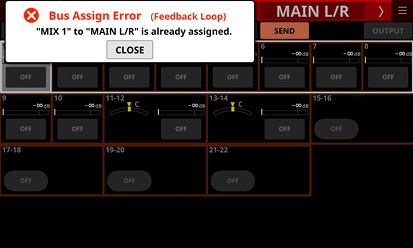
SEND levels and ON/OFF buttons for FX 1–4 buses
This shows the SEND settings for FX 1–4 buses.
Tap anywhere other than on a button to show the selection frame. When a selection frame is shown, use corresponding LCD knobs to adjust the shown SEND level.
_FX1-2_bus_No(2020).jpg)
This shows the FX RTN1–4 module label according to the display mode set for Main MODULE LABEL. In the following cases, however, the FIXED MODULE LABEL (“FX 1”, for example) will be shown. (See “DISPLAY MODE page”.)
When the Main MODULE LABEL display mode is “FIXED”
When the Main MODULE LABEL display mode is “USER” but the USER MODULE LABEL is undefined for the corresponding FX RTN module
This shows the send position setting for the FX 1–4 bus.
|
No indicator |
Set to POST FADER |
|
PRE |
Set to PRE FADER |
Use this to adjust the send level to the FX 1–4 bus. When a selection frame is shown, use corresponding LCD knobs (lit green) to adjust values.
|
Assignment on |
Shown in green |
|
Assignment off |
Shown in gray |
Range: −∞ dB – +10 dB (default: −∞ dB)
Tap this button to turn on/off the signal sent to the FX 1–4 bus.
Options: ON (default), OFF
NOTE
This is not shown when the selected module is an FX RTN 1–4 or MAIN L/R Master module.
A list of SEND settings for each bus can be viewed and operated (“FX 1–4 bus SEND OVERVIEW Screen”).
Tap the SEND level area while pressing the HOME key on the top panel to set the SEND level for that bus to 0 dB.
PRE/POST SETTINGS button
Tap this button to highlight it, changing the ON/OFF button for each bus to a PRE/POST settings button.
_PRE-POST_SETTINGS.jpg)
Tap each button to change the send positions to the MIX 1–22 and FX1–4 buses.
Options: PRE, POST (default)
NOTE
This is only shown when the selected module is a CH 1–40, ST IN 1–2 or FX RTN 1–4 module.
A list of PRE/POST settings can be viewed and operated for each bus on the PRE/POST (INPUT) Screen (See “MIX 1–22 bus SEND OVERVIEW Screen” and “FX 1–4 bus SEND OVERVIEW Screen”.)
PAN indicator (shown for mono modules only)
This adjusts the pan of the signals sent to the MAIN L/R bus.
Range: L100 – C – R100 (default: C)
When the selection frame is shown, turn LCD knob 8 (lit yellow) to adjust it.
NOTE
A list of PAN/BAL settings can be viewed and operated for the MAIN L/R bus on the SEND PAN (INPUT) and SEND PAN (BUS) screens (“MAIN L/R bus SEND OVERVIEW Screen”).
When PAN settings are centered (C), signals are reduced by 3 dB and sent to both left and right MAIN MIX L/R buses.
Tap this area while pressing the HOME key on the top panel to set the pan to center (C).
MAIN button
Tap this button to turn the assignment to the MAIN L/R bus on/off.
When this is on, the button will appear highlighted, and the signal will be sent to MAIN L/R bus.
|
Module name |
default |
|
CH 1–40 |
On |
|
ST IN 1–2 |
On |
|
FX RTN 1–4 |
On |
|
MIX 1–22 |
Off |
NOTE
A list of MAIN L/R bus assignment settings can be viewed and operated on the ON/OFF (INPUT) and ON/OFF (BUS) screens (“MAIN L/R bus SEND OVERVIEW Screen”).
This is not shown when the selected module is the MAIN L/R Master module.
If the MAIN L/R Master module is already assigned to the selected MIX 1–22 bus and on, trying to turn this button on for the MIX 1–22 module will produce the following error message. To prevent a feedback loop, it cannot be turned on.
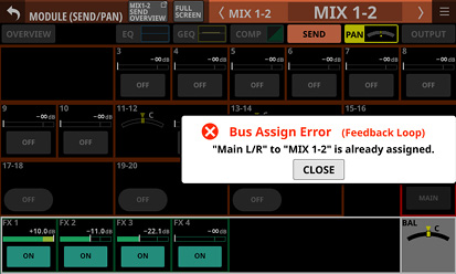
MODE
This shows the selected setting.
Tap this area to open a window where the setting can be selected to handle the stereo module input signal as a stereo signal or to handle either the left or right channel as a mono signal.
_CH1-2_pop_MONO-SW.jpg)
|
Option |
Meaning |
|
STEREO (default) |
Input the two input signals as a stereo signal to the module. |
|
L-Mono |
Input only the left signal of the two input signals as a mono signal to the module. |
|
R-Mono |
Input only the right signal of the two input signals as a mono signal to the module. |
NOTE
This is only shown when the selected module is a CH 1–40 module with the Stereo Link setting on, or a ST IN 1–2 or FX RTN 1–4 module.
If L-Mono or R-Mono is selected, the BAL setting will function as a PAN setting.
IMAGE
Use this to adjust the image width of the stereo signal.
The farthest left produces ordinary stereo. Turning it right reduces the stereo width until the center where it becomes mono. Turning it further to the right reverses the stereo positions until left and right are completely reversed at the farthest right.
Range: STEREO 100% – MONO – REVERSE 100% (default: STEREO 100%)
When the selection frame is shown, turn LCD knob 7 (lit green) to adjust it.
NOTE
This is only shown when the selected module is a CH 1–40 module with the Stereo Link setting on, or a ST IN 1–2 or FX RTN 1–4 module.
BAL indicator (shown for stereo modules only)
This adjusts the balance of the signals sent to the MAIN L/R bus.
Range: L100 – C – R100 (default: C)
When the selection frame is shown, turn LCD knob 8 (lit yellow) to adjust it.
NOTE
A list of PAN/BAL settings can be viewed and operated for the MAIN L/R bus on the SEND PAN (INPUT) and SEND PAN (BUS) Screen (“MAIN L/R bus SEND OVERVIEW Screen”).
This is not shown when the selected module is the MAIN L/R Master module.
When BAL settings are centered (C), the left channel is sent to the MAIN L bus and the right channel is sent to the MAIN R bus at 0 dB.
Tap this area while pressing the HOME key on the top panel to set the balance to center (C).
Module output settings can be made on the MODULE (OUTPUT) Screens for MIX 1–22 and MAIN L/R Master modules.
Tap the OUTPUT area at the top of the Home Screen of a MIX 1–22 or MAIN L/R Master module to open this screen.
_MIX1_No(2025).jpg)
MIX 1–22 modules
_MIX1-2_No(2025).jpg)
MIX 1–22 modules with Stereo Link on
_MAIN-LR_No(2025).jpg)
MAIN L/R Master module
PRE FADER level meter(s)
This shows PRE FADER signal level(s).
LOCK/UNLOCK button
This button locks/unlocks routing setting change operations for the unit. This is always locked at the time of start up.
When locked, operation of the BATCH SETUP button is not possible. However, tapping the OUTPUT PORT SELECT area () and switching to the OUTPUT PORT SELECT Screen is possible.
When set to “LOCK”, tap this button to open a confirmation message. Tap the UNLOCK button to close the message and set it to “UNLOCK”. Tapping the CANCEL button on the confirmation message will close it and maintain the locked state.
Tap this button when set to “UNLOCK” to switch it to “LOCK”.
NOTE
The LOCK/UNLOCK button () setting is shared by the following routing setting screens.
MODULE (INPUT) Screen
MODULE (OUTPUT) Screen
INPUT SOURCE SELECT Screen
OUTPUT PORT SELECT Screen
DIRECT OUT PORT SELECT Screen
INSERT SEND PORT SELECT Screen
INSERT RETURN PORT SELECT Screen
TALKBACK INPUT SELECT Screen
TALKBACK EXT1 DIRECT OUT PORT SELECT Screen
TALKBACK EXT2 DIRECT OUT PORT SELECT Screen
Return TALKBACK EXT DIRECT OUT PORT SELECT Screen
MONITOR 1 DIRECT OUT PORT SELECT Screen
MONITOR 2 DIRECT OUT PORT SELECT Screen
MONITOR 2 OUTPUT PORT SELECT Screen
Solo DIRECT OUT PORT SELECT Screen
Routing Screen
OUTPUT PORT SELECT area
This area shows the output ports that the signal of the selected module is assigned to.
The first line shows an abbreviation of the FIXED PORT LABEL.
The second line shows the USER PORT LABEL.
If the USER PORT LABEL is undefined, the FIXED PORT LABEL will be shown.
Up to 32 ports can be shown for mono modules.
Up to 16 ports can be shown for each stereo module.
If the number of assigned output ports exceeds the above, “…” will be shown at the bottom right of the area.
Tap this area to open the OUTPUT PORT SELECT Screen that has the tapped output port. (See “OUTPUT PORT SELECT screen”.)
If Dante ports that have mounted SB-16Ds assigned are selected, they will be shown as follows.
1st line: DA port number
2nd line: SB #[ID] port number
3rd line: USER PORT LABEL or SB #[ID] port number (if the USER PORT LABEL is undefined)
![]()
Assigned buttons for Dante ports that have virtually-mounted SB-16Ds will be highlighted yellow.
![]()
When multiple output ports are assigned to the module, this button switches to a mode for selecting just one to be shown as the PORT LABEL.
Tap this button to switch to SELECT PORT LABEL mode.
_MIX1_pop_SELECT-PORT-LABEL.jpg)
Tap the button for the desired output port to select it for showing as the PORT LABEL.
The selected output port button will have a white frame.
By default, no port will be selected with the SELECT PORT LABEL mode. In this case, the output port shown at the top left of the OUTPUT PORT SELECT area () will be shown as the PORT LABEL.
If multiple output ports are not assigned to the module, this button will appear dimmed.
POST FADER level meter(s)
This shows POST FADER signal level(s).
BATCH SETUP button
When the LOCK/UNLOCK button () is set to “UNLOCK”, tap this button to open a BATCH SETUP window where the output ports of a range of channels can be set at the same time. (See “Setting output ports for multiple channels at the same time in batches”.)
Change settings for multiple designated channels at the same time.
Phase button(s)
Use these to change the phases of the signals for the selected module.
Tap these buttons to reverse the phases of the selected module signals.
Phase button display when the Stereo Link setting is off for the selected module
|
|
Normal |
|
|
Reversed |
Phase button display when the selected module is stereo
|
|
Normal |
|
|
Reversed |
LABEL setting area
_LABEL_No(2024).jpg)
LABEL setting area ![]() icon
icon
Tap this icon to open the DISPLAY MODE page of the LABEL SETUP Screen. (See “DISPLAY MODE page”.)
MODULE LABEL display mode setting button
This button switches the Main MODULE LABEL display mode. The current display mode appears highlighted.
Tap this button to cycle through the Main MODULE LABEL display modes in order: USER, FIXED, PORT LABEL.
See “DISPLAY MODE page” for details about Main MODULE LABEL display mode settings.
PORT LABEL display mode setting button
This button switches the PORT LABEL (input/output port name) display mode. The current display mode appears highlighted.
Tap this button to alternate the PORT LABEL display mode between “USER” and “FIXED”.
See “DISPLAY MODE page” for details about PORT LABEL display mode settings.
Stereo Link button (MIX 1–22 modules only)
These show the stereo link setting states of the MIX 1–22 modules.
|
|
Stereo linking is off |
|
|
Stereo linking is on |
Tap this button to open the Stereo Link setting window.
_MIX2_pop_StereoLink.jpg)
Linking with either module to the left or right is possible except for MIX 1 and MIX 22.
ROUTING button
Tap this button to open the OUTPUT MODULE page of the Routing Screen. (See “OUTPUT MODULE page”.)
MODULE (Audio Follow Video) Screen
The Audio Follow Video (AFV) function can be considered as a “tally linking function” that automatically controls fader levels in response to external tally input events.
Use this screen to set AFV parameters for the selected module.
Tap any of the following to open this screen.
AFV button on the MODULE (OVERVIEW) Screen
Selection frame when it is on the AFV parameter on the Home Screen
_CH1_AFV-On_No(2024).jpg)
Appearance when the ON/OFF button for the entire Audio Follow Video function is ON
ON/OFF button for the Audio Follow Video function of the selected module
Tap this button to turn on/off the Audio Follow Video function of the selected module.
When ON, buttons will be highlighted.
Audio Follow Video function TRIGGER SOURCE area
This shows the AFV TRIGGER SOURCE of the selected module.
When AFV TRIGGER is active, this area will be highlighted red.
Tap this area to open the AFV TRIGGER SOURCE SELECT Screen. (See “AFV TRIGGER SOURCE SELECT Screen”.)
This shows the name of the AFV TRIGGER SOURCE selected on the AFV TRIGGER SOURCE SELECT Screen.
TEST button
Use this button to test the operation of the Audio Follow Video function of the selected module alone.
Pressing this button will function as receiving an AFV ON event, while releasing this button will function as receiving an AFV OFF event.
ON/OFF button for the entire Audio Follow Video function
Tap this button to turn on/off the entire Audio Follow Video function.
When ON, buttons will be highlighted.
When off, all AFV parameters for all modules will appear gray.
Audio Follow Video function setting status graph
This graph illustrates the automatic fader level operation using the current AFV parameter settings. The vertical axis shows the FADER level and the horizontal axis shows the time.
ON LEVEL
This adjusts the fade target value of the fader level after an AFV ON event is received.
Range: −∞ dB – +10.0 dB (default: 0.00 dB)
Turn LCD knob 1 (lit white) to adjust it.
OFF LEVEL
This adjusts the fade target value of the fader level after an AFV OFF event is received.
Range: −∞ dB – +10.0 dB (default: −∞ dB)
Turn LCD knob 2 (lit blue) to adjust it.
WAIT TIME
This adjusts the amount of time until fading starts after receiving an AFV ON event.
Range: 0.0 – 10.0 sec (default: 0.0 sec)
Turn LCD knob 3 (lit green) to adjust it.
RISE TIME
This adjusts the amount of fade time until the ON LEVEL is reached after fading starts when an AFV ON event is received.
Range: 0.0 – 10.0 sec (default: 1.0 sec)
Turn LCD knob 4 (lit yellow) to adjust it.
HOLD TIME
This adjusts the amount of time until fading starts after receiving an AFV OFF event.
Range: 0.0 – 10.0 sec (default: 1.0 sec)
Turn LCD knob 6 (lit red) to adjust it.
FALL TIME
This adjusts the amount of fade time until the OFF LEVEL is reached after fading starts when an AFV OFF event is received.
Range: 0.0 – 10.0 sec (default: 1.0 sec)
Turn LCD knob 7 (lit light blue) to adjust it.
NOTE
If any of the following operations are conducted during a fade operation caused by the Audio Follow Video function, the fade operation will be canceled.
All System Data Loading
Snapshot Recall
Module Library Recall
FADER LEVEL operation of the corresponding module on the MODULE (OVERVIEW) Screen
FADER LEVEL operation of the corresponding module on the FADER LEVEL page of the SEND OVERVIEW (MAIN L/R) Screen
AFV TRIGGER SOURCE SELECT Screen
The AFV TRIGGER SOURCE of the selected module can be selected from the following on this screen.
GPIO input connector of this unit
GPIO input connector of a mounted SB-16D connected through the built-in Dante
Rear panel FOOTSWITCH jack
To open this screen, tap the Audio Follow Video function TRIGGER SOURCE area () on the MODULE (Audio Follow Video) Screen.
.jpg)
Audio Follow Video function TRIGGER SOURCE selection buttons
Tap these buttons to select the AFV TRIGGER SOURCE of the selected module.
Selected buttons will be highlighted.
User Defined Control functions assigned to a corresponding GPIO-IN/footswitch are shown in the ranks below the buttons.
Checking whether multiple functions have been assigned to an item is possible.
A ![]() mark will appear for virtually-mounted SB-16D GPIO-IN ports.
mark will appear for virtually-mounted SB-16D GPIO-IN ports.
![]()
Assigned buttons for virtually-mounted SB-16D GPIO-IN ports will be highlighted yellow.
![]()
MODULE menu operations
Tap the ![]() button at the top right of the MODULE screen to open the MODULE menu for the selected module.
button at the top right of the MODULE screen to open the MODULE menu for the selected module.
Scrollbars appear when all selectable items cannot be shown in the MODULE menu at the same time. In this case, drag the menu up and down to scroll the items.
Tap the MODULE menu ![]() button or the
button or the ![]() button to close the menu.
button to close the menu.
MODULE menu items
|
Menu item |
Function |
|
Copy MODULE |
This copies all the parameter setting values of the selected module into a buffer. |
|
Paste MODULE |
This pastes all the parameter setting values copied into the buffer to the selected module. |
|
UNDO Paste MODULE |
This undoes pasting to the selected module. |
|
REDO Paste MODULE |
This redoes pasting to the selected module. |
|
Copy INPUT |
This copies all the parameter setting values on the MODULE (INPUT) Screen of the selected module into a buffer. |
|
Paste INPUT |
This pastes all the MODULE (INPUT) Screen parameter setting values copied into the buffer to the selected module. |
|
UNDO Paste INPUT |
This undoes pasting to the MODULE (INPUT) Screen of the selected module. |
|
REDO Paste INPUT |
This redoes pasting to the MODULE (INPUT) Screen of the selected module. |
|
MODULE Library |
Tap this area to open the LIBRARY Screen for the selected module. (See “Various LIBRARY Screens”.) |
NOTE
The underlined words in the menu item list will be replaced with the MODULE screen names of the selected module.
The menu items with underlined words are not shown on the MODULE (OVERVIEW) and MODULE (OUTPUT) screens.
The following parameters cannot be copied or pasted.
Input Routing
OSC Input
Output Port Assign*
Insert Send Port Assign*
Insert Return Port Assign*
Insert ON/OFF*
Direct Out Port Assign*
*Output ports cannot be used by multiple modules at the same time. These parameters are excluded from copying and pasting because doing so would change the output settings of other modules along with the paste destination.
Pasting parameters that can be operated independently for left and right in stereo modules
The following parameters can be set independently for left and right channels even in stereo modules.
Pre Amp
Phase
D.TRIM
If the mono/stereo states of the copy source and paste destinations are different, copying and pasting will occur as follows.
If the copy source is a mono module and the paste destination is a stereo module, the copy source setting data will be pasted to both L and R of the paste destination.
If the copy source is a stereo module and the paste destination is a mono module, the L channel setting data of the copy source will be pasted to the paste destination.
Pasting MODE/IMAGE parameters
MODE/IMAGE parameters shown on the MODULE (SEND/PAN) screen only exist for stereo input modules. (See “MODULE (SEND/PAN) Screen”.)
For this reason, MODE/IMAGE parameters can only be copied and pasted when both the source and destination are stereo input modules.
The SENDS ON FADER function enables controlling SEND levels with faders.
When in Sends On Fader mode, the SENDS ON FADER on the top panel lights and the following operations are possible.
Using channel faders to control SEND levels from each module to buses subject to SENDS ON FADER operation
Using the MASTER fader to control the FADER level (bus master level) of buses subject to SENDS ON FADER operation
Using channel MUTE keys to switch SEND ON/OFF to buses subject to SENDS ON FADER operation from each module (MUTE key lit: SEND OFF, MUTE key unlit: SEND ON)
In addition, the MUTE, SOLO and SEL keys and the color bar in the top panel master section will become operation keys and displays for the bus subject to SENDS ON FADER operation. The SEND indicator will also light and the L/R indicators will become unlit.
Sends On Fader mode can be activated and deactivated with the following operations.
Top panel SENDS ON FADER key
USER KEYS/FOOTSWITCH/GPIO-IN assigned to the Sends On Fader function (See “USER DEFINED CONTROLS screen”.)
NOTE
The Sends On Fader mode setting is assigned to the following USER KEYS by default on the User Key page.
USER KEYS 5–12 (Sends On Fader | MIX1–8)
Select the buses subject to SENDS ON FADER operation on this screen.
Press the SENDS ON FADER key on the top panel to open this screen.
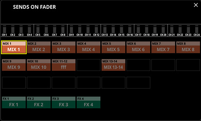
NOTE
The meters shown at the top of the SENDS ON FADER Screen enable checking the module meters (which show signal levels at set Metering Points) of modules assigned to the selected layer. (See “ Channel screen”.)
Tap a bus selection button, highlighting it, to select that bus. The channel faders will move to the positions of the SEND levels from the modules to the selected buses. The MASTER fader will move to the position of the FADER level of the selected bus. The channel MUTE keys will be lit/unlit according to the SEND ON/OFF status to the selected bus of each module (MUTE key lit: SEND OFF, MUTE key unlit: SEND ON).
To use SENDS ON FADER operation while, for example, the Home Screen on the right touchscreen is open, tap the ![]() icon at the top right of this screen to close it.
icon at the top right of this screen to close it.
Tapping the ![]() icon will close this window, but Sends On Fader mode will remain active. Press the SENDS ON FADER key to open the SENDS ON FADER Screen again.
icon will close this window, but Sends On Fader mode will remain active. Press the SENDS ON FADER key to open the SENDS ON FADER Screen again.
Press SENDS ON FADER key when the SENDS ON FADER screen is open to end Sends On Fader mode. This will close the SENDS ON FADER screen and return these items to their normal display states: channel faders and mute buttons, MASTER faders, master section MUTE, SOLO and SEL keys and color bars, L/R SEND indicators and channel screens.
When Sends On Fader mode is active, similar meters will also be shown in the CH Display.
NOTE
This screen will not be shown for a MIX bus with BUS mode set to GROUP.
SEND parameters for the selected bus (MIX 1–22, FX 1–4 or MAIN L/R) are shown in a list and can be operated.
The MODULE (SEND/PAN) Screen shows a list of the SEND parameters () aligned vertically on the analog mixer, and can be used to operate them.
In contrast, the SEND OVERVIEW Screen shows a list of the SEND parameters () aligned horizontally on the analog mixer, and can be used to operate them.
.jpg)
MIX 1–22 bus SEND OVERVIEW Screen
Tap Menu Screen > Mixer Setup menu> MIX Send Overview to open this screen. The SEND OVERVIEW button at the top of the MODULE Screen for a MIX 1–22 module can also be tapped to open this screen.
.jpg)
SEND LEVEL (INPUT) page
.jpg)
SEND LEVEL (BUS) page
.jpg)
ON/OFF (INPUT) page
.jpg)
ON/OFF (BUS) page
.jpg)
PRE/POST (INPUT) page
.jpg)
SEND PAN (INPUT) page
.jpg)
SEND PAN (BUS) page
.jpg)
ON/OFF (INPUT) page (GROUP mode bus)
.jpg)
ON/OFF (BUS) page (GROUP mode bus)
NOTE
Tap a level while pressing the HOME key on the top panel to set that level to 0 dB.
Tap a PAN/BAL indicator while pressing the HOME key to set the tapped pan/balance setting to center (C).
![]() button
button
Tap this button to return to the screen shown before the SEND OVERVIEW Screen.
MODULE button
Tap this button to open the MODULE Screen for the selected MIX 1–22 module.
![]() /
/![]() buttons
buttons
Tap these buttons to move left and right in order between MIX 1–22, FX 1–4 and MAIN L/R buses to show and activate them for operation.
FIXED MODULE LABEL
This shows the FIXED MODULE LABEL of the selected bus.
USER MODULE LABEL
This shows the module label according to the display mode set for the Main MODULE LABEL of the selected bus. (See “DISPLAY MODE page”.)
Tap this area when the Main MODULE LABEL display mode is set to “USER” to open the MODULE LABEL Screen where the user module label and set module color can be changed. (See “MODULE LABEL page”.)
If the Main MODULE LABEL display mode is set to “PORT LABEL” and the PORT LABEL display mode is set to “USER” (See “DISPLAY MODE page”.), tapping this area will open the USER LABEL (OUTPUT PORT) Screen where the user port label can be edited for the output port assigned to this module. (See “USER LABEL (INPUT PORT / OUTPUT PORT) Screen”.)
No screen will open, however, if no output port has been assigned to the module.
![]() button
button
Tap this button to open the SEND OVERVIEW menu for the selected MIX 1–22 bus.
_pop_Menu.jpg)
Tap menu items to change parameter settings for the selected MIX 1–22 buses. (See “SEND OVERVIEW menu”.)
Page selection buttons
Tap a page selection button to open that page.
The selected button will be highlighted.
|
Button |
Use |
|---|---|
|
SEND LEVEL (INPUT) |
This shows a list of SEND levels from the CH 1–40, ST IN 1–2 and FX RTN 1–4 modules to the MIX 1–22 buses. |
|
SEND LEVEL (BUS) |
This shows a list of SEND levels from the MIX 1–22 and MAIN L/R Master modules to the MIX 1–22 buses. |
|
ON / OFF (INPUT) |
This shows a list of assignment on/off states from the CH 1–40, ST IN 1–2 and FX RTN 1–4 modules to the MIX 1–22 buses. |
|
ON / OFF (BUS) |
This shows a list of assignment on/off states from the MIX 1–22 and MAIN L/R Master modules to the MIX 1–22 buses. |
|
PRE / POST (INPUT) |
This shows a list of signal send positions from the CH 1–40, ST IN 1–2 and FX RTN 1–4 modules to the MIX 1–22 buses. |
|
SEND PAN (INPUT) |
This shows a list of pan/balance settings from the CH 1–40, ST IN 1–2 and FX RTN 1–4 modules to the MIX 1–22 buses. |
|
SEND PAN (BUS) |
This shows a list of pan/balance settings from the MIX 1–22 modules to the MIX 1–22 buses. |
SEND levels
This shows a list of setting states for SEND levels from the CH 1–40, ST IN 1–2 and FX RTN 1–4 modules to the MIX 1–22 buses.
When a selection frame is shown, use corresponding LCD knobs (lit orange) to adjust SEND levels.
Range: −∞ dB – +10 dB (default: −∞ dB)
CH MUTE / PRE-SEND LINK
Set separately for each bus whether or not input module MUTE and Pre Fader Send MUTE from the input module to the AUX bus are linked.
Tap this button to switch the setting between LINK and UNLINK.
|
Display |
Explanation |
|
LINK (default) |
Input module MUTE and Pre Fader Send MUTE from the input module to the AUX bus are linked |
|
UNLINK |
Input module MUTE and Pre Fader Send MUTE from the input module to the AUX bus are not linked |
MIX MASTER LEVEL
This adjusts the FADER level (bus master level) for the selected MIX 1–22 bus.
Range: −∞ dB – +10 dB (default: 0.0 dB)
When the selection frame is shown, turn LCD knob 8 (lit blue) to adjust it.
SEND levels
This shows a list of setting states for SEND levels from the MIX 1–22 and MAIN L/R Master modules to the MIX 1–22 buses.
When a selection frame is shown, use corresponding LCD knobs (lit orange) to adjust SEND levels.
Range: −∞ dB – +10 dB (default: −∞ dB)
NOTE
SEND levels to the same bus as the selected bus shown in the USER MODULE LABEL area () will not be shown.
Input module ON/OFF buttons
This shows a list of assignment ON/OFF states from the CH 1–40, ST IN 1–2 and FX RTN 1–4 modules to the MIX 1–22 buses.
Tap these buttons to switch on/off assignments to MIX 1–22 buses. (Default: ON)
When ON, buttons will be highlighted.
BUS module ON/OFF buttons
This shows a list of assignment ON/OFF states from the MIX 1–22 and MAIN L/R Master modules to the MIX 1–22 buses.
Tap these buttons to switch on/off assignments to MIX 1–22 buses. (Default: OFF)
When ON, buttons will be highlighted.
NOTE
An assignment button for the same bus as the selected bus shown in the USER MODULE LABEL area () will not be shown.
PRE/POST buttons
This shows a list of settings for send positions from the CH 1–40, ST IN 1–2 and FX RTN 1–4 modules to the MIX 1–22 buses.
Tap these buttons to switch settings for send positions to MIX 1–22 buses. (See “19 - Block diagram”.)
|
Display |
Explanation |
|
PRE |
Pre-fader |
|
POST (default) |
Post-fader |
Tap the buttons to switch their send positions.
PAN/BAL for CH 1–40, ST IN 1–2 and FX RTN 1–4 modules
This shows a list of setting states for pan/balance from the CH 1–40, ST IN 1–2 and FX RTN 1–4 modules to the selected MIX 1–22 buses.
When a selection frame is shown, use corresponding LCD knobs (lit yellow) to adjust the pan/balance.
Range: L100 – C – R100 (default: C)
NOTE
For buses that have the PAN LINK setting on, the SEND PAN parameters appear dim and cannot be operated. They are linked to the PAN/BAL settings of the corresponding modules.
MIX 1–22 module PAN/BAL
This shows a list of setting states for pan/balance from the MIX 1–22 modules to the selected MIX 1–22 bus.
When a selection frame is shown, use corresponding LCD knobs (lit yellow) to adjust the pan/balance.
Range: L100 – C – R100 (default: C)
NOTE
For buses that have the PAN LINK setting on, the SEND PAN parameters appear dim and cannot be operated. They are linked to the PAN/BAL settings of the corresponding modules.
FX 1–4 bus SEND OVERVIEW Screen
Tap Menu Screen > Mixer Setup menu> MIX Send Overview to open this screen. The SEND OVERVIEW button at the top of the MODULE Screen for a FX RTN 1–4 module can also be tapped to open this screen.
.jpg)
SEND LEVEL (INPUT) page
.jpg)
SEND LEVEL (BUS) page
.jpg)
ON/OFF (INPUT) page
.jpg)
ON/OFF (BUS) page
.jpg)
PRE/POST (INPUT) page
.jpg)
SEND PAN (INPUT) page
.jpg)
SEND PAN (BUS) page
NOTE
Tap a level while pressing the HOME key on the top panel to set that level to 0 dB.
![]() button
button
Tap this button to return to the screen shown before the SEND OVERVIEW Screen.
MODULE button
Tap this button to open the MODULE Screen for the FX RTN 1–4 module that corresponds to the FX 1–4 bus shown.
![]() /
/![]() buttons
buttons
Tap these buttons to move left and right in order between MIX 1–22, FX 1–4 and MAIN L/R buses to show and activate them for operation.
FIXED MODULE LABEL
This shows the FIXED MODULE LABEL of the selected bus.
USER MODULE LABEL
This shows the module label according to the display mode set for the Main MODULE LABEL of the selected bus. (See “DISPLAY MODE page”.)
Tap this area when the Main MODULE LABEL display mode is set to “USER” to open the MODULE LABEL Screen where the user module label and set module color can be changed. (See “MODULE LABEL screen”.)
![]() button
button
Tap this button to open the SEND OVERVIEW menu for the selected FX 1–4 bus.
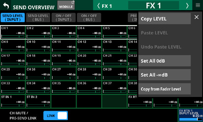
Tap menu items to change parameter settings for the selected FX 1–4 buses. (See “SEND OVERVIEW menu”.)
Page selection buttons
Tap a page selection button to open that page.
The selected button will be highlighted.
|
Button |
Use |
|
SEND LEVEL (INPUT) |
This shows a list of SEND levels from the CH 1–40 and ST IN 1–2 modules to the FX 1–4 buses. |
|
SEND LEVEL (BUS) |
This shows a list of SEND levels from the MIX 1–22 modules to the FX 1–4 buses. |
|
ON / OFF (INPUT) |
This shows a list of assignment on/off states from the CH 1–40 and ST IN 1–2 modules to the FX 1–4 buses. |
|
ON / OFF (BUS) |
This shows a list of assignment on/off states from the MIX 1–22 modules to the FX 1–4 buses. |
|
PRE / POST (INPUT) |
This shows a list of signal send positions from the CH 1–40 and ST IN 1–2 modules to the FX 1–4 buses. |
|
SEND PAN (INPUT) |
This shows a list of pan/balance settings from the CH 1–40 and ST IN 1–2 modules to the FX 1–4 buses. |
|
SEND PAN (BUS) |
This shows a list of pan/balance settings from the MIX 1–22 modules to the FX 1–4 buses. |
SEND levels
This shows a list of setting states for SEND levels from the CH 1–40, ST IN 1–2 and FX RTN 1–4 modules to the FX 1–4 buses.
When a selection frame is shown, use corresponding LCD knobs (lit green) to adjust SEND levels.
Range: −∞ dB – +10 dB (default: −∞ dB)
CH MUTE / PRE-SEND LINK
Set separately for each bus whether or not input module MUTE and Pre Fader Send MUTE from the input module to the AUX bus are linked.
Tap this button to switch the setting between LINK and UNLINK.
|
Display |
Explanation |
|
LINK (default) |
Input module MUTE and Pre Fader Send MUTE from the input module to the AUX bus are linked |
|
UNLINK |
Input module MUTE and Pre Fader Send MUTE from the input module to the AUX bus are not linked |
FX INPUT LEVEL
This adjusts the input level for the FX 1–4 module that corresponds to the FX 1–4 bus shown.
Range: −∞ dB – +10 dB (default: 0.0 dB)
When the selection frame is shown, turn LCD knob 8 (lit blue) to adjust it.
NOTE
This is the same parameter as the FX RTN 1–4 module INPUT LEVEL knob () (“MODULE (FX) Screen”).
SEND levels
This shows a list of setting states for SEND levels from the MIX 1–22 modules to the FX 1–4 buses.
When a selection frame is shown, use corresponding LCD knobs (lit green) to adjust SEND levels.
Range: −∞ dB – +10 dB (default: −∞ dB)
Input module ON/OFF buttons
This shows a list of assignment ON/OFF states from the CH 1–40, ST IN 1–2 and FX RTN 1–4 modules to the FX 1–4 buses.
Tap these buttons to switch on/off assignments to FX 1–4 buses. (Default: ON)
When ON, buttons will be highlighted.
BUS module ON/OFF buttons
This shows a list of assignment on/off states from the MIX 1–22 modules to the FX 1–4 buses.
Tap these buttons to switch on/off assignments to FX 1–4 buses. (Default: ON)
When ON, buttons will be highlighted.
PRE/POST buttons
This shows a list of settings for send positions from the CH 1–40, ST IN 1–2 and FX RTN 1–4 modules to the FX 1–4 buses.
Tap these buttons to switch settings for send positions to FX 1–4 buses. (See “19 - Block diagram”.)
|
Display |
Explanation |
|
PRE |
Pre-fader |
|
POST (default) |
Post-fader |
Tap the buttons to switch their send positions.
PAN/BAL for CH 1–40 and ST IN 1–2 modules
This shows a list of setting states for pan/balance from the CH 1–40, ST IN 1–2 and FX RTN 1–4 modules to the selected FX 1–4 buses.
Display range: L100 – C – R100 (default: C)
NOTE
FX 1–4 bus SEND PAN parameters are always linked to the PAN/BAL settings of the corresponding modules (PAN LINK setting is always on). They are shown dimly and cannot be operated on this screen.
MIX 1–22 module PAN/BAL
This shows a list of setting states for pan/balance from the MIX 1–22 modules to the selected FX 1–4 bus.
Display range: L100 – C – R100 (default: C)
NOTE
FX 1–4 bus SEND PAN parameters are always linked to the PAN/BAL settings of the corresponding modules (PAN LINK setting is always on). They are shown dimly and cannot be operated on this screen.
MAIN L/R bus SEND OVERVIEW Screen
Tap Menu Screen > Mixer Setup menu> MIX Send Overview to open this screen. The SEND OVERVIEW button at the top of the MODULE Screen for the MAIN L/R Master module can also be tapped to open this screen.
.jpg)
FADER LEVEL (INPUT) page
.jpg)
FADER LEVEL (BUS) page
.jpg)
ON/OFF (INPUT) page
.jpg)
ON/OFF (BUS) page
.jpg)
SEND/PAN (INPUT) page
.jpg)
SEND/PAN (BUS) page
NOTE
Tap a level while pressing the HOME key on the top panel to set that level to 0 dB.
Tap a PAN/BAL indicator while pressing the HOME key to set the tapped pan/balance setting to center (C).
![]() button
button
Tap this button to return to the screen shown before the SEND OVERVIEW Screen.
MODULE button
Tap this button to open the MODULE Screen for the selected MAIN L/R Master module.
![]() /
/![]() buttons
buttons
Tap these buttons to move left and right in order between MIX 1–22, FX 1–4 and MAIN L/R buses to show and activate them for operation.
FIXED MODULE LABEL
This shows the FIXED MODULE LABEL of the selected bus.
USER MODULE LABEL
This shows the module label according to the display mode set for the Main MODULE LABEL of the MAIN L/R bus. (See “DISPLAY MODE page”.)
Tap this area when the Main MODULE LABEL display mode is set to “USER” to open the MODULE LABEL Screen where the user module label and set module color can be changed. (See “MODULE LABEL screen”.)
If the Main MODULE LABEL display mode is set to “PORT LABEL” and the PORT LABEL display mode is set to “USER” (See “DISPLAY MODE page”.), tapping this area will open the USER LABEL (OUTPUT PORT) Screen where the user port label can be edited for the output port assigned to this module. (See “USER LABEL (INPUT PORT / OUTPUT PORT) Screen”.)
No screen will open, however, if no output port has been assigned to the module.
![]() button
button
Tap this button to open the SEND OVERVIEW menu for the MAIN L/R bus.
_pop_Menu.jpg)
Tap menu items to change parameter settings for the MAIN L/R bus. (See “SEND OVERVIEW menu”.)
Page selection buttons
Tap a page selection button to open that page.
The selected button will be highlighted.
|
Button |
Use |
|
FADER LEVEL (INPUT) |
This shows a list of FADER levels for the CH 1–40, ST IN 1–2 and FX RTN 1–4 modules. |
|
FADER LEVEL (BUS) |
This shows a list of FADER levels for the MIX 1–22 modules. |
|
ON / OFF (INPUT) |
This shows a list of assignment on/off states from the CH 1–40, ST IN 1–2 and FX RTN 1–4 modules to the MAIN L/R bus. |
|
ON / OFF (BUS) |
This shows a list of assignment on/off states from the MIX 1–22 modules to the MAIN L/R bus. |
|
SEND PAN (INPUT) |
This shows a list of pan/balance settings from the CH 1–40, ST IN 1–2 and FX RTN 1–4 modules to the MAIN L/R bus. |
|
SEND PAN (BUS) |
This shows a list of pan/balance settings from the MIX 1–22 modules to the MAIN L/R bus. |
FADER levels
This shows a list of FADER level setting states for the CH 1–40, ST IN 1–2 and FX RTN 1–4 modules.
When a selection frame is shown, use corresponding LCD knobs (lit blue) to adjust FADER levels.
|
Module name |
Range |
default |
|
CH 1–40 |
−∞ dB – +10 dB |
−∞ dB |
|
ST IN 1–2 |
||
|
FX RTN 1–4 |
0.0 dB |
MAIN L/R MASTER LEVEL
This adjusts the FADER level of the MAIN L/R Master module.
Range: −∞ dB – +10 dB (default: 0.0 dB)
When the selection frame is shown, turn LCD knob 8 (lit blue) to adjust it.
FADER levels
This shows a list of FADER level setting states for the MIX 1–22 modules.
When a selection frame is shown, use corresponding LCD knobs (lit blue) to adjust FADER levels.
Range: −∞ dB – +10 dB (default: 0.0 dB)
MAIN L/R assignment state indicators/buttons for input modules
This shows a list of assignment on/off states from the CH 1–40, ST IN 1–2 and FX RTN 1–4 modules to the MAIN L/R bus.
Tap these buttons to turn on/off assignments to the MAIN L/R bus.
Options: on (default), off
When this is on, the button will appear highlighted.
MAIN L/R assignment state indicators/buttons for BUS modules
This shows a list of assignment on/off states from the MIX 1–22 modules to the MAIN L/R bus.
Tap these buttons to turn on/off assignments to the MAIN L/R bus.
Options: on, off (default)
When this is on, the button will appear highlighted.
PAN/BAL for CH 1–40, ST IN 1–2 and FX RTN 1–4 modules
This shows a list of setting states for pan/balance from the CH 1–40, ST IN 1–2 and FX RTN 1–4 modules to the MAIN L/R bus.
When a selection frame is shown, use corresponding LCD knobs (lit yellow) to adjust the pan/balance.
Range: L100 – C – R100 (default: C)
MIX 1–22 module PAN/BAL
This shows a list of setting states for pan/balance from the MIX 1–22 modules to the MAIN L/R bus.
When a selection frame is shown, use corresponding LCD knobs (lit yellow) to adjust the pan/balance.
Range: L100 – C – R100 (default: C)
SEND OVERVIEW menu operations
Tap the ![]() button at the top right of the SEND OVERVIEW screen to open the SEND OVERVIEW menu for the selected bus.
button at the top right of the SEND OVERVIEW screen to open the SEND OVERVIEW menu for the selected bus.
Tap menu items to change parameter settings for the selected bus all at once.
Tap the SEND OVERVIEW menu ![]() button or the
button or the ![]() button to close the menu.
button to close the menu.
SEND OVERVIEW menu items
SEND LEVEL (INPUT), SEND LEVEL (BUS) and FADER LEVEL (INPUT)
|
Menu item |
Function |
|
Copy LEVEL |
This copies the SEND level to the selected bus to a buffer. |
|
Paste LEVEL |
This pastes the SEND level copied to the buffer to the selected bus. |
|
Undo Paste LEVEL |
This undoes pasting the SEND level. |
|
Redo Paste LEVEL |
This redoes pasting the SEND level. |
|
Set All 0dB |
This sets all the SEND levels to the selected bus to 0 dB. |
|
Set All −∞dB |
This sets all the SEND levels to the selected bus to −∞ dB. |
|
Copy from Fader Level |
This copies the FADER level to the SEND level to the selected bus. |
NOTE
When the selected bus is MAIN L/R, this will change the FADER level setting.
When the selected bus is MAIN L/R, the “Copy from Fader Level” menu item will not be shown.
ON/OFF (INPUT) and ON/OFF (BUS)
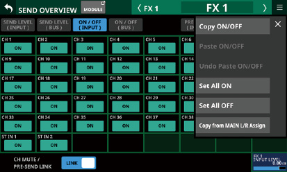
_pop_Menu.jpg)
|
Menu item |
Function |
|---|---|
|
Copy ON/OFF |
This copies the assignment settings of the selected bus to a buffer. |
|
Paste ON/OFF |
This pastes the assignment settings to the selected bus that were copied to the buffer to the selected bus. |
|
Undo Paste ON/OFF |
This undoes the pasting of assignment settings to the selected bus. |
|
Redo Paste ON/OFF |
This redoes pasting of assignment settings to the selected bus. |
|
Set All ON |
This turns on all assignment settings to the selected bus. |
|
Set All OFF |
This turns off all assignment settings to the selected bus. |
|
Copy from MAIN L/R Assign |
This copies the MAIN L/R bus assignment settings to the selected bus assignment settings. |
NOTE
When the selected bus is MAIN L/R, this will change the states of assignments to the MAIN L/R bus.
When the selected bus is MAIN L/R, the “Copy from MAIN L/R Assign” menu item will not be shown.
PRE / POST (INPUT)
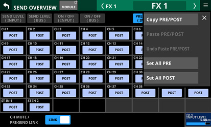
|
Menu item |
Function |
|
Copy PRE/POST |
This copies the PRE/POST settings to the selected bus to a buffer. |
|
Paste PRE/POST |
This pastes the PRE/POST settings to the selected bus that were copied to the buffer to the selected bus. |
|
Undo Paste PRE/POST |
This undoes the pasting of PRE/POST settings to the selected bus. |
|
Redo Paste PRE/POST |
This redoes pasting of PRE/POST settings to the selected bus. |
|
Set All PRE |
This sets all PRE/POST settings to the selected bus to PRE. |
|
Set All POST |
This sets all PRE/POST settings to the selected bus to POST. |
SEND PAN (INPUT) and SEND PAN (BUS)
_pop_Menu.jpg)
_pop_Menu.jpg)
|
Menu item |
Function |
|
Copy PAN/BAL |
This copies the pan/balance settings to the selected bus to a buffer. |
|
Paste PAN/BAL |
This pastes the pan/balance settings to the selected bus that were copied to the buffer to the selected bus. |
|
Undo Paste PAN/BAL |
This undoes the pasting of pan/balance settings to the selected bus. |
|
Redo Paste PAN/BAL |
This redoes pasting of pan/balance settings to the selected bus. |
|
Set All PAN Center |
This sets all pan/balance settings to the selected bus to center (C). |
|
Copy from MAIN L/R PAN |
This copies the MAIN L/R bus pan/balance settings to the selected bus pan/balance settings. |
NOTE
When the selected bus is MAIN L/R, the “Copy from MAIN L/R PAN” menu item will not be shown.
This unit has 8 mute groups.
Depending on the Mute Group Priority button setting on the PREFERENCES Screen (See “PREFERENCES screen”.), if MUTE for a module was set to ON before MUTE was set to ON for the mute group, whether or not MUTE will stay ON for that module when the group MUTE is set to OFF can be set.
When the Mute Group LED Flash switch on the PREFERENCES Screen is set to ON (See “PREFERENCES screen”.), the MUTE indicators will blink for modules muted as part of a mute group.
The following can be used to operate mute groups.
Mute Group Master page
USER KEYS/FOOTSWITCH/GPIO-IN controls assigned to the Mute Group function (See “USER DEFINED CONTROLS screen”.)
NOTE
The Mute Group function is assigned to the following by default on the User Key page.
USER KEYS 1–4 (Mute | Mute Group 1–4 | Mute - LIT)
DCA (Digital Control Amplifier) functions
This unit has 8 DCAs.
A DCA enables simultaneously adjusting the levels of a group of assigned modules while maintaining the balance of their fader levels. For example, if two modules assigned to a DCA have fader levels of −10 dB and −15 dB, when the DCA module FADER level is raised 5 dB, their fader levels will increase from −10 dB to −5 dB and −15 dB to −10 dB. In this case, the physical fader positions of the assigned faders will not change.
DCA module MUTE keys function the same way as Mute Groups.
Depending on the DCA Mute Priority button setting on the PREFERENCES Screen (See “PREFERENCES screen”.), if MUTE for a module was set to ON before MUTE was set to ON for the DCA, whether or not MUTE will stay ON for that module when the DCA MUTE is set to OFF can be set.
When the Mute Group LED Flash switch on the PREFERENCES Screen is set to ON (See “PREFERENCES screen”.), the MUTE indicators will blink for modules muted due to DCA modules.
Like mute groups, DCA module SOLO keys, allow the solo state of a group of modules assigned to it to be turned on/off together.
Depending on the DCA Solo Priority button setting on the PREFERENCES Screen (See “PREFERENCES screen”.), if SOLO for a module was set to ON before SOLO was set to ON for the DCA, whether or not SOLO will stay ON for that module when the DCA MUTE is set to OFF can be set.
The SOLO indicators will blink for modules that have SOLO turned on in DCA modules.
DCAs are operated by faders and MUTE and SOLO keys assigned to DCA layers and DCA modules.
One DCA can also be assigned to another DCA (DCA assignment nesting). The following DCA assignments, however, are not possible.
Self-assignment (for example, DCA 1 cannot be assigned to DCA 1)
Assignment of a DCA that is at a higher level (For example, if DCA 1 is above DCA 2, which is above DCA 3, in the structure, DCA 1 cannot be assigned to DCA 2, and DCA 1 and DCA 2 cannot be assigned to DCA 3.)
DCA modules that cannot be assigned have frames around their module button areas ().
In this mode, module groups assigned to a DCA are lined up on the main unit, including its channel faders and Home Screens, allowing fader levels, for example, to be adjusted.
NOTE
This mode only works with a DCA that has a module group assigned.
DCA spill mode cannot be used with TASCAM Sonicview Control. This mode can only be used with the main unit.
Turning on DCA spill mode
Tap the DCA Spill button for a DCA module on the Home Screen.
Press and hold the SEL key for the corresponding DCA module.
.jpg)
Operations when DCA spill mode is on
Adjustments, including to fader levels, for the subject DCA can be made in the master section on the top panel.
Adjustments, including to fader levels, for module groups assigned to the subject DCA can be made with the channel faders and the Home Screen, for example.
Turning off DCA spill mode
Press and hold the blinking SEL key in the master section on the top panel.
Tap the DCA Spill OFF button at the top of the DCA Assign page of the DCA/Mute Group SETUP Screen. (See “DCA Assign page”.)
NOTE
Module group operations are limited to a maximum of 16 channels on Sonicview 16 models and 24 channels on Sonicview 24 models.
When DCA spill mode is on, layer key operations are disabled.
When DCA spill mode is on, only MODULE screens for modules that are assigned to the corresponding DCA can be opened.
When DCA spill mode is on, the SEL keys and channel color bars in the master section on the top panel will blink.
DCA and Mute Group settings can be made on this screen.
Use the following procedures to open this screen.
Tap Menu screen > Mixer Setup menu > DCA / Mute Group
Tap a DCA or MUTE GROUP button on the MODULE (OVERVIEW) screen
Tap a DCA assignment area on the DCA Module Home Screen
Press a USER key assigned to a MUTE Group while pressing the MENU key on the top panel
.jpg)
.jpg)
DCA buttons
These show module labels for DCAs.
The module label set for the Sub MODULE LABEL is shown at the left of the top line.
The module label set for the Main MODULE LABEL is shown in the bottom line. (See “DISPLAY MODE page”.)
Tap these buttons to select DCAs for changing assignments. Selected DCA buttons will be highlighted.
Snapshot Recall Safe button
Tap this button to enable the Snapshot Recall Safe function for the selected DCA. (Default: off)
When this is on, the button will appear highlighted.
NOTE
This can also be set on the MODULE SAFE page of the SNAPSHOT RECALL SAFE Screen. (See “MODULE SAFE page”.)
Module type selection pages
These are page buttons for module types assigned to the DCA.
Buttons selected by tapping will be highlighted.
Module buttons
These are buttons for selecting modules assigned to the selected DCA.
The module label set for the Sub MODULE LABEL is shown at the left of the top line.
The module label set for the Main MODULE LABEL is shown in the bottom line. (See “DISPLAY MODE page”.)
Tapping these buttons, highlighting them, will assign them to the DCA.
NOTE
At the top right of each button, the Mute Group assignment status is shown and the DCA assignment status is shown in the bottom line in the same way as in the MODULE LABEL area on the Home Screen. (See “ MODULE LABEL area”.)
CLEAR ALL button
Tap this button to open a message confirming whether to clear all INPUT and OUTPUT/DCA assignments to the selected DCA.
![]()
Tap OK to clear all assignments.
DCA Spill OFF button
This button is only shown when DCA spill mode is on.
Tap this button to turn off DCA spill mode.
.jpg)
.jpg)
MuteGrp buttons
These show the Mute Group module labels.
The module label set for the Sub MODULE LABEL is shown at the left of the top line.
The module label set for the Main MODULE LABEL is shown in the bottom line. (See “DISPLAY MODE page”.)
Tap these buttons to select a Mute Group for changing assignments.
The selected Mute Group button will be highlighted.
Snapshot Recall Safe button
Tap this button to enable the Snapshot Recall Safe function for the selected Mute Group. (Default: off)
When this is on, the button will appear highlighted.
Module type selection pages
These are page buttons for module types assigned to the Mute Group.
Buttons selected by tapping will be highlighted.
Module buttons
These are buttons for selecting modules assigned to the selected Mute Group.
The module label set for the Sub MODULE LABEL is shown at the left of the top line.
The module label set for the Main MODULE LABEL is shown in the bottom line. (See “DISPLAY MODE page”.)
Tapping these buttons, highlighting them, will assign them to the Mute Group.
NOTE
At the top right of each button, the Mute Group assignment status is shown and the DCA assignment status is shown in the bottom line in the same way as in the MODULE LABEL area on the Home Screen. (See “ MODULE LABEL area”.)
CLEAR ALL button
Tap this button to open a message confirming whether to clear all INPUT and OUTPUT/DCA assignments to the selected DCA.
![]()
Tap OK to clear all assignments.
.jpg)
Mute Group names
These show the Mute Group module labels.
The module label set for the Sub MODULE LABEL is shown at the left of the top line.
The module label set for the Main MODULE LABEL is shown in the bottom line. (See “DISPLAY MODE page”.)
Tap these areas to open the MODULE LABEL Screen where the USER MODULE LABEL and set module color can be changed for the selected Mute Group. (See “MODULE LABEL screen”.)
Mute Group assignment list
These show lists of the fixed and user module labels of modules that have been assigned to mute groups.
MUTE buttons
These are Mute Group Master MUTE buttons. (Default: OFF)
Tap these buttons to turn them on and off.
When on, these buttons will appear highlighted and the modules assigned to those Mute Groups will be muted.
In this case, the MUTE keys will blink for modules muted as part of a mute group.
NOTE
Using the User Defined Control function, the Mute Group function can also be operated with USER KEYS, FOOTSWITCH and GPIO-IN controls. (See “USER DEFINED CONTROLS screen”.)
The Mute Group MUTE function is assigned to the following by default on the User Key page.
USER KEYS 1–4 (Mute | Mute Group 1–4 | Mute - LIT)
The following settings can be made on this screen.
The user module labels that are shown on screens can be set and edited.
The set module label background colors shown on screens as well as the lit colors of channel color bars can be changed.
Module icons shown on channel screens can be set.
Mute Group user module labels can be set and edited. Set Mute Group module colors can be changed.
.jpg)
CH 1 MODULE LABEL Screen
.jpg)
DCA 1 MODULE LABEL Screen
.jpg)
Mute Group MODULE LABEL Screen
Keyboard input area
This shows the USER MODULE LABEL being edited. Use the keyboard and buttons on this screen or a USB keyboard connected to the top panel USB port to edit the characters shown.
Tap this area when the color palette or icon selection area is open to show the keyboard in the keyboard area ().
COLOR button
Tap this button to open the color palette where the set module color can be changed. (See “Changing set module colors”.)
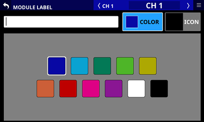
ICON button
Tap this button to open the icon selection area where icons for each module shown on channel screens can be set.(See “Setting module icons”.)
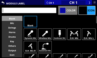
Keyboard area
Tap the keyboard buttons in this area to edit the user module label shown in the keyboard input area.
Tap the Copy button to copy the characters shown in the keyboard input area to the copy buffer.
Tap the Paste button to paste the characters in the copy buffer to the keyboard input area.
Setting and editing user module labels
User module labels can be set and edited.
NOTE
User module labels are not set by default.
1.To open the MODULE LABEL Screen, tap a user module label display area on the MODULE LABEL page of the LABEL SETUP Screen, or on a MODULE, SEND OVERVIEW, MIXER CONFIG or LIBRARY screen. (For a DCA module, tap the MODULE LABEL area on the Home Screen. For a MUTE GROUP, tap the Mute Group name area on the Mute Group Master page.)
2.Tap the keyboard buttons on the MODULE LABEL Screen to input the user module label.
User module labels can have up to 8 characters.
NOTE
The combination of characters input can be changed depending on the status of the Caps lock and Shift keyboard buttons on the MODULE LABEL Screen. See “Changing the keyboard keys” for details about changing the keyboard.
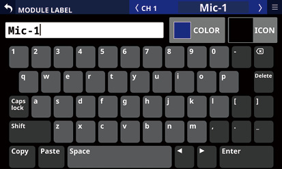
3.The input characters will be immediately used as the user module labels on various screens, including channel screens.
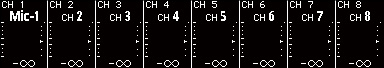
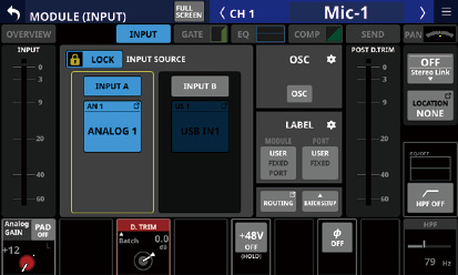
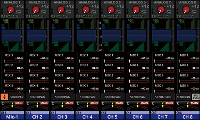
4.Tap the Enter button on the MODULE LABEL Screen to open the MODULE LABEL Screen for the next module to the right.
ATTENTION
The following symbols and punctuation marks cannot be input.
¥ / : * ? " < > |
NOTE
A USB keyboard connected to the top panel USB port can also be used to input and edit characters.
If a user module label cannot be shown completely in a display area, the end will be cut off. If the end is a number, up to two digits will be included in the abbreviated name.
The Caps lock and Shift button settings change the selection of characters that can be input as shown below.
NOTE
The Shift button automatically deactivates after inputting one character.
Setting for inputting numbers and lowercase letters
|
Caps lock button |
Off |
|
Shift button |
Off |
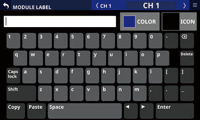
Setting for inputting numbers and uppercase letters
|
Caps lock button |
On (highlighted) |
|
Shift button |
Off |
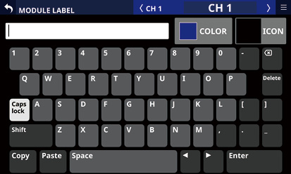
Setting for inputting symbols and lowercase letters
|
Caps lock button |
On (highlighted) |
|
Shift button |
On (highlighted) |
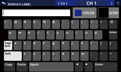
Setting for inputting symbols and uppercase letters
|
Caps lock button |
Off |
|
Shift button |
On (highlighted) |
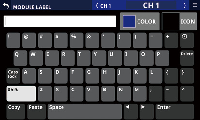
The set module label background colors shown on screens as well as the lit colors of channel color bars can be changed.
The factory default module color settings are as follows.
|
CH 1–40 |
Blue |
|
ST IN 1–2 |
Blue |
|
FX RTN 1–4 |
Green |
|
MIX when the BUS mode is AUX |
Orange |
|
MIX when the BUS mode is GROUP |
Purple |
|
MAIN L/R |
Red |
|
DCA |
Yellow |
|
Mute Group |
Red |
1.To open the MODULE LABEL Screen, tap a user module label display area on the MODULE LABEL page of the LABEL SETUP Screen, or on a MODULE, SEND OVERVIEW, MIXER CONFIG or LIBRARY screen. (For a DCA module, tap the MODULE LABEL area on the Home Screen. For a MUTE GROUP, tap the Mute Group name area on the Mute Group Master page of the DCA/Mute Group SETUP Screen.)
2.Tap the COLOR button on the MODULE LABEL Screen to open the color palette.
3.Tap a color in the color palette to change the module color setting.
This will change the module label background color shown on screens as well as the lit color of channel color bars.
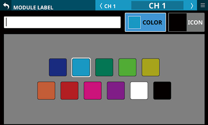
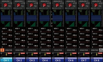
NOTE
Tapping the keyboard input area on a MODULE LABEL screen will reopen the keyboard.
Icons shown for modules on channel screens can be set.
NOTE
Module icons are not set by default.
1.To open the MODULE LABEL Screen, tap a user module label display area on a MODULE, SEND OVERVIEW, MIXER CONFIG or LIBRARY screen. (For a DCA module, tap the MODULE LABEL area on the Home Screen.)
2.Tap the ICON button on the MODULE LABEL Screen to open the icon selection area.
3.Tap an icon in the icon selection area to set it.
Set icons will be shown on MODULE LABEL and channel screens.
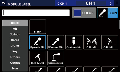
NOTE
To select icons not shown on the screen, swipe the icon selection area up and down to scroll the screen. The screen can also be scrolled by tapping the icon categories on the left side of the screen.
Tapping the keyboard input area on a MODULE LABEL screen will reopen the keyboard.
This unit has an AUTO MIXER Function designed for speech that uses a gain sharing technique to keep volume stable.
The AUTO MIXER of this unit compares each mic input and the sum of all mic inputs and automatically adjusts the AUTO MIXER GAIN level of each mic input so that the level of output from the AUTO MIXER is equivalent whether there is a single mic input or multiple mic inputs.
The balance of the channels can be altered. For example, the levels of specific channels can be mixed higher or lower according to their WEIGHT value settings. This will change the gain distribution, but the sum of output levels from the AUTO MIXER will not change.
The four AUTO MIXER groups (A/B/C/D) can each be used to create up to four independent mixes.
NOTE
The AUTO MIXER functions immediately after the FADER and MUTE of the CH 1–16 modules (i.e., post fader). For this reason, pre-send signals including those sent to monitors, are not affected.
Post send signals to MIX and FX buses are from after the AUTO MIXER.
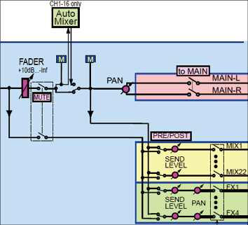
Extraction from the block diagram around the AUTO MIXER
The AUTO MIXER function of this unit is designed for meetings and other forms of speech. Be aware that it is not designed for instruments and music.
AUTO MIXER settings are subject to snapshots.
Preparations and procedures for using the AUTO MIXER function
1.Set the AUTO MIXER function to OFF before changing the following settings.
Adjust the mic preamp gains that will be subject to the AUTO MIXER and balance the mic volumes.
Set the faders to 0 dB and MUTE to OFF for the channels that will be subject to the AUTO MIXER.
2.Set the channel group to which mics subject to the AUTO MIXER are assigned to one of the AUTO MIXER groups (A, B, C or D). (See “ Channel group assignment button”.)
Set the channel group to which mics not subject to the AUTO MIXER are assigned to “---”.
3.Turn the AUTO MIXER function ON for the group selected in step 2. (See “ Group AUTO MIXER function ON/OFF buttons”.)
4.Turn the AUTO MIXER function itself ON. (See “ AUTO MIXER function overall ON/OFF button”.)
On this screen, make settings for the AUTO MIXER function included in the CH 1–16 modules.
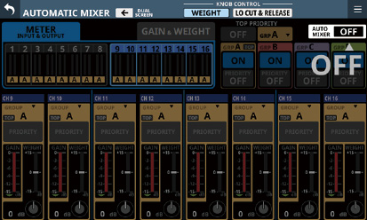
AUTOMATIC MIXER Screen display procedures
Use the following procedures to open this screen.
Tap Menu screen > Mixer Setup menu > Automatic Mixer
Tap the AUTO MIXER GROUP button when the AUTO MIXER parameter is shown in the SEND area on the Home Screen
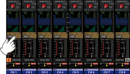
Tap the AUTO MIXER button on the MODULE (OVERVIEW) Screen of a CH 1–16 module
_AUTO-MIXER.jpg)
AUTOMATIC MIXER content explanation
.jpg)
AUTOMATIC MIXER Screen when LCD knobs are controlling WEIGHT
.jpg)
AUTOMATIC MIXER Screen when LCD knobs are controlling LO CUT & RELEASE
DUAL SCREEN button
Tap the ![]() or
or ![]() button to add display of the AUTOMATIC MIXER Screen to the touchscreen in the direction of the arrow. By doing this, all the AUTO MIXER settings and operation states for CH 1–16 (which are subject to the AUTO MIXER) can be checked and worked with at the same time on two touchscreens.
button to add display of the AUTOMATIC MIXER Screen to the touchscreen in the direction of the arrow. By doing this, all the AUTO MIXER settings and operation states for CH 1–16 (which are subject to the AUTO MIXER) can be checked and worked with at the same time on two touchscreens.
If the AUTOMATIC MIXER Screen is already open on the touchscreen in the direction of the arrow, tapping the ![]() or
or ![]() button will close the AUTOMATIC MIXER Screen on the tapped touchscreen.
button will close the AUTOMATIC MIXER Screen on the tapped touchscreen.
Knob target selection buttons
Tapping these buttons switches the operation targets of the LCD knobs shown at the bottom of the AUTOMATIC MIXER Screen. Those LCD knobs can be used to adjust the parameters shown.
The selected button will be highlighted.
|
Button |
Function |
|
WEIGHT (default) |
The WEIGHT value of each channel can be adjusted. |
|
LO CUT & RELEASE |
The LO CUT and RELEASE TIME of each group can be adjusted. |
NOTE
The knob operation target can also be changed by tapping the GAIN level meter () in the channel settings display area () or the WEIGHT setting indicator () area.
Use this button to activate priority of the groups selected for TOP PRIORITY.
Tap this button to turn the TOP PRIORITY setting ON or OFF. (Default: OFF)
ATTENTION
This button will be disabled if the Auto Mixer Priority Inhibit setting on the PREFERENCES screen is ON (default: ON). (See “ Auto Mixer Priority Inhibit switch”.)
When ON, the group selected for TOP PRIORITY will have increased priority and channels assigned to different groups will be muted. When on, this button and the following “TOP” icons will appear highlighted.
“TOP” icon for TOP PRIORITY subject (See “ TOP PRIORITY selection status”.)
“TOP” icons for group assignment buttons for channels that are assigned to this group (See “ Channel group assignment button”.)
.jpg)
.jpg)
AUTOMATIC MIXER Screen when LCD knobs are controlling WEIGHT
.jpg)
AUTOMATIC MIXER Screen when LCD knobs are controlling LO CUT & RELEASE
TOP PRIORITY group selection button
Use this to select the group to prioritize with the TOP PRIORITY ON/OFF button.
This shows the name of the group selected for TOP PRIORITY.
Tap this button to open the TOP PRIORITY group selection window.
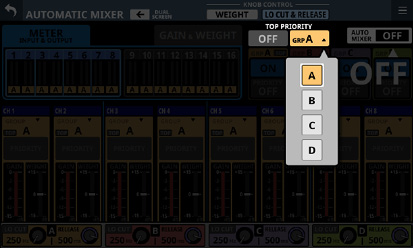
Tap an option to select the TOP PRIORITY group. (A is selected by default.)
AUTO MIXER function overall ON/OFF button
This turns on/off the AUTO MIXER function itself. (Default: OFF)
Tap this button to open a confirmation message.
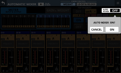
Tap the ON or OFF button to switch it on/off.
Tap the CANCEL button to close the confirmation message.
When ON, buttons will be highlighted.
When OFF, all AUTO MIXER parameters for all modules will appear dimmed.
![]() button
button
Tap this button to open the menu for the selected AUTOMATIC MIXER Screen.
Tap the menu ![]() or
or ![]() button to close the menu.
button to close the menu.
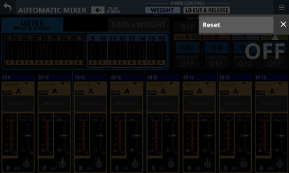
Tap the Reset button in the menu to open a confirmation message for resetting the AUTO MIXER settings to their factory defaults.
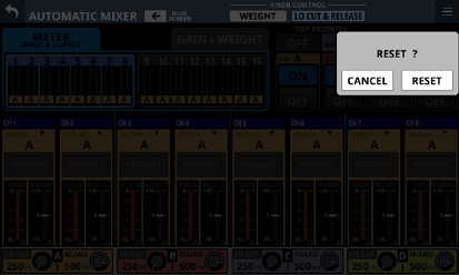
Tap the RESET button restore the AUTO MIXER function to its factory default settings.
Tap the CANCEL button to close the confirmation message.
.jpg)
AUTOMATIC MIXER Screen when LCD knobs are controlling WEIGHT
.jpg)
AUTOMATIC MIXER Screen when LCD knobs are controlling LO CUT & RELEASE
Meter and indicator display selection tabs
Use these tabs to select the display mode for the meter and indicator display area ().
Buttons selected by tapping will be highlighted.
|
Meter/indicator display mode |
Meaning |
|
METER INPUT & OUTPUT (default) |
Input and output level meters will be shown for the AUTO MIXER. The input levels from each channel to the AUTO MIXER are shown as yellow meters on the left side of each channel. The output levels of each channel from the AUTO MIXER are shown as yellowish-green meters on the right side of each channel. |
|
GAIN & WEIGHT |
AUTO MIXER GAIN level meters and WEIGHT setting indicators will be shown. GAIN level meters for the channels that are automatically controlled by the AUTO MIXER are shown in red on their left sides. WEIGHT setting indicators for each channel are shown to their right in light blue. |
Meter and indicator display area
This row of 16 channels of meters and indicators shows AUTO MIXER input and output levels and setting states.
The content shown can be switched by tapping the meter and indicator display selection tabs (). In addition, tapping this area switches the channels subject to operation in the channel settings display area ().
The selected display of channels subject to operation will become highlighted and the channel settings display area () will be shown. (default: CH1-8)
Group assignment states
This shows the group assignment state of each channel.
The background color depends on the selected group.
When the group AUTO MIXER function is OFF, these will appear dimmed.
If the selected group is TOP PRIORITY, a “TOP” icon will be shown to the right of the group name.
When the TOP PRIORITY setting is ON, the “TOP” icon will appear highlighted.
Group AUTO MIXER function ON/OFF buttons
These turn the AUTO MIXER function on/off for each group. (Default: ON)
Tap this button to open a confirmation message.
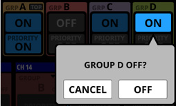
Tap the ON or OFF button to switch it on/off.
Tap the CANCEL button to close the confirmation message.
When ON, buttons will be highlighted.
When OFF, the AUTO MIXER parameters for the channels assigned to this group will appear dimmed.
.jpg)
AUTOMATIC MIXER Screen when LCD knobs are controlling WEIGHT
.jpg)
AUTOMATIC MIXER Screen when LCD knobs are controlling LO CUT & RELEASE
Group PRIORITY setting ON/OFF buttons
These turn on/off the PRIORITY settings of each group. (Default: OFF)
ATTENTION
This button will be disabled if the Auto Mixer Priority Inhibit setting on the PREFERENCES screen is ON (default: ON). (See “ Auto Mixer Priority Inhibit switch”.)
When ON, this button will appear highlighted and the priority of channels in the group that have their PRIORITY set to “ON” will be increased while those with PRIORITY set to “OFF” will be muted.
In addition, the channel PRIORITY setting ON/OFF buttons () that meet the following conditions will appear highlighted.
In the same group as the group PRIORITY setting ON/OFF buttons ()
Set to “ON”
.jpg)
.jpg)
AUTOMATIC MIXER Screen when LCD knobs are controlling WEIGHT
.jpg)
AUTOMATIC MIXER Screen when LCD knobs are controlling LO CUT & RELEASE
Channel settings display area
This shows the AUTO MIXER settings of each channel.
The background color depends on the selected group.
When the group AUTO MIXER function is OFF, this will appear dimmed.
.jpg)
AUTOMATIC MIXER Screen when LCD knobs are controlling WEIGHT
Channel group assignment button
Each channel can be assigned to 4 AUTO MIXER groups (A/B/C/D). Each group can be used to create up to four independent mixes.
This shows the name of the selected group.
The color of the channel setting display area changes according to the select group.
If the ![]() button is selected, it will not be subject to the AUTO MIXER and “---” will be shown.
button is selected, it will not be subject to the AUTO MIXER and “---” will be shown.
If the selected group is TOP PRIORITY, a “TOP” icon will be shown to the left of the group name. When the TOP PRIORITY setting is ON, this “TOP” icon will appear highlighted.
Tap this area to open a window where the channel group can be assigned.
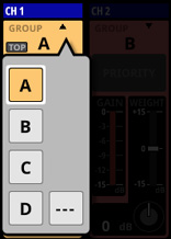
Tap an option to select the group for that channel. (Default: A)
Channel PRIORITY setting ON/OFF button
Use this to select a channel for prioritization when the Group PRIORITY setting ON/OFF button is ON.
Tap this button to turn PRIORITY ON or OFF for the channel. (Default: OFF)
When ON, the color of this button will become as follows.
|
Setting on the PRIORITY button of the group that the channel is assigned to |
Button color |
|
ON |
Appears highlighted |
|
OFF |
Appears dim light blue |
NOTE
This button will be disabled if the Auto Mixer Priority Inhibit setting on the PREFERENCES screen is ON (default: ON). (See “ Auto Mixer Priority Inhibit switch”.)
GAIN level meter
This shows the gain level as it is automatically adjusted by the AUTO MIXER function.
GATE indicator
This indicator shows whether or not the gate is open for the subject channel in the AUTO MIXER.
This lights when the GATE is closed and the input level to the AUTO MIXER is −90 dB or less. When the input level to the AUTO MIXER is −84 dB or higher and the GATE is open, it will be unlit.
WEIGHT setting indicator
Shows the WEIGHT value, which extends up or down from the center, as set by the WEIGHT knob ().
NOTE
The knob operation target can also be changed by tapping the GAIN level meter () or the WEIGHT setting indicator () area.
.jpg)
AUTOMATIC MIXER Screen when LCD knobs are controlling WEIGHT
.jpg)
AUTOMATIC MIXER Screen when LCD knobs are controlling LO CUT & RELEASE
Knob operation area
Use the corresponding LCD knobs to adjust the various AUTO MIXER parameters.
When LCD knobs control WEIGHT
The WEIGHT value of each channel can be set.
.jpg)
WEIGHT knob
This sets gain distribution within the same AUTO MIXER group for when multiple people are speaking at the same time.
WEIGHT value settings change the gain distribution, but the sum of output levels from the AUTO MIXER does not change.
When the knob target selection button (2) has been used to select “WEIGHT”, use the corresponding LCD knob (lit light blue) to adjust the WEIGHT value of that channel.
Range: −15 dB – +15 dB (default: 0 dB)
NOTE
This does not affect the volume when only one person is speaking.
Setting examples
Increase the WEIGHT value of the channel used by an important speaker.
Increase the WEIGHT value of channels that are difficult to hear.
Decrease the WEIGHT value of channels that sound louder than the others.
When LCD knobs are controlling LO CUT & RELEASE
The LO CUT and RELEASE TIME of each group can be set.
.jpg)
LO CUT
This low-cut filter for the group is applied to the signal that is used to determine the AUTO MIXER level. Use this for the purpose of reducing fluctuations in AUTO MIXER gain due to the impact of background noises that are unrelated to voices.
- 1 LO CUT on/off button
This button switches on/off the LO CUT for the group. (Default: off)
When the knob target selection button () has been used to select “LO CUT & RELEASE”, tap this button to switch the state.
When this is on, the button will appear highlighted.
- 2 LO CUT knob
This adjusts the cutoff frequency of the LO CUT for the group.
When the knob target selection button () has been used to select “LO CUT & RELEASE”, use LCD knobs 1/3/5/7 (lit orange/pink/purple/yellowish-green) to adjust the groups individually.
Range: 125 Hz – 4.00 kHz (default: 125 Hz)
RELEASE knob
Use this to adjust the time until the reduced gain level is restored to normal when only one person continues speaking after there had been multiple voices, for example.
When the knob target selection button () has been used to select “LO CUT & RELEASE”, use LCD knobs 2/4/6/8 (lit orange/pink/purple/yellowish-green) to adjust the release times for groups individually.
Range: 5 ms – 1.00 s (default: 500 ms)
 Group AUTO MIXER function OFF indicator
“OFF” will appear when the group AUTO MIXER function ON/OFF button is OFF.
Snapshots of unit mixer settings can be named and saved for recall at any time.
In addition to recalling them from the Snapshot List Screen, they can also be recall using USER KEYS, FOOTSWITCH and GPIO-IN controls.
The following data is included in snapshots.
NOTE
The INPUT SOURCE INPUT A / INPUT B setting is a function that has been added in Version 2.2.0. For this reason, the following will occur when recalling snapshots that were stored using an earlier version.
The input routing settings of the older version will be recalled as the input routing settings for INPUT A.
The INPUT B routing and the state of the INPUT A / INPUT B button switching will be retained from before recalling.
Input and output settings
Routing settings (INPUT/OUTPUT)
Internal oscillator input on/off
Analog gain
Pad on/off
Phantom power on/off
Phase button settings
Digital trim value settings
Direct out signal settings (on/off, trim, routing)
Insert input/output settings (on/off, point, routing)
Bus assignment settings (MIX bus, MAIN bus)
Analog gain, pad on/off and phantom power on/off for mounted SB-16D units
Signal processing settings
HPF parameters
EQ parameters
GEQ parameters
Dynamics parameters
Digital delay (delay time, on/off, point)
Effect parameters
Bus send settings (level, pre/post, pan/balance)
Pan/balance settings, image, mode
Fader/mute settings
Other module settings
DCA/MUTE group settings
Stereo link settings
Bus mode settings (AUX/GROUP)
Metering point settings
Module name, color and icon settings
User module label, module setting color and icon settings
LABEL SETUP Screen settings
MODULE (OUTPUT) Screen SELECT PORT LABEL mode setting
AFV settings
AUTO MIXER settings
Other settings
Internal oscillator settings (on/off, assignment, level, type, frequency)
Talkback settings (phantom power on/off, digital trim value)
Layer settings (layer key assignments, custom layer assignments, custom layer names for apps)
USER DEFINED CONTROLS settings
Brightness settings for the various displays
This setting data is saved.
Moreover, when recalling snapshots, specified parameters can be protected so that they are not changed. (For example, routings can be kept the same when recalling snapshots.)
NOTE
Settings of output connectors with the following signals assigned will not be changed by snapshot recalls.
SOLO DIRECT OUT L/R (See “ OUTPUT button”.)
TB to EXT 1/2 (See “ EXT 1 OUT / EXT 2 OUT buttons”.)
MONITOR 1 DIRECT OUT L/R (See “ Direct OUT PORT button (MONITOR 1)”.)
MONITOR 2 DIRECT OUT L/R (See “ Direct OUT PORT button (MONITOR 2)”.)
MONITOR 2 OUT L/R (See “ OUTPUT PORT button (MONITOR 2)”.)
For this reason, the following output routings might not be changed after snapshot recalls.
MIX 1–22
MAIN L/R
CH 1–40 Direct OUT
Insert Send
Example of MAIN L/R routing being affected
When the routing setting is
“MON 2 OUT L/R to ANALOG OUT 15/16”
and a snapshot is recalled with routing set to
“MAIN L/R OUT to ANALOG OUT 15/16”

The “MAIN L/R OUT to ANALOG OUT 15/16” setting
will not be recalled. Instead,
the “MON 2 OUT L/R to ANALOG OUT 15/16” setting
will be retained.
DCA spill mode will be deactivated if a snapshot is recalled while it is active.
Using snapshot functions at the top of the Menu Screen
Snapshot functions can be conducted using the snapshot function area on the Menu Screen and from the Snapshot List Screen.
In this explanation, areas where snapshot data are saved are called “slots” or “data slots”.
.jpg)
Snapshot number
This shows the number of the snapshot active for storing and recalling. This will blink if it is not the same as the current snapshot (most recently stored/recalled snapshot).
Tap this area to open the Snapshot List Screen. (See “Snapshot List Screen”.)
Snapshot name area
This shows the name of the snapshot active for storing and recalling. This will blink if it is not the same as the current snapshot (most recently stored/recalled snapshot).
Tap this area to open the Snapshot List Screen. (See “Snapshot List Screen”.)
Snapshot ![]() selection button
selection button
Tap this button to switch to the snapshot that is one number lower, also switching to the corresponding name.
Press and hold this button to continuously change the display to snapshots with lower numbers.
Tapping this when the snapshot number is “001” will show “P0xx”, which is the highest numbered preset.
Tapping this when the snapshot number is “P001” will switch to “128”.
Snapshot ![]() selection button
selection button
Tap this button to switch to the snapshot that is one number higher, also switching to the corresponding name.
Press and hold this button to continuously change the display to snapshots with higher numbers.
Tapping this when the snapshot number is “128” will switch to “P001”.
Tapping this when the snapshot number is “P0xx”, which is the highest numbered preset, will switch to “001”.
Tap this button to store (save) the current settings to the data slot shown. (See “Storing snapshots”.)
If a locked data slot is shown, this button will appear gray.
RECALL button
Tap this button to recall the data slot settings of the snapshot number/name shown. (See “Recalling snapshots”.)
If an empty data slot is shown, this button will appear gray.
![]() icon
icon
Tap this icon to open the CONFIRMATION settings window.
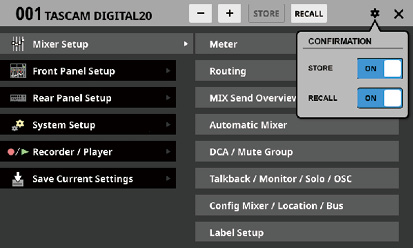
Tap these switches to set whether or not confirmation messages are shown when storing and recalling snapshots.
Tap this button again to close the CONFIRMATION setting window.
NOTE
These settings can also be set on the PREFERENCES Screen. (See “PREFERENCES screen”.)
![]() icon
icon
Tap this icon to close the Menu Screen.
![]() icon
icon
This icon will appear if the snapshot shown is locked.
![]() (EDIT) icon
(EDIT) icon
This icon will appear if settings have been changed for the last stored/recalled (current) snapshot.
Follow one of the procedures below to store (save) snapshot data.
Using STORE at the top of the Menu Screen
1.Tap the ![]() /
/![]() buttons to show the snapshot number ()/name () of the save destination data slot.
buttons to show the snapshot number ()/name () of the save destination data slot.
2.Tap the STORE button ().
If the save destination data slot is empty, the settings of the current snapshot will be stored in it.
If the save destination data slot is not empty and the CONFIRMATION settings window STORE setting is ON, a save confirmation message will be shown.
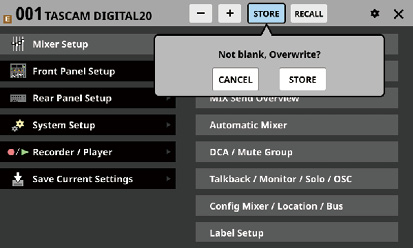
Tapping the STORE button on the confirmation message will store the current snapshot settings in the data slot and close the message.
Tapping the CANCEL button on the confirmation message will close the message without storing.
3.After storing completes, a storing completion message will appear for about two seconds.
Storing snapshots on the Snapshot List Screen
1.Do one of the following to show the save destination data slot in the snapshot list display area.
Tap the ![]() /
/![]() buttons
buttons
Turn LCD knob 8
Swipe the list up or down
Drag the scrollbar up or down
2.Tap the save destination data slot to select it.
This highlights the data slot.
3.Tap the STORE button ().
If the save destination data slot is empty, the settings of the current snapshot will be stored in it.
If the save destination data slot is not empty and the CONFIRMATION settings window STORE setting is ON, a save confirmation message will be shown.
Tapping the STORE button on the confirmation message will store the current snapshot settings in the data slot and close the message.
Tapping the CANCEL button on the confirmation message will close the message without storing.
4.After storing completes, a storing completion message will appear for about two seconds.
Storing using a control set on the USER DEFINED CONTROL Screen
If the Function and Parameter 1 settings on the USER DEFINED CONTROL Screen are as follows, the snapshot stored depends on the Parameter 2 setting.
|
Function |
Parameter1 |
|
Snapshot |
Store |
Pressing the control when Parameter 2 is set to “Selected”
This stores the current snapshot settings in the data slot shown by the snapshot number ()/name () at the top of the Menu Screen.
Pressing the control when Parameter 2 is set to “No.”
This stores the current snapshot settings in the data slot number specified by Parameter 3.
Pressing the control when Parameter 2 is set to “+Target Key”
Press simultaneously with a control that has Function set to Snapshot and Parameter 1 set to Target to store the current snapshot settings in the data slot number specified by Parameter 2 and Parameter 3 of that control.
However, even when Function is set to Snapshot and Parameter 1 is set to Target, this will not work if the key assigned to Parameter 2 as “Next” or “Prev” is pressed at the same time.
NOTE
Snapshot names when stored
When stored, snapshots are automatically named based on the current snapshot name with additional data added as follows to make the generation clear.
1st generation: base name
2nd generation: base name+_XX (2-digit number)
3rd generation: base name+_XX+a-z (single lowercase letter)
When a name cannot be added automatically,
|
Cannot generate default name automatically. Change name [CANCEL] [RENAME] |
will appear.
To change a name when storing, press the RENAME button to open the RENAME Screen.
Input a name that is not the same as existing data and tap Enter to store it.
*Conditions that prevent names from being added automatically
The current snapshot has a 1st generation name and data named “currentname_99” already exists.
The current snapshot has a 2nd generation name with “_XX” added and data named “currentname_XXz” already exists.
The current snapshot has a 3rd generation name.
When using a USER DEFINED CONTROL to store a snapshot excluding the current one, the name will be “USER KEY + data slot number”.
Follow one of the procedures below to recall (load) snapshot data.
Using RECALL at the top of the Menu Screen
1.Tap the ![]() /
/![]() buttons to open the snapshot number ()/name () of the data slot to be recalled.
buttons to open the snapshot number ()/name () of the data slot to be recalled.
2.Tap the RECALL button ().
If the CONFIRMATION settings window RECALL setting is ON, a confirmation message will be shown.
Tapping the RECALL button on the confirmation message will recall the snapshot and close the message.
Tapping the CANCEL button on the confirmation message will close the message without recalling.
3.After recalling completes, a recall completion message will appear for about two seconds.
Recalling snapshots on the Snapshot List Screen
1.Do one of the following to show the data slot to be recalled in the snapshot list display area.
Tap the ![]() /
/![]() buttons
buttons
Turn LCD knob 8
Swipe the list up or down
Drag the scrollbar up or down
2.Tap the data slot to be recalled to select it.
This highlights the data slot.
3.Tap the RECALL button ().
If the CONFIRMATION settings window RECALL setting is ON, a confirmation message will be shown.
Tapping the RECALL button on the confirmation message will recall the snapshot and close the message.
Tapping the CANCEL button on the confirmation message will close the message without recalling.
4.After recalling completes, a recall completion message will appear for about two seconds.
Recalling using a control set on the USER DEFINED CONTROL Screen
If the Function and Parameter 1 settings on the USER DEFINED CONTROL Screen are as follows, the snapshot recalled depends on the Parameter 2 setting.
|
Function |
Parameter1 |
|
Snapshot |
Recall |
Pressing the control when Parameter 2 is set to “Selected”
This recalls the settings in the data slot shown by the snapshot number ()/name () at the top of the Menu Screen.
Pressing the control when Parameter 2 is set to “Next” or “Prev”
This recalls the settings stored in the data slot one before/after (excluding presets) the snapshot shown by the number ()/name () at the top of the Menu Screen.
Pressing the control when Parameter 2 is set to “No.”
This recalls the settings in the data slot number specified by Parameter 3.
Pressing the control when Parameter 2 is set to “+Target Key”
Press simultaneously with a control that has Function set to Snapshot and Parameter 1 set to Target to recall the settings in the data slot number specified by Parameter 2 and Parameter 3 of that control.
NOTE
Limitations on recalling snapshot data from a different model (Sonicview 16XP/Sonicview 24XP)
When recalling snapshot data from a different model, a confirmation message like the following will be shown.
Message when recalling Sonicview 16XP snapshot data on a Sonicview 24XP
|
This is Sonicview 16 data. Some parameters cannot be recalled. Recall this data? [CANCEL] [RECALL] |
Tap the RECALL button to recall. When recalling, compatible settings will be recalled as is. The following incompatible settings will be handled as shown.
|
Snapshot settings that are not compatible between Sonicview 24XP and Sonicview 16XP models |
When recalling Sonicview 24XP data on a Sonicview 16XP |
When recalling Sonicview 16XP data on a Sonicview 24XP |
||||||||||||
|
1 |
Analog input 17–24 settings |
|||||||||||||
|
M/L 17–24 Input Assign |
Not imported |
No assignment |
||||||||||||
|
M/L 17–24 Phantom ON/OFF |
Not imported |
Set to OFF |
||||||||||||
|
M/L 17–24 PAD ON/OFF |
Not imported |
Set to OFF |
||||||||||||
|
M/L 17–24 Analog GAIN |
Not imported |
Set to minimum value |
||||||||||||
|
2 |
Fader 17–24 settings Fader 17–24 Custom Layer Mapping |
Not imported |
No assignment |
|||||||||||
|
3 |
Layer Key Assign |
Converted and imported as follows (re-creating original data as much as possible) |
Converted and imported as follows (re-creating original data as much as possible) |
|||||||||||
|
Sonicview 16XP Preset Layer |
Sonicview 24XP Preset Layer |
Recalled Sonicview 24XP data |
Sonicview 16XP settings after recall |
Recalled Sonicview 16XP data |
Sonicview 24XP settings after recall |
|||||||||
|
CH 1–16 |
CH 1–24 |
CH 1–24 |
|
CH 1–16 |
CH 1–16 |
|
CH 1–24 |
|||||||
|
CH 17–32 |
CH 25–40/ST IN/FX RTN |
CH 25–40/ST IN/FX RTN |
|
CH 17–32 |
CH 17–32 |
|
CH 1–24 |
|||||||
|
CH 33–40/ST IN/FX RTN |
MIX 1–22 |
MIX 1–22/MAIN L/R |
|
MIX 1–16 |
CH 33–40/ST IN/FX RTN |
|
CH 25–40/ST IN/FX RTN |
|||||||
|
MIX 1–16 |
DCA 1–8 |
|
DCA 1–8 |
MIX 1–16 |
|
MIX 1–22/MAIN L/R |
||||||||
|
MIX 17–22 |
CUSTOM 1 – CUSTOM 7 |
|
CUSTOM 1 – CUSTOM 7 |
MIX 17–22/MAIN L/R |
|
MIX 1–22/MAIN L/R |
||||||||
|
--- |
|
--- |
DCA 1–8 |
|
DCA 1–8 |
|||||||||
|
ATTENTION Be aware that the following will be discarded in this case.
|
CUSTOM 1 – CUSTOM 7 |
|
CUSTOM 1 – CUSTOM 7 |
|||||||||||
|
--- |
|
--- |
||||||||||||
Conduct snapshot function operations and setting data management and editing on this screen.
In this explanation, areas where snapshot and library data are saved are called “slots” or “data slots”.
Open this screen by tapping the snapshot number/name area at the top left of the Menu Screen.
.jpg)
Snapshot number
This shows the number of the snapshot active for storing and recalling.
This will blink if it is not the same as the current snapshot (most recently stored/recalled snapshot).
Snapshot name area
This shows the name of the snapshot active for storing and recalling.
This will blink if it is not the same as the current snapshot (most recently stored/recalled snapshot).
Snapshot ![]() selection button
selection button
This has the same function as the Snapshot ![]() selection button on the Menu Screen.
selection button on the Menu Screen.
Snapshot ![]() selection button
selection button
This has the same function as the Snapshot ![]() selection button on the Menu Screen.
selection button on the Menu Screen.
STORE button
This has the same function as the STORE button on the Menu Screen.
RECALL button
This has the same function as the RECALL button on the Menu Screen.
![]() icon
icon
This has the same function as the ![]() icon on the Menu Screen.
icon on the Menu Screen.
![]() icon
icon
Tap this icon to close the Snapshot List Screen and return to the Menu Screen.
![]() icon
icon
This has the same function as the ![]() icon on the Menu Screen.
icon on the Menu Screen.
![]() (EDIT) icon
(EDIT) icon
This has the same function as the ![]() icon on the Menu Screen.
icon on the Menu Screen.
LOCK/UNLOCK buttons
These show the locked/unlocked states of the data slots.
|
Button |
Use |
|
|
Unlocked |
|
|
Locked |
If setting data has not been saved in a slot, it will appear gray.
Tap a ![]() /
/![]() icon to open a LOCK/UNLOCK switching window for the data slot.
icon to open a LOCK/UNLOCK switching window for the data slot.
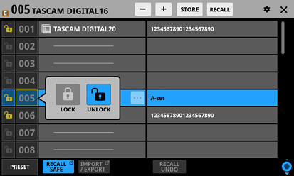
Tap a LOCK/UNLOCK option to switch the status.
Locked data slots cannot be deleted, renamed, overwritten and stored, or pasted into.
PRESET button
Tap this button to move to the preset data (P001–) location in the snapshot list.
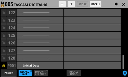
![]() icon
icon
This icon is shown for data slots that have had snapshots setting data copied to the internal storage.
NOTE
The ![]() icon is shown until new snapshot setting data is copied or until the unit power is turned off. The icon will also disappear if the copy source is deleted, overwritten or renamed.
icon is shown until new snapshot setting data is copied or until the unit power is turned off. The icon will also disappear if the copy source is deleted, overwritten or renamed.
RECALL SAFE button
This shows the Recall Safe setting status. If any are set to Recall Safe, this button will be highlighted.
Tap this button to open the SNAPSHOT RECALL SAFE Screen where settings that will be protected (retained) when snapshots are recalled can be selected. (See “SNAPSHOT RECALL SAFE screen”.)
IMPORT/EXPORT button
Tap this button to open the SNAPSHOT IMPORT/EXPORT Screen. (See “SNAPSHOT IMPORT / EXPORT screen”.)
Snapshot list
This shows snapshot numbers and names.
Data slots without any saved data are shown with horizontal bars.
The selected data slot will be highlighted.
“P” is added before the numbers of preset snapshots.
A yellow frame will be shown around the number of the current snapshot (most recently stored/recalled snapshot).
Snapshot editing menu button (![]() )
)
This button only appears for the selected data slot.
Tap this button to open a menu for editing the selected data slot.
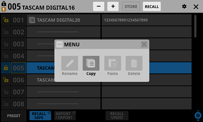
See “Library menu” for details.
RECALL UNDO/REDO button
Tap this button to undo/redo snapshot recall.
RECALL UNDO cancels the last snapshot recall and restores settings to their state before the recall.
RECALL REDO cancels the undo operation and restores settings to their state before the undo.
Comments
This shows the contents input in the COMMENT field on the RENAME Screen, which is opened by tapping the Rename button in the snapshot editing menu.
This shows as much of the added comments as possible from their beginnings.
Two lines will be shown if the content does not fit on one line. If the content still does not fit, the second line will end with …
Scroll knob and scrollbar
Drag the scrollbar to scroll the screen. The Snapshot List () and Comments () can also be scrolled by swiping up and down as well as by turning LCD knob 8.
Use this to edit library data.
.jpg)
These buttons will be gray when they cannot be used.
Rename button
Tap this button to open the RENAME Screen.
If the current data slot is locked or setting data has not been saved in it, this will appear gray.
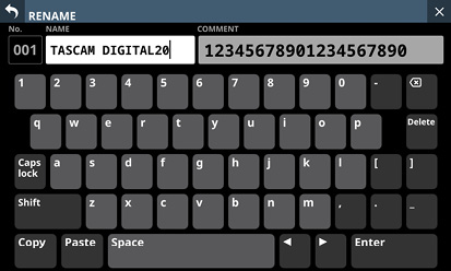
The snapshot name can have up to 16 characters.
The other library name can have up to 17 characters.
The snapshot comment can have up to 32 characters.
For snapshots, a comment field that can be edited will appear on the right side.
The combination of characters input can be changed depending on the status of the Caps lock and Shift keyboard buttons on the RENAME Screen. See “Changing the keyboard keys” for details about changing the keyboard.
ATTENTION
The following symbols and punctuation marks cannot be input.
¥ / : * ? " < > |
NOTE
A USB keyboard connected to the top panel USB port can also be used to input and edit characters.
Copy button
Tap this button to copy the settings data of the selected snapshot.
NOTE
The LIBRARY Screen for snapshots is the only one that has Copy and Paste functions.
Paste button
Tap this button to paste the settings data of the copied snapshot to the selected data slot.
This will appear gray for locked snapshots.
NOTE
The LIBRARY Screen for snapshots is the only one that has Copy and Paste functions.
Delete button
Tap this button to open a confirmation message for deleting the selected data.
If the current data slot is locked or setting data has not been saved in it, this will appear gray.
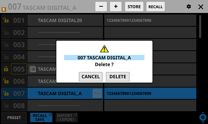
Tap the CANCEL button to close the confirmation message.
Tapping the DELETE button will delete the selected data and close the confirmation message.
![]() button
button
Tap this button to close the Library Menu.
1.Select the snapshot to copy and tap the snapshot editing menu button (![]() ).
).
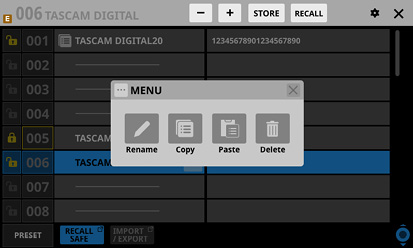
2.Tap the Copy button.
An ![]() icon will appear next to the copied snapshot.
icon will appear next to the copied snapshot.
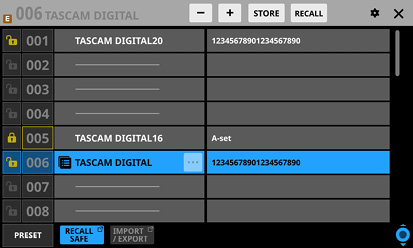
3.Select the data slot where it will be pasted and tap the snapshot editing menu button (![]() ).
).
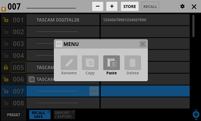
4.Tap the Paste button to paste it with a name given according to the snapshot storage rules. (See “ STORE button”.)
When a name cannot be added automatically, the RENAME screen will open. In this case, input a name that is not the same as existing data and tap the Enter button to paste and return to the Snapshot List Screen.
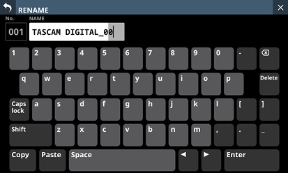
NOTE
When snapshot setting data is saved in the paste destination, a confirmation message will be shown.
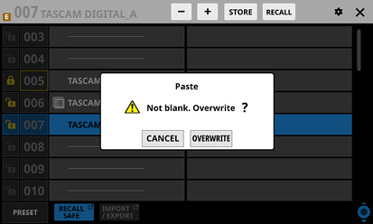
Tap the CANCEL button to close the confirmation message.
Tap the OVERWRITE button to paste it with a name given according to the snapshot storage rules. (See “ STORE button”.)
When a name cannot be added automatically, the RENAME screen will open. In this case, input a name that is not the same as existing data and tap the Enter button to paste and return to the Snapshot List Screen.
The ![]() icon is shown until new snapshot setting data is copied or until the unit power is turned off. The icon will also disappear if the copy source is deleted, overwritten or renamed.
icon is shown until new snapshot setting data is copied or until the unit power is turned off. The icon will also disappear if the copy source is deleted, overwritten or renamed.
The following settings can be made on this screen.
PARAMETER SAFE page
Use this to select parameters that will be protected (settings retained) when snapshots are recalled.
MODULE SAFE page
Use this to select modules that will be protected (settings retained) when snapshots are recalled.
Tap the RECALL SAFE button on the Snapshot List Screen to open this screen.
The recall safe function can be activated for specific groups of settings on this page.
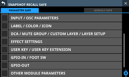
Tap checkboxes in rows to activate the recall safe function for them.
Selected rows will have check marks (![]() ) and be highlighted light blue.
) and be highlighted light blue.
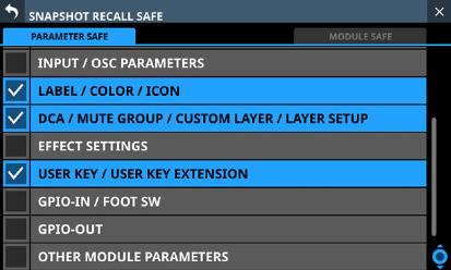
NOTE
Settings included in INPUT/OSC PARAMETERS
Analog Gain
Analog Gain GANG On/Off
PAD On/Off
Phantom On/Off
Phase
D.Trim
HPF Freq
HPF On/Off
CH OSC INPUT
OSC On/Off
OSC Assign
OSC Level
OSC Type
OSC Freq
Settings included in OTHER MODULE PARAMETERS
Gate/Expander/De-Esser Parameters
EQ Parameters
GEQ Parameters
Comp/Ducker Parameters
Module Delay Parameters
Fader
Mute
MAIN L/R Assign
PAN/BAL
PAN LINK
Image
Mode
Direct Out Parameters
AFV Parameters
Auto Mixer Parameters
Talkback Phantom On/Off
Talkback D.Trim
Metering Point
LCD Brightness
The recall safe function can be activated for modules on this page.
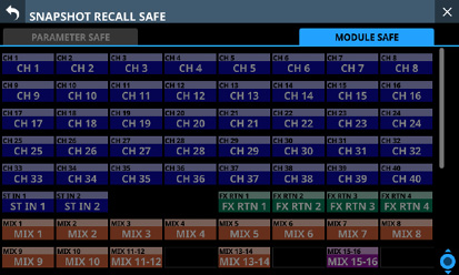
Tap the buttons for modules to be selected for recall safe protection.
Selected module buttons will be highlighted and have yellow frames.
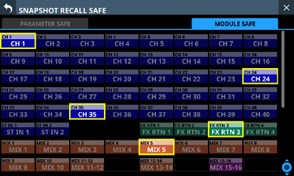
SNAPSHOT IMPORT / EXPORT screen
On the screen, snapshot settings data in this unit’s internal storage can be exported to loaded SD cards and USB flash drives. This data can also be imported from these external storage devices.
Tap the IMPORT/EXPORT button on the Snapshot List Screen to open this screen.
.jpg)
This shows the name of the currently selected media.
Tap this button to open a window where the import source/export destination can be set.
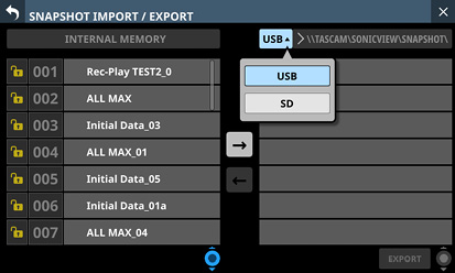
Options: USB, SD
Tap an option to switch the import source/export destination.
Folder
This shows the import source/export destination folder name.
The following folder on the external media is the import source/export destination folder.
\\TASCAM\SONICVIEW\SNAPSHOT
Snapshot list
This is a list of snapshots in the unit’s internal storage.
Snapshot List scroll knob and scrollbar
Drag the scrollbar to scroll the screen. The Snapshot List () can also be scrolled by swiping up and down as well as by turning LCD knob 4.
IMPORT/EXPORT mode buttons
Tap the ![]() (right arrow) button to switch the screen to export mode. The button will be highlighted (
(right arrow) button to switch the screen to export mode. The button will be highlighted (![]() ) when switched to export mode.
) when switched to export mode.
Tap the ![]() (left arrow) button to switch the screen to import mode. The button will be highlighted (
(left arrow) button to switch the screen to import mode. The button will be highlighted (![]() ) when switched to import mode.
) when switched to import mode.
NOTE
The unit will be set to export mode when it is turned on. After switching the setting, the last selected state will be retained until the unit is turned off.
List of data on selected media
This is a list of snapshot data on the selected media.
If the selected media type is not loaded, the following message will appear in the data list area.
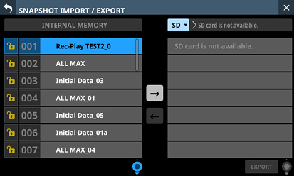
IMPORT/EXPORT button
The button shown depends on the setting of the IMPORT/EXPORT mode button ().
When in import mode, the button will be highlighted if both the import source and destination have been selected.
When in export mode, the button will be highlighted if the snapshot to be exported has been selected.
Tap this button when highlighted to execute the import/export operation.
Export data list scroll knob and scrollbar
If the number of snapshots on the selected media cannot all be shown on the screen at once, the scrollbar will appear and the scroll knob will be highlighted.
Drag the scrollbar to scroll the screen.
The list of data on the selected media () can also be scrolled by swiping up and down as well as by turning LCD knob 8.
1.Tap the snapshot name area () on the Menu Screen to open the Snapshot List Screen. (See “Snapshot List Screen”.)
2.Tap the IMPORT/EXPORT button on the Snapshot List Screen to open the SNAPSHOT IMPORT/EXPORT Screen. (See “SNAPSHOT IMPORT / EXPORT screen”.)
3.Connect the export destination media (SD card/USB flash drive).
4.Use the media selection button () to select the media to use as the export destination. (See “ Media selection button”.)
5.Tap the EXPORT/IMPORT mode ![]() () button to switch to export mode.
() button to switch to export mode.
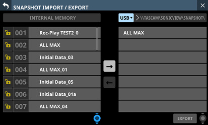
6.In the list of snapshots in the unit’s internal storage (), tap the snapshot data to be exported.
The snapshot data to be exported and the EXPORT button will be highlighted.
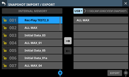
7.Tap the EXPORT button.
The exported snapshot data will be added to the exported data list (), and an export complete message will appear at the top of the screen.
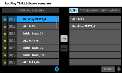
NOTE
A confirmation message will be shown if snapshot data with the same name already exists on the export destination media.
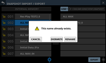
Tap the CANCEL button to cancel exporting and close the confirmation message.
Tap the OVERWRITE button to overwrite the data of the snapshot with the same name and close the confirmation message.
Tap the RENAME button to open the RENAME Screen. Input a name that is not the same as an existing snapshot name. Then, tap the Enter button to execute the export and return to the SNAPSHOT IMPORT/EXPORT Screen.
The following message will be shown if the export destination media is a locked SD card.
|
Cannot Export. SD card Locked. |
One of the following messages will be shown if the export destination media does not have enough open space.
|
Cannot Export. SD card is full. |
|
Cannot Export. USB flash drive is full. |
ATTENTION
If a snapshot created on a unit with firmware version 1.1.0 or later is recalled by a unit with firmware version 1.0.x, proper operation will not be possible, so the following restriction applies.
Snapshots created on units with firmware version 1.1.0 or later cannot be imported by units with firmware version 1.0.x. (Snapshots created by units with firmware version 1.0.x can be imported by units with firmware version 1.1.0 or later.)
1.Tap the snapshot name area () on the Menu Screen to open the Snapshot List Screen. (See “Snapshot List Screen”.)
2.Tap the IMPORT/EXPORT button on the Snapshot List Screen to open the SNAPSHOT IMPORT/EXPORT Screen. (See “SNAPSHOT IMPORT / EXPORT screen”.)
3.Connect the import source media (SD card/USB flash Drive).
4.Use the media selection button () to select the media to use as the import source. (See “ Media selection button”.)
5.Tap the EXPORT/IMPORT mode ![]() () button to switch to import mode.
() button to switch to import mode.
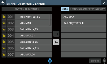
6.If the list of data on the selected media () has no snapshot data that you want to import, tap the folder selection button to the right of the media selection button to open the folder selection menu.
If the entire pull-down menu cannot be shown on the display, use LCD knob 8, the scrollbar or swipe gestures to scroll the screen.
Tap “ ” to the left of a folder name to open that folder and show its contents.
Tap “ ” to the left of the name of a folder to close it.
Tap the name of a folder to select it.
The name of the selected folder is reflected in the folder selection button path display field.
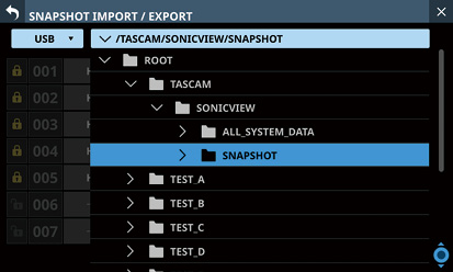
Folder selection pull-down menu example
7.After selecting the desired folder, tap the “” at the left end of the folder selection button to close the folder selection pull-down menu.
8.In the list of data on the selected media (), tap the snapshot data to be imported.
The snapshot data to be imported will be highlighted.
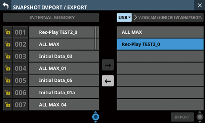
9.In the list of snapshots in the unit’s internal storage (), tap the input destination data slot.
The import destination data slot and the IMPORT button will appear highlighted.
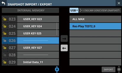
10.Tap the IMPORT button.
The imported snapshot data will be added to the snapshot list ().
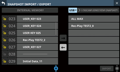
NOTE
An OVERWRITE confirmation message will be shown if snapshot data with the same name as the import source already exists in the import destination data slot.
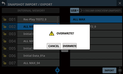
A REPLACE confirmation message will be shown if snapshot data with a different name from the import source exists in the import destination data slot.
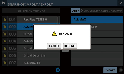
Tap the CANCEL button to cancel importing and close the confirmation message.
Tap the OVERWRITE button to import and overwrite the data of the snapshot with the same name and close the confirmation message.
Tap the REPLACE button to import and overwrite snapshot data with a different name and close the confirmation message.
The following message will be shown if the import destination slot is locked.
|
Cannot Import. Target Locked. |
This unit can store (save) and recall groups of various settings in libraries.
The selected GATE/EXPANDER/DE-ESSER type and its parameter settings
EQ parameter settings
The selected COMP/DUCKER type and its parameter settings
The selected FX type and its parameter settings
GEQ parameter settings
CH 1–40 and ST IN 1–2 module parameter settings
FX RTN 1–4 module parameter settings
MIX 1–22 and MAIN L/R Master module parameter settings
Tap the LIBRARY button on the GATE/EXP/DE-ESSER, EQ, COMP/DUCKER, FX or GEQ module screen to open the corresponding LIBRARY Screen.
_CH1.jpg)
CH 1–40 MODULE (EQ) Screen
To open LIBRARY screens (LIBRARY MODULE INPUT, LIBRARY MODULE FX RTN and LIBRARY MODULE OUTPUT screens) for modules, tap the ![]() button at the top right of a MODULE Screen. Then, tap MODULE Library in the menu list that appears.
button at the top right of a MODULE Screen. Then, tap MODULE Library in the menu list that appears.
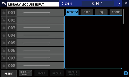
The parameters included in module libraries are the same as the parameters used for Copy MODULE. (See “MODULE menu”.)
Use various library functions and manage and edit library data on these screens.
_No(2020).jpg)
Library list
This shows library item numbers and names.
Data slots without any saved data are shown with horizontal bars.
The selected data slot will be highlighted.
“P” is added before the numbers of library presets.
LIBRARY menu button (![]() )
)
This button only appears for the selected data slot.
Tap this button to open the library menu for editing the selected data slot.
_CH1_pop_Library-Menu.jpg)
See “Library menu” for details.
Preview display
This shows a preview of the selected library data.
For module libraries, tap the tabs to change the preview contents.
Corresponding module name
This shows the user module label of the module active for library storing and recalling.
LOCK/UNLOCK buttons
These show the locked/unlocked states of the data slots.
|
Button |
Use |
|
|
Unlocked |
|
|
Locked |
If setting data has not been saved in a slot, it will appear gray.
Tap a ![]() /
/![]() icon to open a LOCK/UNLOCK switching window for the data slot.
icon to open a LOCK/UNLOCK switching window for the data slot.
_CH1_pop_Lock-Menu.jpg)
Tap a LOCK/UNLOCK option to switch the status.
Locked data slots cannot be deleted, renamed, or overwritten and stored.
PRESET button
Tap this button to move to the preset data (P001–) location in the library list.
_CH1_PRESET.jpg)
RECALL SAFE button
This is shown for module libraries.
This shows the Recall Safe setting status. If any are set to Recall Safe, this button will be highlighted.
Tap this button to open the MODULE RECALL SAFE Screen where settings that will be protected (retained) when module libraries are recalled can be selected. (See “MODULE RECALL SAFE screens”.)
STORE button
Tap this button after selecting a data slot to store the currently selected module settings to that data slot.
If no data slot is selected or locked library data is selected, this button will appear gray.
Library data names when stored are as follows.
EQ/GEQ Library
USER MODULE LABEL_MMDDhhmm (month, day, hour, minute)
Example: CH1_06091557, Vocal_06091558
Dynamics Library
|
When the USER MODULE LABEL is already set |
USER MODULE LABEL_MMDDhhmm (for example, Vocal_06091558) |
|
When the USER MODULE LABEL is not set |
Dynamics type_month day hour minute (without spaces) (for example, “GATE_06091557”) |
FX Library
FX TYPE name_month day hour minute (without spaces)
Example: REVERB_06091557, ST REV_06091558
Module Library
Module name_month day hour minute
Example: CH1_06091557, Vocal_06091558
NOTE
If the data name when storing is the same as an existing data name, the following message will be shown.
|
Default name already exists. change name. [CANCEL] [RENAME] |
A confirmation message will be shown if the selected data slot has settings data.
_CH1_STORE_pop_Replace.jpg)
Tap the Cancel button to cancel storing in the library and close the confirmation message.
Tap the Replace button to overwrite the selected data slot with the current settings and close the confirmation message.
RECALL button
On LIBRARY MODULE Screens, after selecting the data slot, tap this button to open a window to confirm the data to be recalled.
_CH1_RECALL_pop_Recall.jpg)
Tap the button for the desired recall data to open a recall confirmation window.
_CH1_RECALL_pop_Recall.jpg)
Tap the Cancel button in the recall confirmation window to cancel recalling from the library and close the confirmation message.
Tap the Recall button in the recall confirmation window to recall the library settings data for the selected recall items to the currently selected module and return to the MODULE Screen.
On GATE/EXP/DE-ESSER, EQ, COMP/DUCKER, FX and GEQ library screens, after selecting the data slot, tap this button to open a recall confirmation window.
_CH1_RECALL_pop_Recall.jpg)
Tap the Cancel button to cancel recalling from the library and close the confirmation message.
Tap the Recall button to recall the library settings data to the currently selected module and return to the MODULE Screen.
If no data slot is selected or a data slot that does not have saved data is selected, this button will appear gray.
RECALL UNDO/REDO button
Tap this button to undo the last executed recall operation for that library or to redo that operation.
Undo and redo are only possible with the module that was last used for recall with that library. If a different module is selected or recall has not been conducted since startup, the Undo button will appear gray.
Scroll knob and scrollbar
Drag the scrollbar to scroll the screen. The LIBRARY List can also be scrolled by swiping up and down as well as by turning LCD knob 8.
Use the following MODULE RECALL SAFE screens to select parameters that will be protected (settings retained) when module libraries are recalled.
MODULE INPUT RECALL SAFE screen
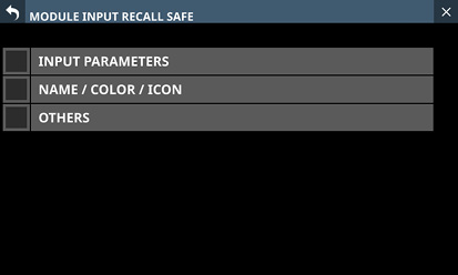
MODULE FX RTN RECALL SAFE screen
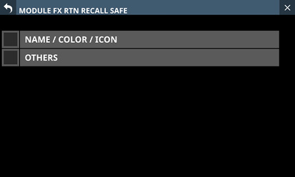
MODULE OUTPUT RECALL SAFE screen
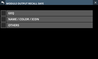
Tap the RECALL SAFE buttons on the corresponding module library screens to open these screens.
NOTE
Settings included in INPUT PARAMETERS on the MODULE INPUT RECALL SAFE Screen
Analog Gain
Analog Gain GANG On/Off
Phantom On/Off
PAD On/Off
Phase
D.Trim
HPF Freq
HPF On/Off
The following parameters are not included in module libraries.
Routing
USER DEFINED CONTROLS LIBRARY Screen
This unit can store (save) and recall USER DEFINED CONTROLS Screen settings in libraries.
Tap the LIBRARY button to open the USER DEFINED CONTROLS LIBRARY Screen.
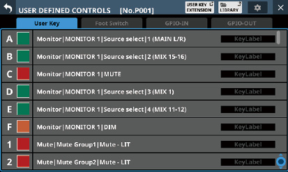
USER DEFINED CONTROLS LIBRARY Screen structure
Use various library functions and manage and edit library data on these screens.
.jpg)
Library list
This shows library item numbers and names.
Data slots without any saved data are shown with horizontal bars.
The selected data slot will be highlighted.
“P” is added before the numbers of library presets.
A yellow frame will be shown around the number of the current library (most recently stored/recalled library).
LIBRARY menu button (![]() )
)
This button only appears for the selected data slot.
Tap this button to open the library menu for editing the selected data slot.
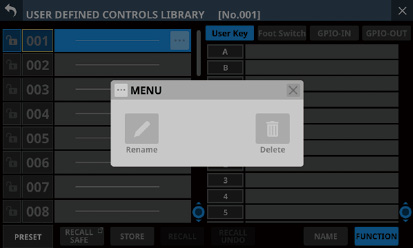
See “Library menu” for details.
Scroll knob and scrollbar
Drag the scrollbar to scroll the Library List. The Library List can also be scrolled by swiping up and down as well as by turning LCD knob 4.
Current library number
This shows the number of the current library (most recently stored/recalled library).
Preview display
This shows a preview of the selected library data. Tap the tabs to change the preview contents.
Swipe the preview area up and down to scroll the Library List. This can also be scrolled by turning LCD knob 8.
LOCK/UNLOCK buttons
These show the locked/unlocked states of the data slots.
|
Button |
Use |
|
|
Unlocked |
|
|
Locked |
If setting data has not been saved in a slot, it will appear gray.
Tap a ![]() /
/![]() icon to open a LOCK/UNLOCK switching window for the data slot.
icon to open a LOCK/UNLOCK switching window for the data slot.
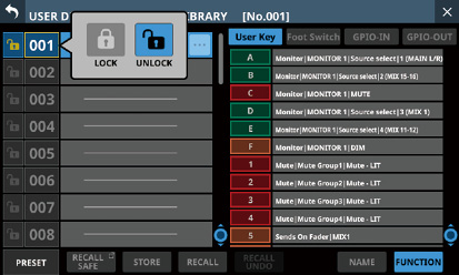
Tap a LOCK/UNLOCK option to switch the status.
Locked data slots cannot be deleted, renamed, or overwritten and stored.
PRESET button
Tap these buttons to move to the preset data location in the library list.
RECALL SAFE button
This shows the Recall Safe setting status. If any are set to Recall Safe, this button will be highlighted.
Tap this button to open the following RECALL SAFE Screen where settings that will be protected (retained) when libraries are recalled can be selected.
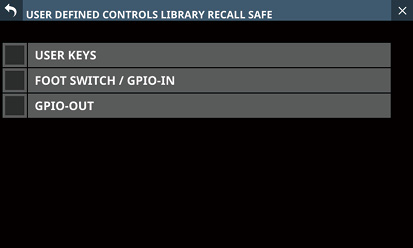
STORE button
Tap this button after selecting a data slot to store the current settings to that data slot.
If no data slot is selected or locked library data is selected, this button will appear gray.
Library data names when stored are as follows.
UDC_month day hour minute (without spaces)
If the data name when storing is the same as an existing data name, the following message will be shown.
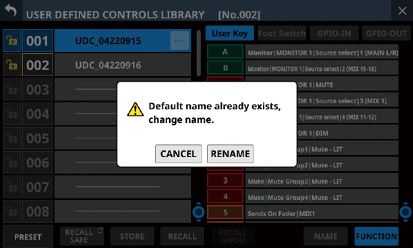
A confirmation message will be shown if the selected data slot has settings data.
![]()
Tap the Cancel button to cancel storing in the library and close the confirmation message.
Tap the Replace button to overwrite the selected data slot with the current settings and close the confirmation message.
RECALL button
Select the data desired for recall and tap the RECALL button to open a recall confirmation window.
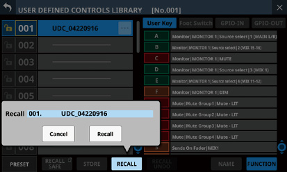
Tap the Cancel button to cancel recalling from the library and close the confirmation message.
Tap the Recall button to recall the selected data.
RECALL UNDO/REDO button
Tap this button to undo the last executed recall operation for that library or to redo that operation.
Preview display switches
These switch the display of user keys in preview display area.
|
Button |
Meaning |
|
NAME |
Key labels are shown. (See “ |
|
FUNCTION |
User key function names are shown. |
On this screen, settings for the entire mixer including all snapshot and library data (“All System Data”) can be handled in the following ways.
All System Data can be saved as a file to the internal storage
All System Data can be recalled from the internal storage (and applied to the mixer)
All System Data can be backed up (exported as a file) to an SD card or USB flash drive
All System Data can be restored (imported as a file) from an SD card or USB flash drive to the internal storage
NOTE
The Password setting on the Network Setup Screen is excluded when backing up and restoring All System Data.
Tap Menu Screen > System Setup menu > All System Data to open this screen.
.jpg)
List of saved files
This list shows All System Data Files that have been saved in the internal storage.
The date and time when the All System Data file was saved is shown to the right of the file name.
The selected file is highlighted.
![]() buttons
buttons
Tap one of these buttons to open a menu window that enables the following operations on the selected All System Data file.
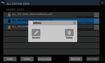
|
Menu item |
Explanation |
|
Rename |
This opens the Rename Screen where the name of the selected All System Data file can be changed. |
|
Delete |
This opens a confirmation message for deleting the selected All System Data file.
|
SAVE button
Tap this button to save All System Data to the internal storage. (See “Saving all mixer settings”.)
LOAD button
Tap this button to load All System Data from the internal storage. (See “Loading all mixer settings”.)
If no All System Data file is selected, this button will appear gray.
NOTE
If the following two conditions apply, loading will not be possible and the button will appear gray.
OA Tally Inhibit switch is ON (See “ OA Tally Inhibit switch”.)
ON AIR Tally is input to GPIO-IN
Factory Reset button
This button restores setting values to their factory defaults by clearing all unit settings to their default values and erasing all types of user data* saved in the internal memory. (See “Restoring factory default settings”.)
*User data saved in internal memory includes
Saved All System Data
Data stored in snapshots
Data stored in various LIBRARY Screens
NOTE
If the following two conditions apply, resetting will not be possible and the button will appear gray.
OA Tally Inhibit switch is ON (See “ OA Tally Inhibit switch”.)
ON AIR Tally is input to GPIO-IN
BACKUP button
If no All System Data file is selected, this button will appear gray.
Tap this button when an All System Data file is selected to open a confirmation message for backing up that data to external memory. (See “Backing up all mixer settings”.)
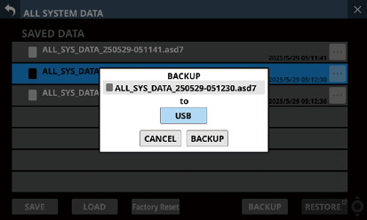
RESTORE button
Tap this button to open the ALL SYSTEM DATA RESTORE Screen. (See “Restoring all mixer settings”.)
Scroll knob and scrollbar
If all the saved files cannot all be shown on the screen at once, the scrollbar will appear and the scroll knob will be highlighted.
Drag the scrollbar to scroll the screen. The list of saved files () can also be scrolled by swiping up and down as well as by turning LCD knob 8.
Follow the procedures below to save all mixer settings (All System Data) to the internal storage.
1.Tap the SAVE () button to open a confirmation message for saving All System Data.
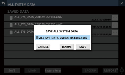
2.Tapping the SAVE button on the confirmation message will save All System Data to the internal storage and close the confirmation message.
The name shown on the confirmation message will be added to the list of saved files ().
Follow the procedures below to load all mixer settings (All System Data) from the internal storage (applying them to the mixer).
1.Tap the LOAD button () when an All System Data file is selected to open a confirmation message to load that data.
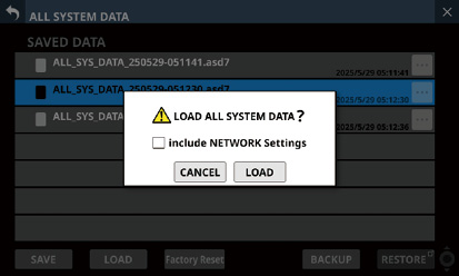
NOTE
To load network settings, tap the “include NETWORK Settings” check box on the confirmation message to add a check (![]() ) to it.
) to it.
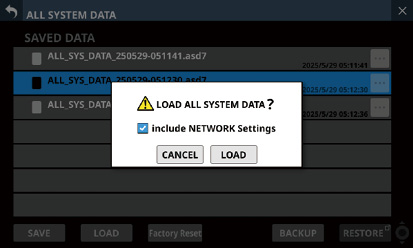
2.Tapping the CANCEL button on the confirmation message will close the message.
Tapping the LOAD button on the confirmation message will start loading the selected All System Data from the internal storage and close the confirmation message. The message shown below will appear while loading. After loading completes, the file will no longer be selected.
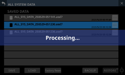
ATTENTION
Use caution, because loading All System Data will replace all Snapshot and LIBRARY settings data with the loaded data.
To keep the current data, save it before loading.
All System Data cannot be loaded with an IF-MTR32 that is currently recording or playing. Stop IF-MTR32 recording/playback before loading.
DCA spill mode will be deactivated if a snapshot is recalled while it is active.
All mixer settings (All System Data) in the internal storage can be backed up (exported as a file) to an SD card or USB flash drive.
1.Connect the media to use for backup.
2.Tap the file to be backed up to select it.
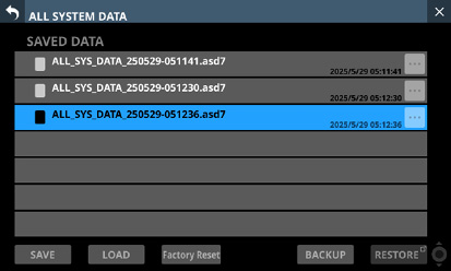
3.Tap the BACKUP button.
A confirmation message will appear.
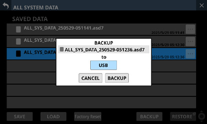
If both an SD card and a USB flash drive are connected, tap the media selection button shown with a and select the media to use for the backup.
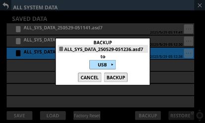
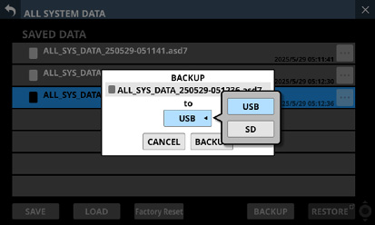
4.Tapping the BACKUP button on the confirmation message will back up the All System Data file.
The backup data will be saved in the following fixed folder on the media used for backup.
\\TASCAM\SONICVIEW\ALL_SYSTEM_DATA
If that folder does not exist on the backup media, it will be created.
A confirmation message will be shown if a file with the same name already exists on the backup media.
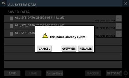
Tap the CANCEL button to close the confirmation message.
Tap the OVERWRITE button to overwrite the All System Data file with the same name and close the confirmation message.
Tap the RENAME button to open the RENAME Screen. Input a name that is not the same as an existing All System Data file name. Then, tap the Enter button to execute the backup and return to the ALL SYSTEM DATA Screen.
The following message will be shown if the backup destination media is a locked SD card.
|
Cannot Backup. SD card Locked. |
One of the following messages will be shown if the backup destination media does not have enough open space.
|
Cannot Backup. SD card is full. |
|
Cannot Backup. USB flash drive is full. |
Tap the CANCEL button to close the confirmation message.
Tapping the BACKUP button will back up (export) the All System Data file from the internal storage to the selected external media and close the confirmation message.
All mixer settings (All System Data) that is backed up on an SD card or USB flash drive can be imported to the internal storage.
ATTENTION
If a Snapshot created on a unit with firmware version 1.1.0 or later is recalled by a unit with firmware version 1.0.x, proper operation will not be possible, so the following restriction applies.
All System Data created on units with firmware version 1.1.0 or later cannot be restored on units with firmware version 1.0.x. (All System Data created by units with firmware version 1.0.x can be restored on units with firmware version 1.1.0 or later.)
NOTE
Restoring imports the All System Data on an external storage device as a file to the internal storage.
This does not affect the mixer settings.
To apply imported All System Data settings to the mixer settings, load the All System Data file. (See “Loading all mixer settings”.)
1.Connect the media that has the All System Data file to be restored written to it.
2.Tap the RESTORE button.
The ALL SYSTEM DATA RESTORE Screen will open.
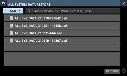
NOTE
If no SD or USB flash drive is connected, the following pop-up message will appear.
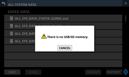
3.Tap the media selection button to select the media that has the All System Data file to be restored.
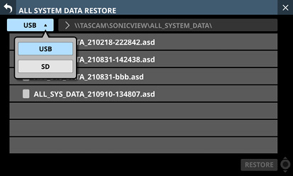
NOTE
If either an SD card or a USB flash drive is connected, but not both, the media selection menu will not be shown.
4.If the file you want to restore is not in the shown folder, tap the folder selection button to the right of the media selection button to open the folder selection pull-down menu.
If the entire pull-down menu cannot be shown on the display, use LCD knob 8, the scrollbar or swipe gestures to scroll the screen.
Tap “” to the left of a folder name to open that folder and show its contents.
Tap “” to the left of the name of a folder to close it.
Tap the name of a folder to select it.
The name of the selected folder is reflected in the folder selection button path display field.
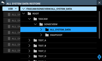
Folder selection pull-down menu example
5.After selecting the desired folder, tap the “” at the left the end of the folder selection button to close the folder selection pull-down menu.
6.Select the file to restore, and tap the RESTORE button.
A confirmation message will appear.
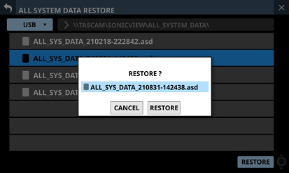
7.Tapping the RESTORE button on the confirmation message will restore the file.
A confirmation message will be shown if a file with the same name already exists on the restore destination (internal storage).
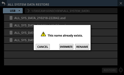
Tap the CANCEL button to close the confirmation message.
Tap the OVERWRITE button to overwrite the All System Data file with the same name and close the confirmation message.
Tap the RENAME button to open the RENAME Screen. Input a name that is not the same as an existing All System Data name. Then, tap the Enter button to restore the data and return to the ALL SYSTEM DATA Screen.
One of the following messages will be shown if the internal storage does not have enough open space.
|
Cannot Restore. Internal memory is full. |
Restoring factory default settings
Unit settings can be restored to their factory default state by clearing all unit settings to their defaults and deleting all types of user data* saved in the internal memory.
*User data saved in internal memory includes
Saved All System Data
Data stored in snapshots
Data stored in various LIBRARY Screens
1.Tap the Factory Reset () button to open a message confirming factory reset execution.
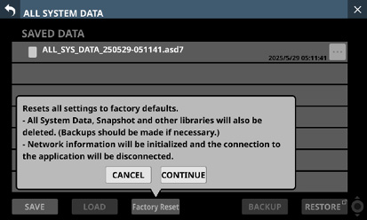
2.Tapping the CANCEL button on the confirmation message will close the message.
Tap the CONTINUE button in the confirmation message to open a reconfirmation message.
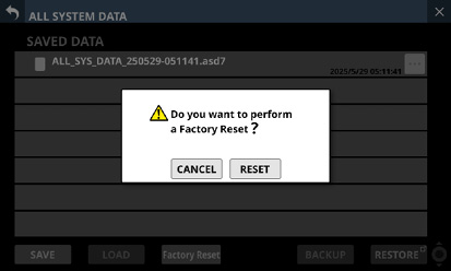
3.Tapping the CANCEL button in the reconfirmation message will close the message.
Tapping the RESET button in the reconfirmation message will execute the factory reset.
The following message will appear on every touchscreen while the factory reset is being executed.
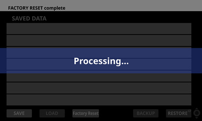
Normal display will be restored after the factory reset completes.
NOTE
Executing a factory reset will delete all types of user data saved in the internal memory. Back up various data to external storage as necessary.
Network settings will also be reset, so the unit will be disconnected from the network.
This screen shows information about the entire system and errors.
Tap Menu Screen > System Setup > Information to open this screen.
When this screen is opened, the last open page will be shown again if the unit is functioning properly.
The ERROR page will open if an error or alert is occurring with the unit.
.jpg)
SYSTEM CLOCK
This show the system clock status along with the sampling frequency and master clock currently used for operation.
Tap this area to open the SYNC CLOCK Screen. (See “SYNC CLOCK screen”.)
SLOT
This shows the names of the expansion cards installed in SLOT 1 and SLOT 2.
Tap this area to open the SLOT SETUP Screen. (See “SLOT SETUP screen”.)
These fields will be empty when nothing is installed.
MEDIA
This shows the USB flash drive and SD card states.
Tap this area to open the Media Manage Screen. (See “Media Manage Screen”.)
RECORDER/PLAYER
This shows the operation status of the internal recorder/player.
Tap this area to open the RECORDER/PLAYER Screen. (See “RECORDER/PLAYER Screen”.)
AVAILABLE MEMORY
This shows the amount of available memory that can be used by the system.
“Checking memory…” will be shown immediately after startup. After a while, the available memory will be shown.
If this unit is operated continuously without turning the power off for a long time, the available memory could decrease.
If the available memory decreases to the red bar, the following error message will be shown at the top of the screen. A message window with the same content will also be shown.
|
Insufficient memory. A system reboot is recommended to ensure stable operation. - The reboot should take less than a minute. - During system reboot audio and operation will be interrupted. |
In this case, in order to maintain stable operation of the system, as soon as is convenient, use the POWER switch on the back of the unit to restart it.
TEMPERATURE
These show the temperature states of the system, CPU and DSP.
Tap this area to open the PREFERENCES Screen. (See “PREFERENCES screen”.)
COOLING FAN
This shows the operation status of the internal cooling fan.
Tap this area to open the PREFERENCES Screen. (See “PREFERENCES screen”.)
MTR
This shows the operational status of the IF-MTR32 (multitrack recorder) card installed in SLOT 1 or SLOT 2 on the rear panel.
Tap this area when an IF-MTR32 (multitrack recorder) card is installed to open the MULTI TRACK RECORDER Screen. (See “MULTI TRACK RECORDER Screen”.)
OPEN SOURCE SOFTWARE LICENSE
This shows open source software licenses.
Tap this area to open the OPEN SOURCE SOFTWARE LICENSE Screen. (See “OPEN SOURCE SOFTWARE LICENSE Screen”.)
When errors and alerts occur (“Sonicview 16XP/24XP Error Screen SYSTEM error/alert message list”), they are listed on this page.
The content of this page is cleared when the unit is turned off.
.jpg)
Error/alert information area
When an error or alert occurs, a message will be shown at top of every touchscreen. (See “Error/alert message display”.)
Error/alert list
When errors/alerts occur, details about them are shown.
Date and time: YYYY/MM/DD HH:MM
New errors/alerts are shown in the order that they occur from the top.
Background colors differ according to the error status.
|
Error status |
Background color |
|
Error currently occurring |
Red |
|
Alert currently occurring |
Yellow |
|
Resolved error |
Gray |
When an error is resolved its background color becomes gray. This includes device temperature errors and other errors that are resolved automatically as well as system clock errors and other errors that are resolved manually.
![]() buttons
buttons
Tap these buttons to open setting screens related to each error/alert.
![]() buttons
buttons
Tap ![]() buttons on error/alert to clear them from the list.
buttons on error/alert to clear them from the list.
NOTE
This button does not appear for errors that are currently occurring, which cannot be cleared from the list.
Scroll knob and scrollbar
These appear when all errors/alerts cannot be shown on the display at the same time.
Drag the scrollbar to scroll the screen. Errors can also be scrolled by swiping up and down as well as by turning LCD knob 8.
ALL CLEAR button
Tap this button to open a confirmation message for clearing all error and alert history.
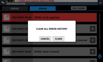
Tapping the CLEAR button will clear all error and alert history.
NOTE
Errors that are currently occurring will not be cleared from the error list.
When an error or alert occurs, a message will be shown at top of every touchscreen (“Sonicview 16XP/24XP Error Screen SYSTEM error/alert message list”).
.jpg)
Error/alert messages open on the Home Screen
.jpg)
Error/alert messages closed on the Home Screen
Number of errors/alerts
This shows the number of errors and alerts that are currently occurring.
Error/alert message switching buttons
These are shown when multiple errors/alerts are occurring.
Tap these buttons to change the content shown in the error/alert message display area () to a different message.
Error/alert message display area
This shows the content of an error/alert that is currently occurring. The number at the beginning of the message shows the order that it occurred.
Tap this area to open the screen that corresponds to the content of the error/alert.
Blinking error bar
Until errors and alerts are resolved, a blinking red line will be shown at top of every touchscreen.
Close button
If the error/alert message display area () hides part of the display and makes operation impossible, this button can be tapped to close it.
NOTE
If a new error/alert occurs when the error/alert message display area () is closed, it will reopen automatically.
Open button
Tap this button to reopen the error/alert message display area () if it has been closed.
When an alert occurs, a message window like the following will appear on the right touchscreen (“Sonicview 16XP/24XP Error Screen SYSTEM error/alert message list”).
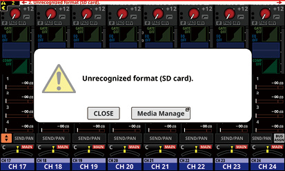
Tap the CLOSE button to close the message.
Tap the screen name button to open the screen that corresponds to the content of the alert on the right touchscreen.
OPEN SOURCE SOFTWARE LICENSE Screen
This screen shows information about licenses for open source software used by this unit.
Tap OPEN SOURCE SOFTWARE LICENSE on the INFORMATION Screen to open this screen.
.jpg)
License information list
This a list of licenses for open source software used by this unit.
Tap the  icon to show the license document for that open source software.
When a license document is open, tap the  icon to close it.
Scrollbar display
This appears when the entire license document cannot be shown on the display at the same time.
Drag the display to scroll the screen. The list can also be scrolled by swiping up and down as well as by turning LCD knob 8.
Sonicview 16XP/24XP Error Screen SYSTEM error/alert message list
|
Error/alert type |
Message |
Meaning |
Note |
|
System Clock Error |
“Master clock name” clock has no signal. Switched to Internal. |
There is no signal from the master clock. |
Master clock name: WORD Dante SLOT 1 (slot signal type) SLOT 2 (slot signal type) Slot signal types: AES, Dante, MADI |
|
“Master clock name” clock is unlocked. Switched to Internal. |
The master clock is unlocked. |
||
|
“Master clock name” clock regained. |
The master clock has been regained (locking is possible again after becoming unlocked). |
||
|
“Master clock name” clock regained. Can be re-synced to “Master clock name”. |
The master clock has been regained (locking is possible again after becoming unlocked). (message that appears at the top of the screen) |
||
|
“Master clock name” clock is locked. |
The master clock is locked. (This is shown in gray on the INFORMATION Screen ERROR page as a record of when locked status was restored after a No Signal or Unlock state error was resolved. This is not shown at the top of the screen.) |
||
|
Slot Card Error |
SLOT [slot number] [card name] was removed. |
The expansion card was removed. |
Slot number: 1/2 Card name:
|
|
SLOT [slot number] [card name] failure. |
Trouble was detected with the expansion card. |
||
|
IF-ST2110 Card Error |
IF-ST2110 Card failure. |
Updating the IF-ST2110 expansion card failed and the card is in an unusable state. |
|
|
IF-ST2110 Card recovered. |
The IF-ST2110 expansion card has been restored from an unusable state. |
||
|
PTP Clock (PORT1&2) Lost. Switched to IF-ST2110 internal. |
Since PTP synchronization with the grand master clock signal on the network stopped being possible, PTP synchronization switched to the built-in oscillator of the IF-ST2110 expansion card. |
IF-ST2110 settings
|
|
|
PTP Clock Lost. Switched to IF-ST2110 internal. |
IF-ST2110 settings
|
||
|
IF-ST2110 card alert |
PTP Clock (Port1) is locked. Port2 is no signal. |
PTP synchronization occurred with the grand master clock signal on the network by PORT 1. PORT 2 has no signal. |
IF-ST2110 settings
|
|
PTP Clock (Port2) is locked. Port1 is no signal. |
PTP synchronization occurred by PORT 2 with the grand master clock signal on the network. PORT 1 has no signal. |
||
|
PTP Clock (Port1) is locked. Port2 is regained. |
PTP synchronization occurred with the grand master clock signal on the network by PORT 1. PORT 2 has recovered from a no signal state to a state capable of PTP synchronization. |
||
|
PTP Clock (Port2) is locked. Port1 is regained. |
PTP synchronization occurred by PORT 2 with the grand master clock signal on the network. PORT 1 has recovered from a no signal state to a state capable of PTP synchronization. |
||
|
PTP Clock is locked. |
PTP synchronization occurred by PORT 2 with the grand master clock signal on the network. |
IF-ST2110 settings
|
|
|
Internal Dante Error |
Dante Module Unavailable. |
The built-in Dante module is in an unusable state (in safe mode/updating). |
|
|
Dante Module Available. |
The built-in Dante module is in a usable state. |
This is shown in gray on the INFORMATION Screen ERROR page as an error record. This is not shown at the top of the screen. |
|
|
Insufficient available memory error |
Insufficient memory. A system reboot is recommended to ensure stable operation. - The reboot should take less than a minute. - During system reboot audio and operation will be interrupted. |
The amount of available memory that can be used by the system is becoming low. As soon as is convenient, use the POWER switch on the back of the unit to restart it in order to maintain stable operation of the system. Restarting should take less than one minute. Note that while restarting audio output will stop and operation will not be possible. |
This is shown when the AVAILABLE MEMORY decreases to the red bar on the STATUS page of the INFORMATION Screen. In this case, an error message will be shown at the top of the screen along with a message window. |
|
Device Temperature Error |
SYSTEM is too HOT. Increase FAN speed. |
The internal temperature of the unit has risen. Increase the speed of the cooling fan. |
|
|
CPU is too HOT. Increase FAN speed. |
The temperature of the CPU has risen. Increase the speed of the cooling fan. |
||
|
DSP is too HOT. Increase FAN speed. |
The temperature of the DSP has risen. Increase the speed of the cooling fan. |
||
|
IF-ST2110 Card is too HOT. |
The temperature of the IF-ST2110 expansion card is not in normal range. |
Changing the rotation speed of the IF-ST2110 cooling fan from the factory default setting of “L” to “H” might resolve the issue. (Change the jumper socket on the circuit board.) For details, see “Setting the cooling fan revolution speed” in the IF-ST2110 Operation Manual. |
|
|
SYSTEM is too COLD. |
The internal temperature of the unit is too low. |
||
|
CPU is too COLD. |
The temperature of the CPU is too low. |
||
|
DSP is too COLD. |
The temperature of the DSP is too low. |
||
|
SYSTEM temperature normal. |
The internal temperature of the unit has returned to the proper range. |
This is shown in gray on the INFORMATION Screen ERROR page as an error record. This is not shown at the top of the screen. |
|
|
CPU temperature normal. |
The temperature of the CPU has returned to the proper range. |
||
|
DSP temperature normal. |
The temperature of the DSP has returned to the proper range. |
||
|
IF-ST2110 Card temperature normal. |
The temperature of the IF-ST2110 expansion card has returned to the proper range. |
||
|
Cooling FAN Error |
Cooling FAN failure. |
The cooling fan in the main unit has stopped. |
|
|
IF-ST2110 Card FAN failure. |
The cooling fan in the IF-ST2110 expansion card has stopped. |
||
|
Cooling FAN in motion. |
The cooling fan in the main unit has started moving. |
This is shown in gray on the INFORMATION Screen ERROR page as an error record. This is not shown at the top of the screen. |
|
|
IF-ST2110 Card FAN in motion. |
The cooling fan in the IF-ST2110 expansion card has started moving. |
||
|
Prohibited Setting Alert |
Clock master changed to Internal. [Card name] cannot be clock master. |
Even though an IF-AN16/OUT or IF-MTR32 cannot be selected as the master clock, it was, so the master clock was changed to “INT”. |
This could occur upon startup if the SLOT card set as the master clock was switched to an IF-AN16/OUT or IF-MTR32 when the power was off. |
|
Slot Card Alert |
SLOT [slot number] [card name] installed. |
An expansion card was installed while the power was off. |
Slot number: 1/2 Card name:
|
|
SLOT [slot number] was changed from [old card name] to [current card name]. |
The expansion card was changed while the power was off. |
||
|
Device Temperature Alert |
IF-ST2110 Card is HOT. |
The temperature of the IF-ST2110 expansion card is almost outside the normal range. |
Changing the rotation speed of the IF-ST2110 cooling fan from the factory default setting of “L” to “H” might resolve the issue. (Change the jumper socket on the circuit board.) For details, see “Setting the cooling fan revolution speed” in the IF-ST2110 Operation Manual. |
|
Internal Dante Alert |
Dante I/O Sample rate changed by Dante Controller. |
The internal Dante input/output sampling frequency was changed by Dante Controller. |
|
|
Storage Media Alert |
Unrecognized format (SD card). |
An SD card with a format that cannot be recognized was loaded. |
|
|
Unrecognized format (USB flash drive). |
A USB flash drive with a format that cannot be recognized was loaded. |
||
|
Record Alert |
Recording stopped. Media Full. |
The medium did not have enough capacity, so recording stopped. |
|
|
Recording error. Buffer overflow. |
Recording stopped because a buffer overflow occurred during recording. |
||
|
Recording stopped. File limit reached. Please change to another folder. |
Recording stopped because the total number of files in the folder would exceed the system limit. Switch to another folder. |
||
|
Recording error. SD card was removed. |
Recording stopped because the SD card was disconnected during recording. |
||
|
Play Alert |
Play error. Buffer underrun. |
Playback stopped because a buffer underrun occurred during playback. |
|
|
Play error. [Media name] was removed. |
Playback stopped because the media was disconnected during playback. |
Media name: SD card USB |
|
|
SB-16D mounting error |
SB-16D ID #xx-xx has been disconnected. |
A mounted SB-16D has been disconnected from the Dante network and became virtually mounted. |
xx = 1 – 16 |
|
SB-16D mounting alert |
SB-16D ID#xx-xx connected. |
A virtually mounted SB-16D has been connected to the Dante network and became mounted. |
xx = 1 – 16 This message will not be shown if this alert occurs within three minutes of starting up. |
|
SB-16D duplicate ID error |
SB-16D ID #xx-xx has a ID conflict. |
An SB-16D with the same ID as an already mounted SB-16D has been connected to the Dante network. |
xx = 1 – 16 |
|
SB-16D ID #xx-xx conflict has been resolved. |
The duplicated ID conflict of mounted SB-16D units has been resolved. |
xx = 1 – 16 This is shown in gray on the INFORMATION Screen ERROR page as an error record. This is not shown at the top of the screen. |
|
|
SB-16D parameter setting alert |
SB-16D ID #xx-xx INPUT xx cannot be set to LINE LEVEL. This console does not have SB-16D ID #xx-xx Pre Amp Control. |
The input port that was or is assigned to the Insert Return port belongs to an SB-16D for which control privileges have not been acquired, so the preamp settings of the corresponding input port could not be changed to the line level standard settings. See the following for details about when this is shown. |
xx = 1 – 16 |
|
IF-MTR32 |
MTR File Error. |
Reading the file failed with the MTR. |
|
|
MTR Non-Supported WAV format. |
The WAV file is not supported by the MTR Please see “File format overview” for file formats that can be used by the MTR. |
||
|
MTR Cannot MARK. (Limit Reached) |
Only 99 marks can be added. |
||
|
MTR No Playback File. |
No file is available for playback with the MTR. |
||
|
MTR Playing Error. |
MTR playback failed. Check the file. |
||
|
MTR cannot record. Please enable at least one REC READY track |
Recording cannot start because no MTR recording track has been selected. Enable REC READY for at least one. |
||
|
MTR buffer overflow occurred. Recording will continue. |
Writing to the MTR SD card timed out. This has caused audio to be interrupted and noise to occur. A mark was added at the point when audio was interrupted. Execute the erase format function or change the SD card. |
Executing ERASE format for the SD card on the MULTI TRACK RECORDER - MENU Screen should restore the performance of the card. However, writing speed might not be restored depending on the SD card condition (including malfunction and age). |
|
|
MTR Recording stopped. Buffer overflow. |
Recording stopped because SD card writing performance with the MTR has degraded. A mark has been added at the point when audio was interrupted because writing to the SD card timed out. Check the audio around the mark. Execute the erase format function or change the SD card. |
||
|
MTR Recording stopped. SD Card Full. |
Recording stopped because the MTR SD card has no open space. |
||
|
MTR Recording stopped. Take limit reached. Please change to another project. |
MTR recording stopped because the total number of files, folders and other items inside the folder was great. |
||
|
MTR Failed to write. |
Writing failed with the MTR. Replace the SD card. |
||
|
IF-MTR32 |
MTR File Protected. |
Editing is not possible because the MTR file is protected from writing. Remove file protection. |
|
|
MTR Protected SD Card. Please unprotect the SD card. |
The MTR SD card is locked. Remove protection. |
||
|
MTR SD Card Error. Please format the SD card. |
The MTR SD card is not formatted properly or the card might be broken. Format the SD card. Formatting will erase all the data on that card. |
||
|
MTR Format Error. Please format the SD card. |
The MTR SD card is not formatted properly or the card might be broken. Format the SD card. Formatting will erase all the data on that card. |
||
|
MTR Operation cannot be continued. Please reinsert the SD CARD. |
A problem occurred with the MTR SD card. Reinsert the card. |
||
|
MTR Invalid SD Card. Please change the SD card. |
Something might be wrong with the MTR SD card. Replace the SD card. |
||
|
MTR System ROM Error. |
If this error occurs frequently, please contact TASCAM customer support |
||
|
MTR Unknown Error. XX An unexpected error occurred inside the system. Please contact our customer support with the error code. |
If this error occurs frequently, please contact TASCAM customer support. |
XX is the error number |
This screen shows media information and can be used to format media.
Tap Menu Screen > System Setup > Media Manage to open this screen.
.jpg)
Media information
This shows information about the loaded SD card/USB flash drive.
|
Item |
Explanation |
|
Total size |
This shows the total capacity of the media. |
|
Used |
This shows the amount of space already used. |
|
Available |
This shows the amount of free space. |
Format button
Tap this button to start formatting. (See “Formatting media”.)
NOTE
If a write-protected SD card is loaded, “LOCKED” will be shown above the Format button, which will be shown in gray, and formatting will not be possible.
Format name
This shows the name of the format (file system name) used by the loaded SD card/USB flash drive.
NOTE
If a medium has not been loaded, this will appear gray.
ATTENTION
If an SD card is write-protected, it cannot be formatted. Disable write-protection. (See “SD card write protection switches”.)
Formatting erases all the data on the SD card or USB flash drive. Confirm that this is okay before proceeding.
Always use this unit to format medias to be used with it. Operation of this unit might be affected when using an SD card or USB flash drive that has been formatted by a computer or other device.
1.Tap the Format button.
When formatting an SD card, a window confirming execution of formatting will open.
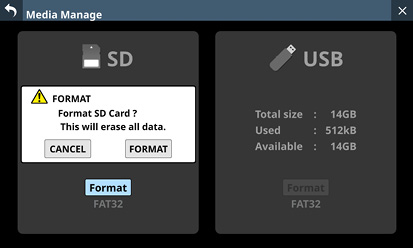
When formatting a USB flash drive, a window for selecting the file system to use for formatting will open.
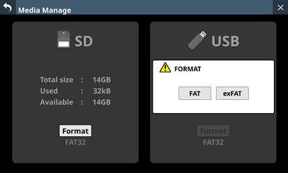
Tap the button for the file system to use for formatting.
NOTE
When formatting an SD card, the file system used for formatting will be selected automatically according to the capacity of the loaded SD card (FAT32 for SDHC cards and exFAT for SDXC cards).
2.Tap the Format button to start formatting.
The following screen will appear during formatting.
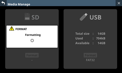
This window will close when formatting completes.
This screen shows information about system firmware, various devices, application versions and update requirements.
Tap Menu Screen > System Setup > Version Information to open the Version Information Screen.
.jpg)
System version
This shows information about the current Sonicview system firmware version.
Names of various devices and applications
This shows the names of the Dante device built into the Sonicview, slot cards, supported applications and SB-16D units.
Status
This shows whether each device/application requires an update.
“OK” will be shown if the current version is the same as the required version.
In this case, there is no need to update that device/application.
“![]() Update Required.” Will be shown if the current version is lower than the required version.
Update Required.” Will be shown if the current version is lower than the required version.
In this case, that device/application might not function properly.
Update the firmware/software of that device/application.
“![]() Please check the latest system version of Sonicview.” will appear if the current version is higher than the required version.
Please check the latest system version of Sonicview.” will appear if the current version is higher than the required version.
In this case, the firmware of the Sonicview might be able to be updated. When only devices or applications have been updated, however, updating the Sonicview firmware is not necessary.
Check the TASCAM website for information about the latest Sonicview firmware.
Sonicview 16XP
https://tascam.com/us/product/sonicview_16xp/support
Sonicview 24XP
https://tascam.com/us/product/sonicview_24xp/support
NOTE
If one of the following messages appears in the Status field, this is a notification that the device, application or main unit requires an update, so an ![]() icon will appear with System Setup menu items and Version Information submenu items on the Menu Screen.
icon will appear with System Setup menu items and Version Information submenu items on the Menu Screen.
![]() Update Required.
Update Required.
![]() Please check the latest system version of Sonicview.
Please check the latest system version of Sonicview.
Required ver
This shows information about the device/application version required by the current Sonicview system firmware.
 Current ver
This shows current version information for each device/application.
See “TASCAM Sonicview Control” for the current version information of this dedicated application.
Use “TASCAM Sonicview USB” installed on a Windows computer to check the current version information of the TASCAM Sonicview USB for Windows software.
Check Dante Controller for the Dante Module version information of an IF-DA64 (Dante) card.
DETAIL button
Tap this button to open the Version Information Details Screen that shows detailed information about the system firmware versions and build numbers, as well as information about cards installed in SLOT 1 and SLOT 2.
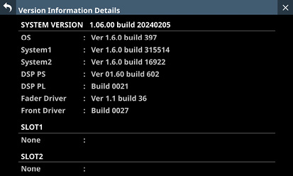
Scrollbar display
This is shown if all the names of the Dante device built into the Sonicview, slot cards, supported applications and SB-16D units do not fit on the screen.
Drag the scrollbar to scroll the screen. The list can also be scrolled by swiping up and down as well as by turning LCD knob 8.
ATTENTION
When conducting firmware updates, use a USB flash drive or SD card that has been formatted with a file system supported by this unit (FAT32 or exFAT). We recommend formatting the USB flash drive or SD card with this unit before using it. (See “Media Manage Screen”.)
If a snapshot created on a unit with MAIN firmware version 1.1.0 or later is recalled by a unit with firmware version 1.0.x, proper operation will not be possible, so the following restrictions apply.
Downgrading the MAIN firmware to version 1.0.x is not possible.
Snapshot/All System Data created on units with MAIN firmware version 1.1.0 or later cannot be imported/restored on units with firmware version 1.0.x. (Snapshot/All System Data created by units with firmware version 1.0.x can be imported/restored on units with firmware version 1.1.0 or later.)
1.Download the latest firmware from the TASCAM website with a computer.
Sonicview 16XP
https://tascam.com/us/product/sonicview_16xp/support
Sonicview 24XP
https://tascam.com/us/product/sonicview_24xp/support
Decompress the downloaded file if it is in ZIP format or another compressed file type.
2.Copy only the downloaded/decompressed firmware file to the root directory (top level) of a USB flash drive or SD card from the computer.
3.Insert the USB flash drive or SD card prepared in step 2 into the USB port or SD card slot on the top panel.
4.Tap Menu Screen > System Setup > Firmware Update to open the Firmware Update Screen.
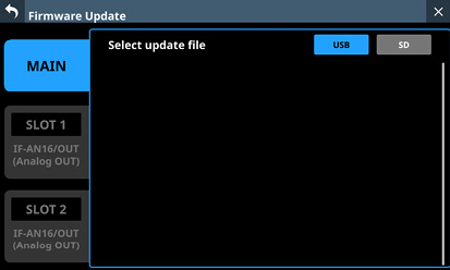
5.Tap the tab for the device to be upda ted.
|
Device |
Explanation |
|
MAIN |
Update the firmware of the main unit. |
|
SLOT 1 |
Update the firmware of the expansion card installed in SLOT 1. |
|
SLOT 2 |
Update the firmware of the expansion card installed in SLOT 2. |
NOTE
Tabs will not be shown for slots that do not have an expansion card installed.
6.Tap the USB or SD button at the top right of the screen to select the media connected in step 3.
When the USB flash drive or SD card has been recognized and the firmware update file has been verified, the following screen will appear.
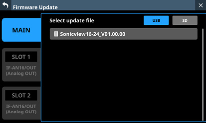
NOTE
The screen above shows a list of firmware update files in the root folder of the connected USB flash drive or SD card drive. The firmware copied in step 2 above should also be shown.
A maximum of five lines of firmware can be shown at the same time. If there are more files than can be shown on the display at once, swipe the list up or down to scroll it.
The screen shown above is an example. The actual appearance will differ.
7.Tap the firmware to use for the update to select it. This will automatically prepare the firmware updater and the screen shown below will appear.
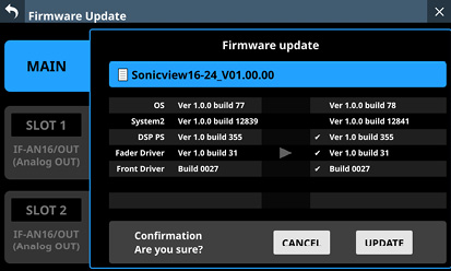
The number of the current version is shown on the left and the update version is shown on the right.
NOTE
The screen shown above is an example. The actual appearance will differ.
8.When an update confirmation message appears, tap the UPDATE button.
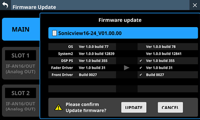
NOTE
The UPDATE button will not be shown if updating is not necessary.
Tap the CANCEL button to cancel updating and return to the list of update files.
9.When an update confirmation message appears again, tap the UPDATE button. The startup screen will be shown briefly and then updating will start.
ATTENTION
Be careful not to let the power be interrupted during the update.
If the power is interrupted during the update, the unit might become unstartable.
10.When the update completes, the following screen will appear.
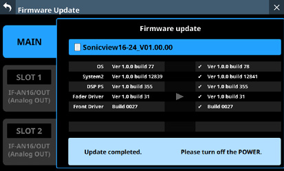
11.Use the POWER switch on the back of the unit to restart it.
ATTENTION
Even though a RESTART button is shown in MAIN firmware versions 1.0.2 and earlier, do not tap it. Always use the POWER switch on the rear panel to restart the unit.
12.After the unit restarts, confirm that the latest firmware is being used (see “Version Information Screen”).
This completes updating the unit.
13.Delete the firmware update file from the USB flash drive or SD card.
This unit includes a 2-track WAV recorder (SD card) and a 2-track WAV/MP3/AAC player (SD card/USB flash drive).
The recording file formats are as follows.
WAV: 48/96 kHz, 24-bit, 2-channel
Recording will be at the sampling frequency set with the Sync Clock button () on the SYNC CLOCK Screen. (See “Setting the sampling frequency”.)
The playback file formats are as follows.
BWF/WAV: 48/96 kHz, 16/24-bit, 2-channel
MP3: 44.1/48 kHz, 32–320 kbps, 2-channel
AAC: 44.1/48 kHz, 64–320 kbps, 2-channel
SD cards formatted by this unit are optimized to improve performance during recording. Use this unit to format the SD cards to be used with it. (See “Media Manage Screen”.)
Errors might occur when recording with this unit using an SD card formatted by a computer or other device.
SD cards and USB flash drives used by this unit
Lists of SD cards and USB flash drives that have been confirmed for use with this unit can be found on the TASCAM website.
Sonicview 16XP
https://tascam.com/us/product/sonicview_16xp/support
Sonicview 24XP
https://tascam.com/us/product/sonicview_24xp/support
Please use SD cards and USB flash drives included in these lists.
Control the built-in recorder/player on this screen.
Tap Menu Screen > Recorder/Player menu > Recorder/Player to open this screen.
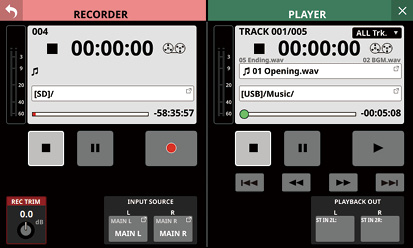
.jpg)
Recorder transport status
This icon shows the transport status.
Total number of recorded tracks
This shows the total number of recorded file tracks.
NOTE
The total number of tracks that can be recorded to one folder is 999. “Rec Limit” will be shown in the recording folder name area for folders that already have 999 tracks or that contain files with names ending “999.wav” and recording will no longer be possible.
Switch to a different folder to record.
Elapsed recording time
This shows the elapsed recording time.
If no media has been loaded, “--:--:--” will be shown.
Recording input level meters
These shows the levels input to the internal recorder.
Media capacity bar
This shows the amount of space already used as a proportion of the total space on the media.
As recording progresses, the bar extends from the left to the right.
RECORDER information area
When recording, the background of this area becomes light red to show clearly that recording is in process.
Tape reel icon
When recording, the tape reel icon turns to show clearly that the unit is operating.
Recording file name
When recording and when recording is paused, this shows the name of the file being recorded.
After recording is stopped, this shows the name of the file that was last recorded.
The recording file name format is as follows.
YYYYMMDD_nnn.wav
YYYY: Year
MM: Month
DD: Day
nnn: 3-digit number
NOTE
Nothing will be shown immediately after the unit starts up, media is loaded or a folder is selected.
Recording folder name
This shows the path of the recording destination folder.
Tap this area to open the BROWSE screen where the recording destination folder can be selected. (See “BROWSE Screen for recording folder selection”.)
“No Media” is shown when no SD card is loaded.
“No free space” is shown when the SD card does not have space.
“Unrecognized” is shown when the SD card cannot be recognized. Tap this message to open the Media Manage Screen. (See “Media Manage Screen”.)
NOTE
If the total number of files and subfolders in the folder exceeds 999, files and folders might not be shown correctly.
Remaining recording time
This shows the remaining available recording time of the media.
If recording is not possible because no media has been loaded or the media does not have open space, for example, “--:--:--” will be shown.
Transport operation buttons/indicators
These control the internal recorder.
|
|
When recording, tap this to stop recording. When recording is stopped, this button will be highlighted white. |
|
|
When recording, tap this to pause recording. When recording is paused, this button will be highlighted white. |
|
|
When recording is stopped, tap this to start recording. When recording is paused, tap this to resume recording. When recording or paused, this button will be highlighted light red. |
REC TRIM knob
Turn LCD knob 1 to adjust the trim value of the level input to the recorder.
Range: −20.0 dB – +20.0 dB (in 0.1 dB steps, default: 0.0 dB)
INPUT SOURCE setting buttons
These show the names of the input sources.
The top line of the button shows the FIXED MODULE LABEL.
The bottom line of the button shows the USER MODULE LABEL.
If the USER MODULE LABEL is undefined, the FIXED MODULE LABEL will be shown. (See “MODULE LABEL page”.)
Nothing will be shown if no input source is assigned.
Tap these buttons to open the RECORDER INPUT SOURCE SELECT Screen.
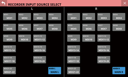
MIX 1–22 and MAIN L/R signals can be selected as inputs to the left and right channels of the recorder (default: MAIN L/R).
.jpg)
Playback transport status
This icon shows the transport status.
Playback track number/number of tracks
This shows the number of the currently playing track/total number of tracks.
Elapsed playback time
This shows the elapsed time from the beginning of the track.
If no media has been loaded, “--:--:--” will be shown.
Playback mode
This shows the playback mode.
Tap this area to open a window where the playback mode can be set.
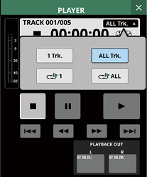
|
Icon |
Meaning |
|
|
Single playback |
|
|
Folder playback (default) |
|
|
Single repeat playback |
|
|
Folder repeat playback |
Tap a button in the window to switch to that playback mode and close the window.
Playback output level meters
This shows the levels output from the player.
Time Bar
This shows the current playback position relative to the length of the take.
Drag the knob on the bar to change the playback position.
Tape reel icon
When playing, the tape reel icon turns to show clearly that the unit is operating.
Names of files before and after the current playback file
The name of the file just before the current playback file is shown on the left side.
The name of the file just after the current playback file is shown on the right side.
Name of current playback file
This shows the name of the current playback file.
Tap this area to open the BROWSE screen where the media, folder and file used for playback can be selected. (See “BROWSE screen for playback media, folder and file selection”.)
Playback folder name
This shows the name of the media and the folder path used for playback.
Tap this area to open the BROWSE screen where the media, folder and file used for playback can be selected. (See “BROWSE screen for playback media, folder and file selection”.)
Remaining playback time
This shows the remaining time of the playing track.
Transport operation buttons/indicators
These control the player.
|
|
Tap this when the player is playing to stop playback. When the player is stopped, this button will be highlighted white. |
|
|
When the player is stopped or playing, tap this button to pause playback. When the player is paused, this button will be highlighted white. |
|
|
Tap this when the player is stopped or paused to start playback. When playing, this button will be highlighted green. |
|
|
When the player is stopped, playing back or paused, tap these buttons to start searching forward/backward. Pres and hold one of these to keep searching while it is being touched.
|
|
|
Tap this when the player is stopped to skip to the previous/next file. Tap the Press the Tap the |
PLAYBACK OUT setting buttons
These show the fixed module and user module labels of the input modules to which the player outputs are assigned.
Nothing will be shown if no player output is assigned.
If they have been assigned to multiple input modules, they will be shown in order from the lowest number.
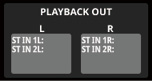
BROWSE Screen for recording folder selection
Tap the recording folder name in the RECORDER Section to open the BROWSE screen where the recording destination folder can be selected.
Move to the desired existing folder or new folder to use for recording, and tap the Set REC FOLDER button (![]() ) to set that folder as the recording folder.
) to set that folder as the recording folder.
.jpg)
Example of folder set as the recording folder
.jpg)
SD card root directory example
NOTE
Recording to USB flash drives is not possible. Only SD cards can be used as recording media.
If the total number of files and subfolders in the folder exceeds 999, files and folders might not be shown correctly.
![]() button
button
Tap this button to return to the RECORDER/PLAYER Screen.
Media name
This is the name of the media that is being shown.
Recording folder indicator
This indicates that the folder being shown is set as the recording folder.
PLAY FOLDER indicator
This indicates that the folder being shown is set as the playback folder.
![]() button
button
Tap this button to open a menu window that enables various operations at the current level.
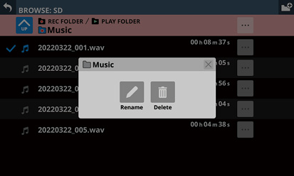
|
Menu item |
Explanation |
|
Rename |
This opens a screen where the name of the current folder can be changed. |
|
Delete |
This deletes the current folder. |
This operation is not possible during recording and playback.
Tapping this when the SD card level is open will show information about the media.
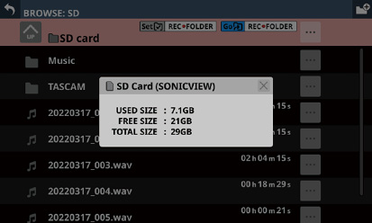
SD card volume name
Various SD card capacity data
![]() button
button
Use this button to create a new folder on the level being shown.
Tap this button to open a screen where the name of the folder being created can be input.
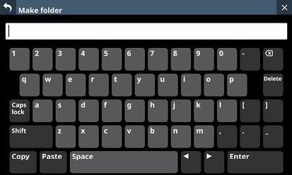
The combination of characters input can be changed depending on the status of the Caps lock and Shift keyboard buttons on the Make Folder Screen. See “Changing the keyboard keys” for details about changing the keyboard.
Level change button
Tap the ![]() button to show the folder level one step above the current level.
button to show the folder level one step above the current level.
NOTE
This will be gray when the current level is the “SD Card”, which is the top level.
Level name
This shows the icon and name of the level that is currently open.
Set REC FOLDER button
Tap this button to set the folder being shown as the recording folder. When set as the recording folder, this button and the Go REC FOLDER button () disappear and the recording folder () indicator appears.
For details about how to make recording folder settings, see “Setting the recording folder”.
Go REC FOLDER button
Tap this button to open the recording folder.
Folder list
This shows the folders on the current level in name order.
Tap this area to enter the tapped folder.
File list
This shows the names and lengths of playable files on the current level in name order.
![]() buttons
buttons
Tap one of these buttons to show various information about the file to the left and open a menu that enables the following operations.
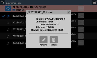
|
Menu item |
Explanation |
|
Rename |
This opens a screen where the name of the file to the left of the button can be changed. |
|
Delete |
This deletes the file to the left of the button. |
This operation is not possible during recording and playback.
Tap a button to the left of a folder to open a menu that enables the following operations on that folder.
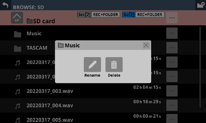
|
Menu item |
Explanation |
|
Rename |
This opens a screen where the name of the folder to the left of the button can be changed. |
|
Delete |
This deletes the folder to the left of the button. |
This operation is not possible during recording and playback.
Scrollbar
This appears when the number of folders and files exceeds the amount that can be shown on the display at the same time.
Drag the scrollbar to scroll the screen. The file list can also be scrolled by swiping it up and down as well as by turning LCD knob 8.
BROWSE screen for playback media, folder and file selection
Tap the name of the playback folder or playback file in the PLAYER section to open the BROWSE screen where the media, folder and file used for playback can be selected.
Move to the folder on the media that contains the desired file for playback, and tap the Set PLAY FOLDER button (![]() ) to set that folder on the selected media as the playback folder.
) to set that folder on the selected media as the playback folder.
.jpg)
Example of folder set as the playback folder
.jpg)
SD card root directory example
.jpg)
Example of mixer Root directory for selecting media
NOTE
If the total number of files and subfolders in the folder exceeds 999, files and folders might not be shown correctly.
![]() button
button
Tap this button to return to the RECORDER/PLAYER Screen.
Media name
This is the name of the media that is being shown.
PLAY FOLDER indicator
This indicates that the folder being shown is set as the playback folder.
Recording folder indicator
This indicates that the folder being shown is set as the recording folder.
![]() button
button
Tap this button to open a menu window that enables various operations at the current level.
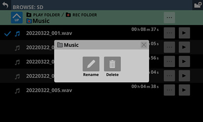
|
Menu item |
Explanation |
|
Rename |
This opens a screen where the name of the current folder can be changed. |
|
Delete |
This deletes the current folder. |
This operation is not possible during recording and playback.
Tapping this when a media root level is open will show information about the media.
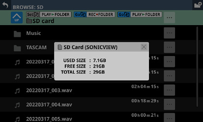
Media volume name
Various media capacity data
![]() button
button
Use this button to create a new folder on the level being shown.
Tap this button to open a screen where the name of the folder being created can be input.
The combination of characters input can be changed depending on the status of the Caps lock and Shift keyboard buttons on the Make Folder Screen. See “Changing the keyboard keys” for details about changing the keyboard.
Level change button
Tap the ![]() button to show the folder level one step above the current level.
button to show the folder level one step above the current level.
NOTE
This will be gray when the Root (highest) level is open.
Level name
This shows the icon and name of the level that is currently open.
Set PLAY FOLDER button
Tap this button to set the folder being shown as the playback folder.
When set as the playback folder, this button and the Go PLAY FOLDER button () disappear and the PLAY FOLDER indicator () appears.
For details about setting the playback folder, see “Setting the playback folder”.
Go REC FOLDER button
Tap this button to open the recording folder.
Go PLAY FOLDER button
Tap this button to open the playback folder.
Playback selection marks
Tap this area to select audio files and make them subject to playback by adding check marks (![]() ).
).
Folder list
This shows the folders on the current level in name order.
Tap this area to enter the tapped folder.
File list
This shows the names and lengths of playable files on the current level in name order. Tap this area to select audio files and make them subject to playback by adding check marks (![]() ).
).
![]() buttons
buttons
Tap one of these buttons to show various information about the file to the left and open a menu that enables the following operations.
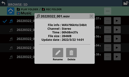
|
Menu item |
Explanation |
|
Rename |
This opens a screen where the name of the file to the left of the button can be changed. |
|
Delete |
This deletes the file to the left of the button. |
This operation is not possible during recording and playback.
Tap a button to the left of a folder to open a menu that enables the following operations on that folder.
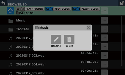
|
Menu item |
Explanation |
|
Rename |
This opens a screen where the name of the folder to the left of the button can be changed. |
|
Delete |
This deletes the folder to the left of the button. |
This operation is not possible during recording and playback.
![]() buttons
buttons
Tap one of these buttons to select an audio file, make it subject to playback, and start playing it. The button will become highlighted green.
Tap the button that is highlighted to stop playing the audio file.
Scrollbar
This appears when the number of folders and files exceeds the amount that can be shown on the display at the same time.
Drag the scrollbar to scroll the screen. The file list can also be scrolled by swiping it up and down as well as by turning LCD knob 8.
Media list
This shows the media loaded in the unit.
Tap this area to open the tapped media.
Media menu buttons (![]() )
)
Tap these buttons to show information about the media to the left.
Media volume name
Various media capacity data
1.Tap Menu Screen > Recorder/Player menu > Recorder/Player to open the RECORDER/PLAYER Screen.
2.Tap the recording folder name () in the RECORDER Section to open the RECORDER BROWSE Screen.
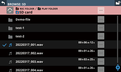
3.Tap the folder to be set as the recording folder.
This opens the screen for the tapped folder.
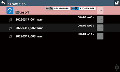
4.Tap the Set REC FOLDER button ().
This sets it as the recording folder, and “REC FOLDER” appears.
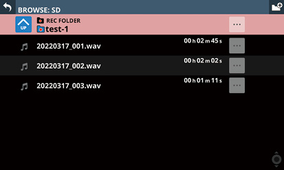
1.Tap Menu Screen > Recorder/Player menu > Recorder/Player to open the RECORDER/PLAYER Screen.
2.Tap the name of the current playback file () or the playback folder name () in the PLAYER Section to open the PLAYER BROWSE Screen.
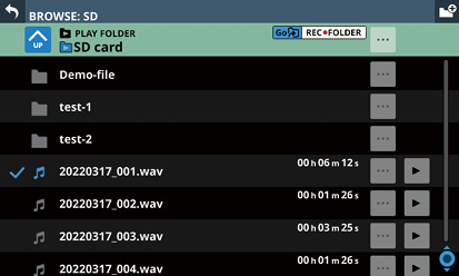
3.Tap the folder to be set as the playback folder.
This opens the screen for the tapped folder.
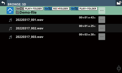
4.Tap the Set PLAY FOLDER button ().
This sets it as the playback folder, and “PLAY FOLDER” appears.
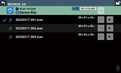
Installing the dedicated software
To use this unit as a USB audio interface with a Windows computer, dedicated software must be installed on the computer.
Download the latest software from the product page on the TEAC Global Site (https://teac-global.com/).
Installing the dedicated software will install a driver and the TASCAM Sonicview USB application.
ATTENTION
Before starting to install software, quit other applications.
NOTE
With macOS, the standard OS driver will be used, so there is no need to install any software.
Installing the Windows dedicated software
Follow the procedures below to install the Windows dedicated software.
ATTENTION
Complete installation of the Windows dedicated software on the computer before connecting the unit to it with the USB cable.
If you connected the unit to the computer using the USB cable before installing the Windows dedicated software and the “Found New Hardware Wizard” launched, close the Wizard and disconnect the USB cable.
Windows dedicated software installation procedures
1.Download the latest Windows software from the TASCAM website and save it on the computer to be used with the unit.
Sonicview 16XP
https://tascam.com/us/product/sonicview_16xp/support
Sonicview 24XP
https://tascam.com/us/product/sonicview_24xp/support
2.Uncompress the saved software (zip file) on the computer desktop or another location.
3.Double-click the “TASCAM Sonicview USB.exe” file in the folder that appears after uncompression to launch the installation software.
ATTENTION
If you open a zip file without decompressing it and doubleclick the “TASCAM Sonicview USB.exe” file in the folder that opens, installation will not start. Right-click the zip file and select “Extract All”, for example, to decompress it and then try again.
4.When a Security Warning or User Account Control screen appears, click the “Yes” button.
5.Read the contents of the User License Agreement, and select “I accept the agreement” if you agree to the terms. Then, click the “Next>” button.
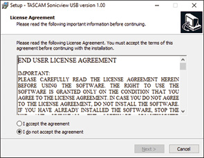
6.Next, click the “Install” button.
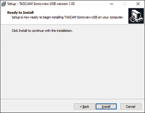
7.The following screen appears when installation has completed.
Click the “Finish” button.
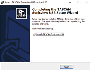
After installation completes, the installed TASCAM Sonicview USB software will launch.
NOTE
The first time you connect the unit by USB to the computer after installing the software, installation of the device driver will be executed. Some time might be necessary before the unit is recognized because Windows Update will be automatically searched at this time. If the unit is still not recognized after a while, open the software installation screen from the notification area at the bottom right of the computer display, and click “Skip obtaining driver software from Windows Update” to stop the search.
Uninstalling the dedicated software
NOTE
Normally, there is no need to uninstall the dedicated software. Follow these procedures if a problem occurs or you no longer intend to use the unit with the computer.
Uninstalling the Windows dedicated software
1.Open the “Uninstall or change a program” screen using the procedures for the operating system being used (Windows 11/Windows 10).
2.Select “TASCAM Sonicview USB ” from the list, and double-click it.
3.Then, follow the instructions that appear on the screen.
Opening the dedicated software
The dedicated TASCAM Sonicview USB software can be opened in the following manner.
From the “Start” menu select “TASCAM Sonicview USB” under “TASCAM”.
After startup, the following message will be shown.
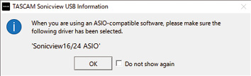
Click the OK button to open the following window.
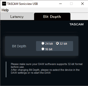
The amount of latency for audio input and output signals transferred to and from the computer can be adjusted using the ASIO driver.
Smaller values result in less audio signal delay, but require high-speed processing by the computer.
If the processing cannot keep up, for example, due to other system operations, clicking and popping noises might occur and the audio signal might even drop out.
Increasing the value will stabilize operation and suppress negative effects on audio signals, but the delay in audio signal transfer between the unit and the computer will increase.
The amount of latency for this unit can be adjusted according to use conditions.
Changes to this setting will be applied immediately to the ASIO driver.
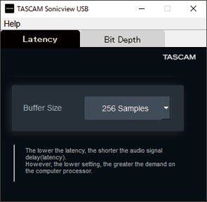
Default: 256 samples
NOTE
On macOS, adjust this with application settings.
If clicking and popping noises or dropouts, for example, occur in the audio signal even after making the above input latency and buffer size adjustments, reducing the bit depth of the audio data could stabilize computer operation, depending on system conditions.
Setting this on Windows
The bit depth for audio data can be set to 32 bit, 24 bit or 16 bit. (default: 32bit)
NOTE
Changes to this setting will be applied immediately to the ASIO driver. Doing just this, however, will not apply it to the DAW. See the precautions below.
This setting is only applied to the ASIO bit depth. For procedures to change the WDM bit depth, see “Setting procedures for use with OBS Studio and other streaming applications”.
Setting this on macOS
1.Open the Audio MIDI Setup app from the Applications folder.
2.Set the Sonicview as the Sound Input and Sound Output device.
3.Change the Format for Input and Output.
Precautions with both Windows and macOS
Confirm that the DAW application being used supports 32-bit before using the 32-bit setting.
After changing the bit depth, reselect the device in the DAW settings or restart the DAW software.
1.Use a USB cable to connect the computer and this unit.
2.Open the Control Panel on the Windows computer.
NOTE
Follow these procedures to open the Control Panel.
Windows 11
Click the Windows Start button, and from “All apps” click “Windows Tools” and then double-click “Control Panel”.
Windows 10
Click the Windows Start button, and under “Windows System”, click “Control Panel”.
3.Double-click “Sound” in the Control Panel.
NOTE
If the Control Panel is set to be viewed as icons, a “Sound” icon will appear.
4.On the “Playback” page, right-click “Sonicview 16/24”, and click “Set as Default Device” in the pop-up menu that appears.
When you do this, the green check mark appears next to the selected device.
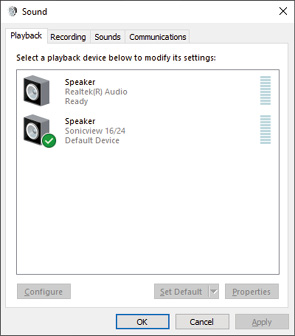
Windows 10 screen
NOTE
Set the default device according to the device being used on the Recording tab in the same manner as on the Playback tab.
5.After completing the setting, click the “OK” button.
6.Launch Windows Media Player and play an audio file to input the playback sound from the computer to USB IN 1 and 2 on the Sonicview 16XP/24XP.
NOTE
If you change the setting while Windows Media Player is running, the software will not recognize that the device has been changed. In this case, restart Windows Media Player.
if you still cannot hear sound after making the settings and completing the procedures above, restart the computer.
If you make this setting, sound will be output through this unit, but no sound will be output from the computer’s speakers or headphone jack.
Simultaneous ASIO/WDM playback
The driver for this unit can simultaneously play ASIO output from a DAW and WDM output from Windows Media Player, for example. The sample rates of both sources must be set to the same value for simultaneous playback to be possible. Moreover, the sample rate must also be set to the same value for both playback and recording in the Windows Sound Properties.
When the sample rates are the same
Example: Windows (WDM) at 48000 Hz, ASIO at 48000 Hz
The Windows audio and ASIO sound are mixed and played simultaneously.
When the sample rates are different
Example: Windows (WDM) at 48000 Hz, ASIO at 96000 Hz
Only sound from a DAW and other ASIO sources are output. Sound from Windows Media Player and other WDM sources are not output.
When the DAW is shut down, for example, and output from ASIO sources stops, sound from Windows Media Player and other WDM sources will become audible.
Setting procedures for use with OBS Studio and other streaming applications
Conduct the procedures in this document before launching the streaming application.
Windows computer sound settings
Set the input and output device, sampling frequency, bit rate, and number of channels according to the setup.
1.Use a USB cable to connect the computer and this unit.
2.Open the Sound Settings screen.
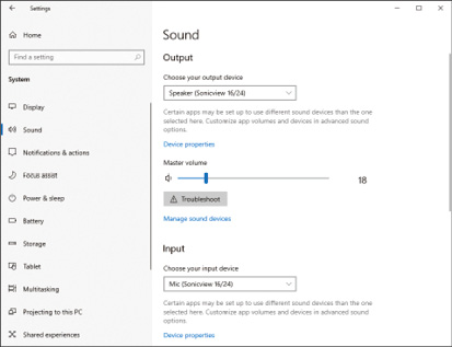
NOTE
This can also be opened by right-clicking the sound icon at the bottom right of the desktop screen, selecting “Open Sound settings” and then selecting “Sound”.
3.Set the output device to “Speakers (Sonicview 16/24)”.
4.Set the input device to “Microphone (Sonicview 16/24)”.
5.Click “Sound Control Panel” to open the Sound window.
6.Open the Recording tab, and select “Sonicview 16/24”.
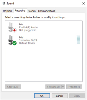
7.Click “Properties” for “Sonicview 16/24” to open the Microphone Properties screen.
8.Open the Advanced tab, and set the Default Format.
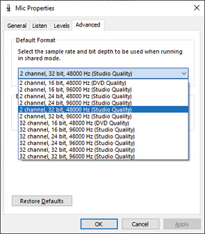
Select a 2-channel setting when using OBS Studio or another application that supports 2-channel audio devices. Otherwise, select a 32-channel setting.
Set the “Default Format” sample rate to match the sample rate of the application being used to stream
9.Open the Playback tab, and select “Speakers (Sonicview 16/24)”.
10.Click “Properties” for “Speakers (Sonicview 16/24)” to open the Speakers Properties Screen.
11.Open the Advanced tab, and set the Default Format.
Set the sample rate and bit depth for the Default Device on the Play tab to the same values set on the Record tab.
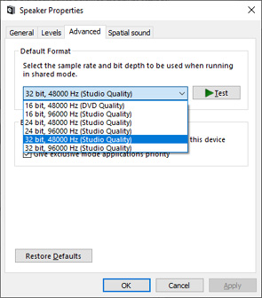
12.Launch the streaming application, and proceed with streaming and other functions.
13.After completing streaming, restore the settings to multichannel to use multiple channels with other applications as necessary.
In step 7, set the Microphone Properties to 32-channel.
NOTE
For Sonicview 16XP and Sonicview 24XP, IF-MTR32 is pre-installed in SLOT1.
Multitrack recording with this unit can be enabled by installing an IF-MTR32 (multitrack recording) card in SLOT 1 or SLOT 2 on the rear panel.
The IF-MTR32 is a multitrack recorder (MTR) that is capable of recording up to 32 tracks (when the sampling rate is 48 kHz).
The recording/playback formats are as follows.
File format: BWF/WAV (recording is always BWF), monophonic
Sampling Rate: 48 kHz, 96 kHz
Quantization bit depth
When recording: 24-bit or 32-bit
When playing: 16-bit*, 24-bit or 32-bit
*Quantization bit depth: 16-bit
Playback of imported files with this bit depth is supported only when the MTR operation mode is LIVE RECORDING MODE or VIRTUAL SOUND CHECK MODE. Recording at 16-bit is not supported. Moreover, punching in/out is not possible with imported 16-bit files, so they cannot be selected when the MTR operation mode is OVERDUB MODE.
Recording will be at the sampling frequency set on the MULTI TRACK RECORDER - MENU Screen. (See “ Sampling Rate (Max Tracks) buttons”.)
ATTENTION
Only one IF-MTR32 card can be used at a time.
If two IF-MTR32 cards are installed, only the one in SLOT 1 can be used.
|
File format used |
Media capacity |
|||
|
64GB |
128GB |
256GB |
512GB |
|
|
48kHz/24-bit/ 32-track |
3h 49m |
7h 41m |
15h 23m |
30h 49m |
|
48kHz/32-bit/ 32-track |
2h 52m |
5h 45m |
11h 32m |
23h 07m |
|
96kHz/24-bit/ 16-track |
3h 50m |
7h 41m |
15h 24m |
30h 50m |
|
96kHz/32-bit/ 16-track |
2h 52m |
5h 46m |
11h 33m |
23h 08m |
The recording times shown above are estimates. They might differ depending on the media used.
The recording times shown above are not continuous recording times, but rather they are the total possible recording times for the media.
NOTE
If the size of a recording file for a track exceeds 4 GB during recording, a new take will be created and recording will continue in that take.
SD cards formatted by an IF-MTR32 are optimized to improve performance during recording. Use an IF-MTR32 to format SD cards to be used with an IF-MTR32. (See “ Format buttons”.)
Errors might occur when recording with an IF-MTR32 using an SD card formatted by a computer or other device.
SD cards used by IF-MTR32 units
A list of SD cards that have been confirmed for use with the IF-MTR32 can be found by accessing the TASCAM website.
Sonicview 16XP
https://tascam.com/us/product/sonicview_16xp/support
Sonicview 24XP
https://tascam.com/us/product/sonicview_24xp/support
Please use SD cards included in this list.
With this multi track recorder (MTR), groups of files recorded at the same time are called “takes” and folders that contain recorded takes are called “projects”.
This MTR has the following three operation modes.
The operation mode can be changed by tapping the MTR operation () button on the MULTI TRACK RECORDER Screen.(See “Switching MTR operation mode”.)
LIVE RECORDING MODE
In this mode, takes can be recorded one at a time and multiple takes can be played back consecutively in a project.
VIRTUAL SOUND CHECK MODE
The routing with the MTR in this mode is limited to virtual sound check routing.
When recording, sound sources for virtual sound checks are recorded by recording the DIRECT OUT from the corresponding INPUT modules.
When the SOUND CHECK button appears highlighted, MTR playback output starts for the INPUT of the corresponding channels, enabling a virtual sound check.
NOTE
In this mode, the DIRECT OUT POINT is set to “INPUT”.
OVERDUB MODE
The routing with the MTR in this mode is limited to INSERT SEND/RETURN.
In this mode, overdubbing, including punching in/out, is possible with individual takes that have already been recorded.
Use this screen to make settings and show the status of the IF-MTR32 (multitrack recorder) card installed in SLOT 1 or SLOT 2.
Tap Menu Screen > Recorder/Player menu > Multi Track Recorder to open this screen. This screen can also be opened by tapping “Recorder/Player: MTR” shown for the slot with the IF-MTR32 installed on the SLOT SETUP Screen.
NOTE
When the IF-MTR32 card is initializing, the “Multi Track Recorder” sub menu item will be shown in gray on the Menu Screen, and the MULTI TRACK RECORDER Screen will not open even if it is tapped. Wait a while until it becomes usable.
When in LIVE RECORDING MODE or VIRTUAL SOUND CHECK MODE
.jpg)
Screen appearance in LIVE RECORDING MODE
When in OVERDUB MODE
.jpg)
Project Name
This shows the name of the currently open project.
Tap this area when the MTR is stopped to open the BROWSE MTR Screen, which shows a project list. (See “Selecting projects”.)
AUTO ROUTING button
Tap this button when the MTR is stopped to open an AUTO ROUTING confirmation message. (See “Using the AUTO ROUTING function”.)
Take Name
This shows the name of the currently open take.
Tap this area when the MTR is stopped to open the BROWSE MTR Screen, which shows a list of takes in the current project. (See “MULTI TRACK RECORDER - BROWSE Screen”.)
This shows the current MTR operation mode.
LIVE RECORDING MODE
VIRTUAL SOUND CHECK MODE
OVERDUB MODE
Tap this button when the MTR is stopped to open the MTR operation mode switching menu. (See “Using the AUTO ROUTING function”.)
MTR menu button (![]() )
)
Tap this button when the MTR is stopped to open the dedicated MTR Menu Screen. (See “MULTI TRACK RECORDER - MENU Screen”.)
Meters and REC READY/INPUT MONITOR indicator area
This area shows the meters and REC READY/INPUT MONITOR states of each track.
32 tracks are shown when the Sampling Rate (Max Tracks) button () setting is “48kHz/32tracks” on the MULTI TRACK RECORDER - MENU Screen, and 16 tracks are shown when this is set to “96kHz/16tracks”. (See “MULTI TRACK RECORDER - MENU Screen”.)
Each meter has an overload indicator at its top. They will appear to light red when the signal level reaches or exceeds −0.00026 dBFS (16-bit full-scale value).
When a level overload occurs, the entire bar meter will light red.
The area below −60 dBFS at the bottom of the level meters will light when above −70 dBFS.
When REC READY is on, the ![]() icon below the meter will appear red (
icon below the meter will appear red (![]() ).
).
When INPUT MONITOR is on, the ![]() icon below the meter will appear blue (
icon below the meter will appear blue (![]() ).
).
Tap this area to open a REC READY / INPUT MONITOR settings window below the meters for the group of 8 tracks in the area tapped. (See “REC READY/INPUT MONITOR settings”.)
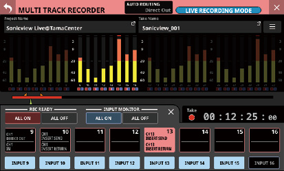
IN/OUT mark display area
The IN (![]() ) and OUT (
) and OUT (![]() ) points in the take are shows above the time progress bar.
) points in the take are shows above the time progress bar.
Progress bar
When recording, the amount of space already used as a proportion of the total space on the media is shown as a red bar. As recording progresses, the red bar extends from the left to the right.
When playing, the current playback position relative to the length of the project or take being played (depending on the time display mode) is shown as a green bar. Dragging it changes the playback position.
Mark indicator area
The marks () in the take are shown below the progress bar.
When the time display mode is PROJECT, only marks in the take that is currently playing are shown.
IN/OUT point setting area
Use this area to set IN/OUT points and the repeat mode.
.jpg)
SET IN button
When tapped, this sets the IN point at the current recording/playback time. If an IN point has already been set, tapping this will reset the IN point.
This will be used as the I-O repeat point when the MTR operation mode is LIVE RECORDING MODE or VIRTUAL SOUND CHECK MODE.
This will be used as either the I-O repeat point or the auto punch in point when the MTR operation mode is OVERDUB MODE.
SET OUT button
When tapped, this sets the OUT point at the current recording/playback time. If an OUT point has already been set, tapping this will reset the OUT point.
This will be used as the I-O repeat point when the MTR operation mode is LIVE RECORDING MODE or VIRTUAL SOUND CHECK MODE.
This will be used as either the I-O repeat point or the auto punch out point when the MTR operation mode is OVERDUB MODE.
CLEAR button
This clears the IN/OUT points.
Repeat mode setting button
This sets the repeats playback function mode.
When the MTR operation mode is LIVE RECORDING MODE or VIRTUAL SOUND CHECK MODE, tap this to cycle through these options: OFF, 1, ALL and I-O.
When the MTR operation mode is OVERDUB MODE, tap this to cycle through these options: OFF, 1, and I-O. Repeat playback is not possible, however, when the AUTO PUNCH button is set to “ON”.
|
Repeat mode |
Function |
|
|
Playback will not be repeated. |
|
|
The entire take that is currently selected will be played repeatedly. |
|
|
The entire project will be played repeatedly. This can be selected when the MTR operation mode is LIVE RECORDING MODE or VIRTUAL SOUND CHECK MODE. |
|
|
Playback will be repeated between the IN and OUT points. |
NOTE
Set the in and out points at least 200 ms apart. If the interval is less than 200 ms, the following message will appear and the later point will not be set.
|
Invalid I/O. Interval too short. |
Trying to set the out point before the in point or the in point after the out point will fail and the following message will appear. Set the in point so that it is before the out point.
|
Invalid I/O. Please set IN and OUT in order. |
If the MTR operation mode is switched to OVERDUB MODE when the repeat mode is set to ALL, the repeat mode will be automatically switched to OFF.
AUTO REC button and indicator
When the MTR is stopped, tap this button to open the MULTI TRACK RECORDER - MENU Screen where automatic recording settings are made. When automatic recording is on, this appears light red.
 (TO TOP/SKIP PREV.) button
Tap this when playing or paused to return to the beginning of the current take.
Tap this when a take is stopped at its beginning to skip to the beginning of the previous take.
The button will appear white while it is being pressed.
 (SKIP NEXT) button
Tap this when stopped, playing or paused to skip to the next take.
The button will appear white while it is being pressed.
MARK setting area
Use this area to make mark function settings.
.jpg)
SET MARK button
This sets a mark at the current recording/playback time.
 MARK SKIP button
Use this to move to the position of the nearest mark that is before the current playback position.
 MARK SKIP button
Use this to move to the position of the nearest mark that is after the current playback position.
![]() button
button
Tap this button to open a window that shows mark list information.
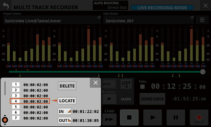
See “Editing takes” for details.
 (REW) button
When stopped, playing back or playback is paused, tap this button to start searching backward. Press and hold this button to search while it is being pressed.
Tap this button when searching backward to return to the state before searching backward.
When searching backward, this button will appear white.
 (F.FWD) button
When stopped, playing back or playback is paused, tap this button to start searching forward. Press and hold this button to search while it is being pressed.
Tap this button when searching forward to return to the state before searching forward.
When searching forward, this button will appear white.
 button
Tap this when recording/playing to stop recording/playing.
When stopped, this button will appear white.
Transport status indicator
This icon shows the MTR operation status.
|
Indicator appearance |
Operation status |
|
|
Stopped |
|
|
Playing |
|
|
Searching backward |
|
|
Searching forward |
|
|
Recording |
 button
Tap this when playback is stopped or paused to start playback.
Tap this when recording is paused to resume recording.
When recording or playing, this button will appear green.
When the MTR is stopped, tap this button to switch between routing for recording and routing for sound checks (MTR playback).
|
Button appearance |
Routing status |
|
|
Routing for recording |
|
|
Routing for playback |
NOTE
Recording is not possible when the SOUND CHECK button is on.
The MTR must be stopped to change the SOUND CHECK status. The following message will appear if changing the SOUND CHECK status is attempted while the MTR is operating.
|
To change, the MTR must be stopped. |
Tap this button to open a message that confirms switching the routing.
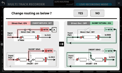
Example of confirmation message when turning on the SOUND CHECK button
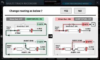
Example of confirmation message when turning off the SOUND CHECK button
Tapping the YES button on the confirmation message will switch the routing and button status.
Tapping the NO button will close the message without changing the routing or button status.
NOTE
The routing can be changed by turning the SOUND CHECK button on/off even if the lock/unlock setting for changing routing settings is locked on the MODULE (INPUT) Screen or INPUT SOURCE SELECT Screen, for example.
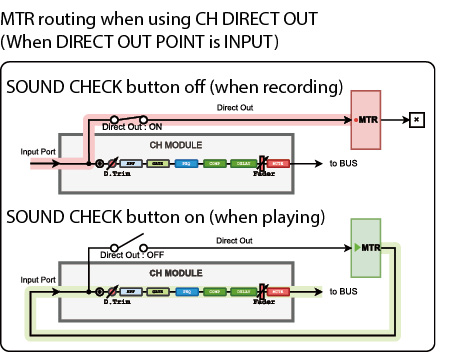
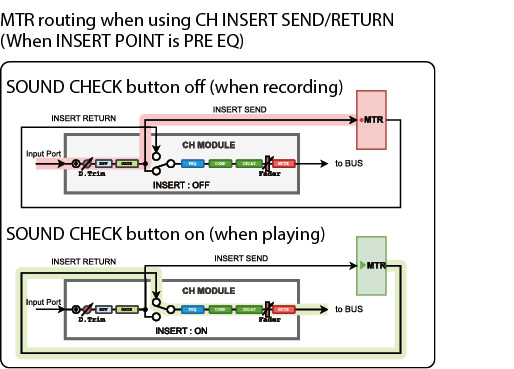
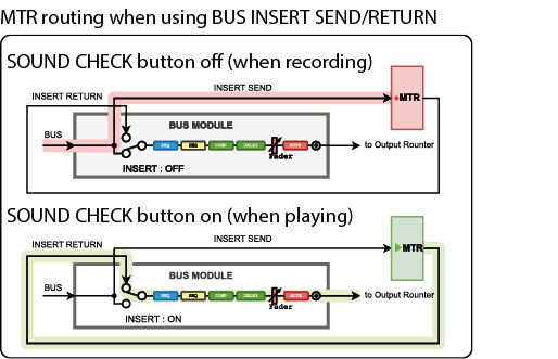
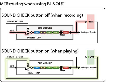
When recording the DIRECT OUT if the DIRECT OUT POINT setting is “POST HPF”*
Use caution because signals will pass through Phase/D.Trim/HPF again during sound check (playback) if Phase/D.Trim/HPF is enabled during recording.
When recording the DIRECT OUT if the DIRECT OUT POINT setting is “POST FADER”*
Use caution because signals will pass through Phase/D.Trim/HPF/GATE/EQ/COMP/DELAY again during sound check (playback) if Phase/D.Trim/HPF/GATE/EQ/COMP/DELAY is enabled during recording.
*Issues like the above will not occur when the DIRECT OUT POINT setting is “INPUT”.
When recording the BUS Output Port
Use caution because signals will pass through EQ/GEQ/COMP/DELAY/Phase again during sound check (playback) if EQ/GEQ/COMP/DELAY/Phase is enabled when recording the BUS Output Port.
To avoid two routes for processing the signals when recording and when playing back with the BUS module, set the routing from the BUS module to the MTR to “Insert Send”.
 button
Tap this when stopped or playing to pause playback.
When the MTR operation mode is LIVE RECORDING MODE or VIRTUAL SOUND CHECK MODE, tap when recording to pause recording.
This cannot be used during recording when the MTR operation mode is OVERDUB MODE.
When recording or playback is paused, this button will appear white.
 button
Tap this when stopped and at least one REC READY is on to put the unit into recording standby.
If the MTR operation mode is LIVE RECORDING MODE or VIRTUAL SOUND CHECK MODE, tapping this when recording will not interrupt recording, but will end the current take and start a new take (take splitting).
When the MTR operation mode is LIVE RECORDING MODE or VIRTUAL SOUND CHECK MODE, tap this when in recording standby to start a new take and remain in recording standby.
When the MTR operation mode is OVERDUB MODE and at least one REC READY is on, tap this when playing to punch in and start recording.
When recording or paused, this button will appear light red.
Time counter display mode
This shows the current time counter display mode.
Tap this area to switch the display mode.
|
Display mode |
Meaning |
|
TAKE |
This shows the elapsed time from the beginning of the take and the remaining time to the end of the take. |
|
PROJECT |
This shows the elapsed time from the beginning of the project and the remaining time to the end of the project. |
Elapsed time counter
This shows the elapsed recording/playback time in an hour: minute: second: 1/100 second format.
Tap the counter to switch to location time input mode and show number input and LOCATE buttons below it. Tap the LOCATE button to locate immediately to the input time.
Tap the button at the top right of the locate time input area to close it.
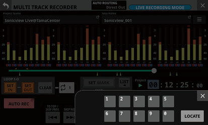
Remaining time counter
When the MTR operation mode is LIVE RECORDING MODE or VIRTUAL SOUND CHECK MODE
During playback, this shows the remaining time until the end of the take or project according to the selected display mode in an hour: minute: second: 1/100 second format.
When recording, this shows the remaining available recording time.
When the MTR operation mode is OVERDUB MODE
This shows the remaining available recording time.
AUTO PUNCH button/indicator
Tap this button to open the MULTI TRACK RECORDER - MENU Screen where settings for operation of the auto punch in/out function are made. (See “Automatic punch in/out function”.)
When on, this appears light red.
REHEARSAL button
Tap this button to turn the auto punch in/out rehearsal function on/off. (See “Rehearsing punching in and out”.)
This will blink when the rehearsal function is on.
This button can only be used when the automatic punch in/out function is on.
UNDO/REDO button
Tap this button when it appears lit to use the UNDO/REDO function. The UNDO button appears when UNDO is possible. The REDO button appears when UNDO has been used.
When this button appears unlit, UNDO and REDO are not possible.
![]() (TO TOP) button
(TO TOP) button
Tap this when stopped, playing or paused to return to the beginning of the take.
The button will appear white while it is being pressed.
![]() (TO END) button
(TO END) button
Tap this when stopped, playing or paused to skip to the end of the take.
The button will appear white while it is being pressed.
Using the AUTO ROUTING function
Tap the AUTO ROUTING () button at the top of the MULTI TRACK RECORDER Screen to use this function.
The AUTO ROUTING confirmation message below will be shown.
NOTE
AUTO ROUTING cannot be executed if the SOUND CHECK button is on (playback routing enabled). Turn the SOUND CHECK button off to enable the execution of AUTO ROUTING.
The routing can be changed with AUTO ROUTING even if the lock/unlock setting for changing routing settings is locked on the MODULE (INPUT) Screen and INPUT SOURCE SELECT Screen, for example.
When in LIVE RECORDING MODE
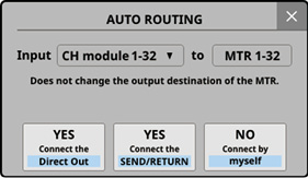
First, select “CH module 1–32” or “CH module 9–40”.
If the Sampling Rate (Max Tracks) button setting is “96kHz/16tracks” on the MULTI TRACK RECORDER - MENU Screen, select “CH module 1–16” or “CH module 25–40”.
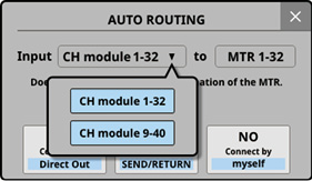
Tap the “YES Connect the Direct Out” button to route the DIRECT OUT connections of the selected CH module group to 1–32 of the slot with the IF-MTR32 installed.
If the Sampling Rate (Max Tracks) button setting is “96kHz/16tracks” on the MULTI TRACK RECORDER - MENU Screen, routing will be to 1–16 of the slot.
Tap the “YES Connect the SEND/RETURN” button to route the INSERT SEND/RETURN connections of the selected CH module group to 1–32 of the slot with the IF-MTR32 installed.
If the Sampling Rate (Max Tracks) button setting is “96kHz/16tracks” on the MULTI TRACK RECORDER - MENU Screen, routing will be to 1–16 of the slot.
In this case, the metering points of the CH module groups will be automatically switched according to the insert point settings as shown below.
|
Insert point setting for the selected CH module group |
CH module group metering point |
|
All PRE EQ |
PRE EQ |
|
All PRE FADER |
PRE FADER |
|
Mix of PRE EQ and PRE FADER |
PRE FADER |
Tapping the “NO Connect by myself” button will keep the current routing settings, so make necessary routing changes manually.
Tapping the ![]() button will close the message without changing routing settings.
button will close the message without changing routing settings.
When in VIRTUAL SOUND CHECK MODE
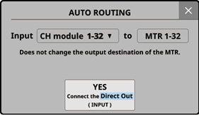
First, select “CH module 1–32” or “CH module 9–40”.
If the Sampling Rate (Max Tracks) button setting is “96kHz/16tracks” on the MULTI TRACK RECORDER - MENU Screen, select “CH module 1–16” or “CH module 25–40”.

Tap the “YES Connect the Direct Out (INPUT)” button to route DIRECT OUT connections that have DIRECT OUT POINT set to “INPUT” of the selected CH module group to 1–32 of the slot in which the IF-MTR32 is installed.
If the Sampling Rate (Max Tracks) button setting is “96kHz/16tracks” on the MULTI TRACK RECORDER - MENU Screen, routing will be to 1–16 of the slot.
Tapping the ![]() button will close the message without changing routing settings.
button will close the message without changing routing settings.
When in OVERDUB MODE
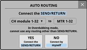
First, select “CH module 1–32” or “CH module 9–40”.
If the Sampling Rate (Max Tracks) button setting is “96kHz/16tracks” on the MULTI TRACK RECORDER - MENU Screen, select “CH module 1–16” or “CH module 25–40”.
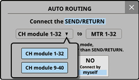
Tap the “YES Connect the SEND/RETURN” button to route the INSERT SEND/RETURN connections of the selected CH module group to 1–32 of the slot with the IF-MTR32 installed.
If the Sampling Rate (Max Tracks) button setting is “96kHz/16tracks” on the MULTI TRACK RECORDER - MENU Screen, routing will be to 1–16 of the slot.
In this case, the metering points of the CH module groups will be automatically switched according to the insert point settings as shown below.
|
Insert point setting for the selected CH module group |
CH module group metering point |
|
All PRE EQ |
PRE EQ |
|
All PRE FADER |
PRE FADER |
|
Mix of PRE EQ and PRE FADER |
PRE FADER |
Tapping the “NO Connect by myself” button will keep the current routing settings, so make necessary routing changes manually.
Tapping the ![]() button will close the message without changing routing settings.
button will close the message without changing routing settings.
NOTE
When the MTR operation mode is OVERDUB MODE, always use “Insert Send/Return” for routing between the mixer and the MTR.
Normal punch in/out recording will not be possible using different routing settings.
To switch between the three MTR operation modes, when the MTR is stopped, tap the MTR operation () button on the MULTI TRACK RECORDER Screen.
This will open the MTR operation mode switching menu.
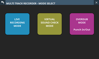
Tap one of the operation mode buttons to switch to that mode and open an AUTO ROUTING confirmation screen. (See “Using the AUTO ROUTING function”.)
Tap the ![]() button at the top left to return to the previous screen without changing the MTR operation mode.
button at the top left to return to the previous screen without changing the MTR operation mode.
NOTE
MTR must be stopped to change the MTR operation mode. The following message will appear if changing the MTR operation mode is attempted while the MTR is operating.
|
To change, the MTR must be stopped. |
SOUND CHECK must be “OFF” to change the MTR operation mode. The following message will appear if changing the MTR operation mode is attempted while SOUND CHECK is “ON”.
|
To change, SOUND CHECK must be OFF. |
At least one take is necessary to record in OVERDUB MODE. For this reason, if the current project has no takes, switching to OVERDUB MODE will cause the following message to be shown.
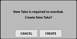
1.Tap the CREATE button to open the following confirmation message.
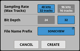
2.Set the Sampling Rate, Bit Depth and File Name Prefix.
3.Tap the CREATE button to create a take.
Tap the CANCEL button to open the MULTI TRACK RECORDER Screen without creating a take.
If the CANCEL button was tapped in any of the above confirmation messages
1.The following message will be shown when switching to the MULTI TRACK RECORDER Screen or if the MULTI TRACK RECORDER Screen button is tapped to start recording.
Tap the CREATE button to open the following confirmation message.
Set the Sampling Rate, Bit Depth and File Name Prefix, and tap the CREATE button to create a take and put the recorder in standby.
Tapping the CANCEL button on any of the above confirmation messages will restore it to a stopped state.
2.Tap the ![]() button at the top right of the take list on the BROWSE MTR Screen to open the following confirmation message.
button at the top right of the take list on the BROWSE MTR Screen to open the following confirmation message.
Set the Sampling Rate, Bit Depth and File Name Prefix, and tap the CREATE button to create a take.
Tap the CANCEL button to close the confirmation message without creating a take.
REC READY/INPUT MONITOR settings
Tap the MULTI TRACK RECORDER Screen meter/REC READY/INPUT MONITOR area () to open a REC READY / INPUT MONITOR settings window below the meters for the group of 8 tracks in the area tapped.
REC READY setting buttons are in the upper row and INPUT MONITOR setting buttons are in the lower row for the selected 8 tracks.
Tap these buttons to turn them on/off.
The REC READY setting buttons show the routing settings for the tracks as follows.
Top line: Track input signal
Bottom line: Track signal output destination
Tap the ![]() button at the top right of the REC READY / INPUT MONITOR settings window to close the window and restore the normal MULTI TRACK RECORDER Screen.
button at the top right of the REC READY / INPUT MONITOR settings window to close the window and restore the normal MULTI TRACK RECORDER Screen.
When INPUT MONITOR is on, the signal input to the MTR will be output from the MTR as is, regardless of the MTR operation status and REC READY on/off status.
When REC READY is on
When stopped or recording, sound input to the MTR will be output from the MTR as is.
During playback, the MTR playback sound is output from the MTR.
Tap the REC READY ALL ON/ALL OFF button to turn it on/off for all tracks.
The ALL ON and ALL OFF buttons show the REC READY setting status.
|
REC READY setting status |
ALL ON button appearance |
ALL OFF button appearance |
|
When all tracks are on |
|
|
|
When all tracks are off |
|
|
|
When some tracks are on and some are off |
|
|
Tap the INPUT MONITOR ALL ON/ALL OFF button to turn it on/off for all tracks.
The ALL ON and ALL OFF buttons show the INPUT MONITOR setting status.
|
INPUT MONITOR setting status |
ALL ON button appearance |
ALL OFF button appearance |
|
When all tracks are on |
|
|
|
When all tracks are off |
|
|
|
When some tracks are on and some are off |
|
|
MTR output according to REC READY and INPUT MONITOR settings
When in LIVE RECORDING MODE or VIRTUAL SOUND CHECK MODE
|
REC READY |
||||
|
|
|
|
|
|
|
INPUT MONITOR |
||||
|
|
|
|
|
|
|
When stopped |
No MTR output |
Sound input to the MTR is output from the MTR |
Sound input to the MTR is output from the MTR |
|
|
Playing/playback paused |
MTR playback sound is output from the MTR |
MTR playback sound is output from the MTR |
||
|
Recording/recording paused |
No MTR output |
Sound input to the MTR is output from the MTR |
||
When in OVERDUB MODE
|
REC READY |
||||
|
|
|
|
|
|
|
INPUT MONITOR |
||||
|
|
|
|
|
|
|
When stopped |
No MTR output |
Sound input to the MTR is output from the MTR |
Sound input to the MTR is output from the MTR |
|
|
Playing/playback paused |
MTR playback sound is output from the MTR |
MTR playback sound is output from the MTR |
||
|
Recording/recording paused |
MTR playback sound is output from the MTR |
Sound input to the MTR is output from the MTR |
||
Yellow cells: Setting combinations that have different results in LIVE RECORDING MODE / VIRTUAL SOUND CHECK MODE and in OVERDUB MODE
MULTI TRACK RECORDER - MENU Screen
Use this screen to make various settings for the IF-MTR32 (multitrack recorder) card installed in SLOT 1 or SLOT 2.
To open this screen, tap Menu Screen > Recorder/Player menu > Multi Track Recorder to open the MULTI TRACK RECORDER Screen. Then, tap the ![]() button at the top right when the MTR is stopped.
button at the top right when the MTR is stopped.
MTR - MENU Screen when in LIVE RECORDING MODE
.jpg)
MTR - MENU Screen when in OVERDUB MODE
.jpg)
BROWSE button
Tap this button to open the BROWSE MTR Screen. (See “MULTI TRACK RECORDER - BROWSE Screen”.)
Sampling Rate (Max Tracks) buttons
This sets the sampling frequency and maximum number of tracks when the MTR operation mode is LIVE RECORDING MODE or VIRTUAL SOUND CHECK MODE.
The selected button will be highlighted light blue.
Options: 48 kHz / 32 tracks (default), 96 kHz / 16 tracks
NOTE
The sampling frequency for the IF-MTR32 can be set to a value different from the Sync Clock of the Sonicview 16XP/24XP that it is installed in.
Since the number of tracks that can be recorded/played changes when this setting is switched, a routing change confirmation message will appear as shown below.
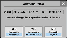
Message when switching to 48 kHz / 32 tracks
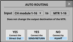
Message when switching to 96 kHz / 16 tracks
Bit Depth buttons
This setting will be used for the bit depth when the MTR operation mode is LIVE RECORDING MODE or VIRTUAL SOUND CHECK MODE.
The selected button will be highlighted light blue.
Options: 24-bit, 32-bit (default)
File Name Prefix buttons
This setting will be used for the first characters of recording file names when the MTR operation mode is LIVE RECORDING MODE or VIRTUAL SOUND CHECK MODE.
The selected button will be highlighted light blue.
|
Option |
Meaning |
|
DATE (default) |
The year, month and day that the recording started will be added to the recording file name in YYMMDD format. |
|
Edit Name |
The file name set by the user will be used as the recording file name (SONICVIEW by default). The set name is shown on the button. Tap the EDIT button on the right to open the Edit Name Screen where the file name set by the user can be edited. |
Media status
This shows the status of the SD card loaded in the IF-MTR32.
|
Item |
Explanation |
|
UHS-I |
This area will appear lit if the card supports UHS-I. |
|
Capacity |
Shows the total amount of space on the SD card. |
|
Free |
This shows the amount of unused capacity on the SD card. |
Use these to format the SD card loaded in the IF-MTR32.
We recommend using the ERASE option to format SD cards when using them with the IF-MTR32 for the first time.
Tap the QUICK button to format only the application management area on the medium.
Tap the ERASE button to conduct erase formatting.
ATTENTION
Formatting will erase all the data on the SD card. Back up to a computer, for example, before formatting a card.
NOTE
ERASE formatting takes more time than QUICK formatting. We recommend doing this when plenty of time is available.
The writing speeds to SD cards and other storage media that use flash memory tend to decrease after writing occurs repeatedly. If the writing speed decreases, this could have a negative impact on recording.
Using the ERASE formatting function of this unit should restore the writing speed of the SD card.*
For this reason, we recommend using the ERASE formatting function at the following times.
If the following message appears when recording
|
MTR Recording Error. Buffer overflow. |
Whenever the card has been written to until it became completely full
On a regular schedule (about once per month)
Before starting important recordings
*Writing speed might not be restored depending on the SD card condition (including malfunction and age).
AUTO REC button
Tap this button to turn the automatic recording function on/off (default).
When on, this button will appear red.
See “Automatic recording function” for details.
Automatic recording function setting knobs
Use these to set the automatic recording operation levels and time.
Start Level knob
This sets the level for starting automatic recording.
Use LCD knob 6, which is lit red, to set this. (See “Automatic recording function”.)
Options: OFF*, −72 dBFS – −24 dBFS (in 6 dBFS increments, −42 dBFS default)
*When “OFF” is selected, tap the button on the MULTI TRACK RECORDER Screen to start recording.
End Level knob
This sets the level for ending automatic recording.
Use LCD knob 7, which is lit yellow, to adjust it. (See “Automatic recording function”.)
Options: OFF*, −72 dBFS – −24 dBFS (in 6 dBFS increments, −42 dBFS default)
*When “OFF” is selected, tap the button on the MULTI TRACK RECORDER Screen to stop recording.
End Time knob
This sets the time until automatic recording stops after the recording level goes below the End Level.
Use LCD knob 8, which is lit green, to adjust it. (See “Automatic recording function”.)
If the recording level goes above the End Level before this time elapses, recording will continue.
Range: 1 – 60 seconds (default: 5 seconds)
End Mode buttons
Tap one of these buttons to set what happens when automatic recording has started and the End Time has elapsed after the recording level has gone below the End Level. (See “Automatic recording function”.)
|
Option |
Meaning |
|
Take Split (default) |
Standby for recording in a new file |
|
Continue |
Standby for recording in the same file |
The selected button will be highlighted light blue.
PRE REC button
Tap this button to turn the pre-recording function on/off. (default: OFF)
When on, this button will appear red.
See “Pre-recording function” for details.
Version button
Tap this button to open a window that shows information about the IF-MTR32 firmware version.
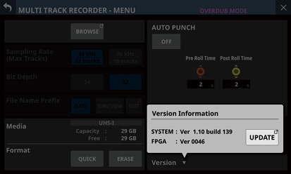
Tap the UPDATE button to open the Firmware Update Screen for the slot with the IF-MTR32 installed.
AUTO PUNCH button
Tap this button to turn the auto punch in/out function ON/OFF (default).
When on, this button will appear red.
See “Automatic punch in/out function” for details.
Auto punch in/out function setting knobs
Use these to set the auto punch in/out function operation times. (See “Automatic punch in/out function”.)
Pre Roll Time knob
This sets the pre-roll time for the auto punch in.
Use LCD knob 6, which is lit red, to set this.
Range: 0 – 10 seconds (default: 2 seconds)
Post Roll Time knob
This sets the post roll time for the auto punch out.
Use LCD knob 7, which is lit yellow, to adjust it.
Range: 0 – 10 seconds (default: 2 seconds)
MULTI TRACK RECORDER - BROWSE Screen
Use this screen to select folders and files on the SD card loaded in the IF-MTR32 (multitrack recorder) card installed in SLOT 1 or SLOT 2.
To open this screen, tap Menu Screen > Recorder/Player menu > Multi Track Recorder to open the MULTI TRACK RECORDER Screen. Then, tap the project/take name. This screen can also be opened by tapping the BROWSE button on the MULTI TRACK RECORDER - MENU Screen.
BROWSE MTR Screen showing project list
.jpg)
BROWSE MTR Screen showing take list
.jpg)
Level name
This shows the icon and name of the level that is currently open.
“MTR Projects Root” will be shown when the project list is open.
The name of the project that contains the takes will be shown when the take list is open. When the current project is being shown, “(current project)” will appear after the name.
![]() button
button
Use this button to create a new project folder at the root level of the SD card.
Tap this button to open a screen where the name of the folder being created can be input.
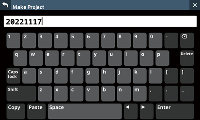
The combination of characters input can be changed depending on the status of the Caps lock and Shift keyboard buttons on the Make Project Screen.
See “Changing the keyboard keys” for details about changing the keyboard.
Project list
This shows the names of project folders on the root level of the SD card in name order.
Tap a project in this area to select it as the current project.
A check (![]() ) is shown next to the name of the current project.
) is shown next to the name of the current project.
Project menu buttons (![]() )
)
Tap one of these buttons to open a menu window that enables the following operations on the project folder shown to the left.
|
Menu item |
Explanation |
|
Open |
This selects the project folder to the left of the tapped |
|
Rename |
This opens a screen where the name of the project folder to the left of the tapped |
|
Delete |
This deletes the project folder to the left of the tapped |
NOTE
This operation is not possible during recording and playback.
Rename and Delete cannot be used with the current project.
Scrollbar
This appears when the number of folders and files exceeds the amount that can be shown on the display at the same time.
Drag the scrollbar to scroll the screen. The project/take list can also be scrolled by swiping it up and down as well as by turning LCD knob 8.
Level change button
Tap the ![]() button to show the folder level one step above the current level.
button to show the folder level one step above the current level.
NOTE
This will be gray when the MTR Projects Root (highest) level is open.
Take list
This shows the names and lengths of the takes in the project folder that is currently being shown. Tap this area to select a take as the current take, adding a check mark (![]() ) to it.
) to it.
Take menu buttons (![]() )
)
Tap one of these buttons to open a menu window that enables the following operations on the take shown to the left.
|
Menu item |
Explanation |
|
Open |
This selects the take to the left of the tapped |
|
Rename |
This opens a screen where the name of the take to the left of the |
|
Delete |
This deletes the take to the left of the |
NOTE
This operation is not possible during recording and playback.
New take creation button (OVERDUB MODE only)
Use this button to create a new take.
Tap this button to open the following confirmation message.
Set the Sampling Rate, Bit Depth and File Name Prefix, and tap the CREATE button to create a take.
The IF-MTR32 manages audio files in project folders.
The SD card contains “PROJECT” and other project folders. These project folders contain audio files called takes (files from single recordings).
The illustration below shows the folder structure.
The folder and file structure can be checked by accessing the SD card using a computer with an SD card reader.
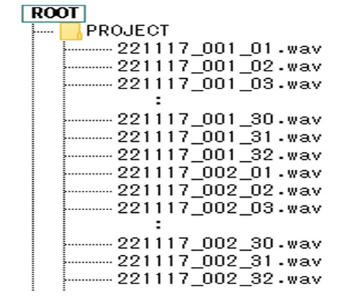
NOTE
Other folders and files will also be created for management.
Only folders at the root of the SD card can be selected as the current folder. Folders in other locations cannot be selected as the current folder.
The naming pattern for recording files is as follows.
[1–9-character File Name Prefix]_[3-digit take number]_[2-digit track number].wav
The IF-MTR32 can record and play files with the following formats.
File format: BWF/WAV*
Sampling frequency: 48 kHz, 96 kHz
Quantization bit depth: 16-bit**, 24-bit, 32-bit
Number of channels: 1 (mono)
*This unit does not record files in WAV format, but it can play them.
** Recording with a quantization bit depth of 16-bit is not possible. Moreover, punching in/out is not possible with takes that contain 16-bit tracks. For this reason, selecting takes that contain 16-bit tracks is not possible when the MTR operation modes is OVERDUB MODE.
NOTE
The single-channel WAV files named “[File Name Prefix]_[2-digit track number].wav” and numbered 32 and below when the sampling frequency is 48 kHz (16 and below when the sampling frequency is 96 kHz) are recognized as a single take.
Single-digit track numbers have “0” placed at the number beginnings, for example “01” and “02”.
WAV files with the following “[2-digit track number]” values in their names are recognized as individual takes.
48kHz sampling frequency: 33 and higher
96kHz sampling frequency: 17 and higher
WAV files without “[2-digit track number]” values in their names are recognized as individual takes.
With the IF-MTR32 (multi track recording) card, groups of files recorded at the same time are called “takes”. The folders that contain recorded takes are handled as “projects” and data is managed separately for each project folder.
To record and produce music, a project folder that has already been created must be selected or a new project folder must be created.
This chapter describes functions that range from basic operations such as procedures for selecting and creating new projects to various project management functions.
NOTE
To use the WAV files from a project in a DAW or other application, copy them to a computer. Do not use the files on the SD card directly.
Viewing project and take lists
To open a list of projects/takes saved on the SD card, tap the project or take name area on the MULTI TRACK RECORDER screen to open the BROWSE MTR Screen. The BROWSE MTR screen can also be opened by tapping the BROWSE button on the MULTI TRACK RECORDER - MENU Screen. (See “MULTI TRACK RECORDER - BROWSE Screen”.)
Tap the ![]() button at the right end of a project folder name on the BROWSE MTR Screen to open a menu window where project operations can be conducted.
button at the right end of a project folder name on the BROWSE MTR Screen to open a menu window where project operations can be conducted.
Tap the buttons in the menu window to conduct project operations.
|
Menu item |
Explanation |
|
Open |
Tapping this selects that project as the current project and opens its take list. |
|
Rename |
Tapping this opens the Rename screen where the name of the selected project can be changed. |
|
Delete |
Tap this to open a message confirming whether or not to delete the selected project.
|
NOTE
This operation is not possible during recording and playback.
Rename and Delete cannot be used with the current project.
To record or play with this unit, you must create and select a project.
The following procedure can be used to create a new project.
1.Open the BROWSE MTR Screen when the MTR is stopped. (See “MULTI TRACK RECORDER - BROWSE Screen”.)
2.Tap the ![]() button at the top right of the screen to open the Make Project Screen where the name of the project being created can be input.
button at the top right of the screen to open the Make Project Screen where the name of the project being created can be input.
3.The combination of characters input can be changed depending on the status of the Caps lock and Shift keyboard buttons on the Make Project Screen. See “Changing the keyboard keys” for details about changing the keyboard.
TIP
The project name can be changed later on the Rename Screen.
4.Tap the Enter button to create a new project and return to the BROWSE MTR Screen.
NOTE
To cancel project creation, tap the ![]() button at the top left of the screen.
button at the top left of the screen.
Input project names must be at least 1 character and no more than 11 characters.
Project are created on the root level of the SD card.
If a folder with the same name already exists when the Enter button is tapped, the following message will appear. Input a different name.
|
This name already exists. Please enter another name. |
Follow the procedures below to select the project to use.
1.Open the BROWSE MTR Screen when the MTR is stopped.(See “MULTI TRACK RECORDER - BROWSE Screen”.)
NOTE
A check (![]() ) is shown next to the name of the project that is currently selected.
) is shown next to the name of the project that is currently selected.
2.Tap the name of a project folder to select it as the current project, adding a check (![]() ) next to the name.
) next to the name.
NOTE
The following selection procedures can also be used.
1. Tap the ![]() button at the right end of a project folder name to open a menu window.
button at the right end of a project folder name to open a menu window.
2. Tap the Open button to set the selected project as the current project and open its take list.
Projects can be deleted.
Deleting unnecessary projects when the SD card space is low can create more open space.
NOTE
The current project cannot be deleted.
Files might be saved on the SD card for using the UNDO function in OVERDUB MODE. Those files can be deleted if the SD card loaded in the IF-MTR32 is removed and reinserted.
1.Open the BROWSE MTR Screen when the MTR is stopped. (See “MULTI TRACK RECORDER - BROWSE Screen”.)
2.Tap the ![]() button at the right end of the folder name of the project that you want to delete to open a menu window.
button at the right end of the folder name of the project that you want to delete to open a menu window.
3.Tap the Delete button to open a message confirming whether or not to delete the selected project.
Tap the CANCEL button to close the confirmation message.
Tapping the OK button will delete the selected project and close the confirmation message.
1.Open the BROWSE MTR Screen when the MTR is stopped. (See “MULTI TRACK RECORDER - BROWSE Screen”.)
2.Tap the ![]() button at the right end of the folder name of the project that you want to rename to open a menu window.
button at the right end of the folder name of the project that you want to rename to open a menu window.
3.Tap the Rename button to open the Rename Screen where the name of the selected project can be changed.
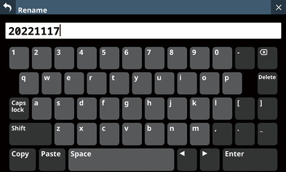
4.Change the project name.
The combination of characters input can be changed depending on the status of the Caps lock and Shift keyboard buttons on the Rename Screen. See “Changing the keyboard keys” for details about changing the keyboard.
5.Tap the Enter button to change the project name and return to the BROWSE MTR Screen.
NOTE
To cancel project renaming, tap the ![]() button at the top left of the screen.
button at the top left of the screen.
Changed project names must be at least 1 character and no more than 11 characters.
The name of the current project cannot be changed.
If a folder with the same name already exists when the Enter button is tapped, the following message will appear. Input a different name.
|
This name already exists. Please enter another name. |
Selecting the MTR input source
The input source can be selected for the IF-MTR32 (multitrack recording) card.
MTR and automatic routing
Tap the AUTO ROUTING () button at the top of the MULTI TRACK RECORDER Screen to open the following routing confirmation message.
After selecting either “CH module 1-32” or “CH module 9-40”, tap the “YES Connect the Direct Out” button to route the DIRECT OUT connections of the selected CH module group to 1–32 of the slot in which the IF-MTR32 is installed.
Tap the “YES Connect the SEND/RETURN” button to route the INSERT SEND/RETURN connections of the selected CH module group to 1–32 of the slot in which the IF-MTR32 is installed.
Tapping the “NO Connect by myself” button will keep the current routing settings, so make necessary routing changes manually.
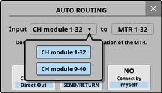
Tap the ![]() button to close the message. Doing this will retain the current routing settings.
button to close the message. Doing this will retain the current routing settings.
Manual input routing to the MTR
Audio signals can be input to the MTR by assigning the desired signals to the output ports of the SLOT that the IF-MTR32 is installed in.
To send the audio signal of a CH module to the MTR, select “1-32” of the slot in which the IF-MTR32 is installed for the following assignment destinations.
DIRECT OUT (DIRECT OUT button on)
Insert Send
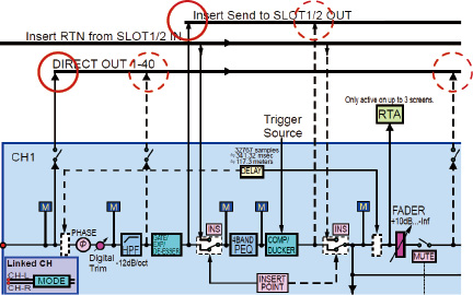
To send the audio signal of a BUS module to the MTR, select “1-32” of the slot in which the IF-MTR32 is installed for the following assignment destinations.
Insert Send
Output Port
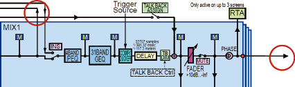
NOTE
Input port audio signals cannot be sent to the MTR without assigning them to a CH module.
Precautions
When recording the DIRECT OUT if the DIRECT OUT POINT setting is “POST HPF”:
Use caution because signals will pass through Phase/D.Trim/HPF again during sound check (playback) if Phase/D.Trim/HPF is enabled during recording.
When recording the DIRECT OUT if the DIRECT OUT POINT setting is “POST FADER”:
Use caution because signals will pass through Phase, D.Trim, HPF, GATE, EQ, COMP and DELAY again during sound check (playback) if they are enabled during recording.
How to avoid these issues
To avoid two routes for processing the signals when recording and when playing back with the CH module, set the routing from the CH module to the MTR to one of the following.
DIRECT OUT with DIRECT OUT POINT setting set to “INPUT”
Insert Send
Precaution
When recording the BUS Output Port:
Use caution because signals will pass through EQ/GEQ/COMP/DELAY/Phase again during sound check (playback) if EQ/GEQ/COMP/DELAY/Phase is enabled when recording the BUS Output Port.
How to avoid this issue
To avoid two routes for processing the signals when recording and when playing back with the BUS module, set the routing from the BUS module to the MTR to “Insert Send”.
This unit can simultaneously record up to 32 tracks.
The following recording procedures are an example of steps to take when recording with the IF-MTR32 for the first time.
1.Load an SD card in the IF-MTR32.
2.Use the Erase Format function on the MULTI TRACK RECORDER - MENU Screen to format the SD card. (See “ Format buttons”.)
3.Tap the MTR operation mode button at the top of the MULTI TRACK RECORDER Screen (See “ MTR operation mode button”.), and select LIVE RECORDING MODE or VIRTUAL SOUND CHECK MODE.
4.Set REC READY to “On” for the tracks to record.
Recording standby will be enabled, and the REC READY indicators will blink red.
5.Adjust the input levels of each channel that will be recorded.
6.Tap the button on the MULTI TRACK RECORDER Screen to pause recording.
7.Tapping the button on the MULTI TRACK RECORDER Screen will start recording and make the and buttons appear lit.
The REC READY indicators for tracks being recorded will stop blinking and stay lit.
8.When recording has completed, tap the button.
Checking recorded audio (playing recordings)
1.Switch to MTR routing for playback.
Tap the SOUND CHECK button on the MULTI TRACK RECORDER Screen and confirm the message that is shown (See “ SOUND CHECK button”.). This highlights the button and routes the MTR outputs to the recording channel inputs and Insert Return, enabling playback monitoring.
See “ SOUND CHECK button” for details switching MTR routing.
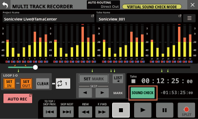
2.Use the / and buttons on the MULTI TRACK RECORDER Screen, for example, to locate to a position you want to check.
NOTE
For details about the locate function, see “Locate function”.
3.Tap the button on the MULTI TRACK RECORDER Screen to play the recorded tracks.
NOTE
To replace parts of tracks, switch the MTR operation mode to OVERDUB MODE and punch in/out. (See “Punch in/out function” and “Automatic punch in/out function”.)
The playback position can be moved on the MULTI TRACK RECORDER Screen in the following ways.
All these methods can be used when the recorder is stopped or playing back.
Drag the progress bar left or right
This allows approximate changes to the location to be made quickly.
Turn LCD knob 8 (lit green) when the MULTI TRACK RECORDER Screen is open
Each click of LCD knob 8 changes the playback position by 50–70 ms. Each click of LCD knob 8 while it is being pressed changes the playback position by about 10 sec.
Press and hold the or button
Input the location time
Inputting the location time to locate
The current position of the recorder can be moved by inputting the time in the time counter.
1.Tap the elapsed time counter on the MULTI TRACK RECORDER Screen to switch to location time input mode and show number input and LOCATE buttons below the time counter.
2.Input the desired location time.
3.Tap the LOCATE button to locate (move) immediately to the input time.
The repeat playback function can be used to play something over and over.
Tap the repeat mode setting button on the MULTI TRACK RECORDER Screen to set the repeat playback function.
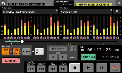
When the MTR operation mode is LIVE RECORDING MODE or VIRTUAL SOUND CHECK MODE, tap the repeat mode setting button to cycle through these options: OFF, 1, ALL and I-O.
When the MTR operation mode is OVERDUB MODE, tap the repeat mode setting button to cycle through these options: OFF, 1, and I-O. Repeat playback is not possible, however, when the AUTO PUNCH setting is “ON”.
|
Repeat mode |
Function |
|
|
Playback will not be repeated. |
|
|
The entire take that is currently selected will be played repeatedly. |
|
|
The entire project will be played repeatedly. This can be selected when the MTR operation mode is LIVE RECORDING MODE or VIRTUAL SOUND CHECK MODE. |
|
|
Playback will be repeated between the IN and OUT points. (See “Setting the punch in/out points”.) |
NOTE
If the MTR operation mode is switched to OVERDUB MODE when the repeat mode is set to ALL, the repeat mode will be automatically switched to OFF.
This function can start recording automatically.
Recording starts automatically when the recording level exceeds a set level. In addition, the recorder can be set to pause the current file or start a new file when the recording level goes below a set level.
Make these settings on the MULTI TRACK RECORDER - MENU Screen.
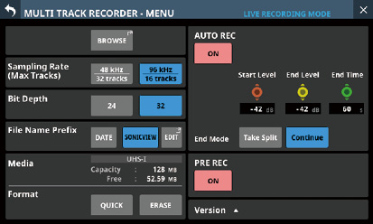
NOTE
This can be used when the MTR operation mode is LIVE RECORDING MODE or VIRTUAL SOUND CHECK MODE.
AUTO REC button
Tap this button to turn the automatic recording function on/off (default).
When On, this button will appear red and recording will occur according to the following settings.
Start Level knob
This sets the level for starting automatic recording.
Use LCD knob 6, which is lit red, to set this.
Options: OFF*, −72 dBFS – −24 dBFS (in 6 dBFS increments, −42 dBFS default)
*When “OFF” is selected, tap the button on the MULTI TRACK RECORDER Screen to start recording.
End Level knob
This sets the level for ending automatic recording.
Use LCD knob 7, which is lit yellow, to adjust it.
Options: OFF*, −72 dBFS – −24 dBFS (in 6 dBFS increments, −42 dBFS default)
*When “OFF” is selected, tap the button on the MULTI TRACK RECORDER Screen to stop recording.
End Time knob
This sets the time until automatic recording stops after the recording level goes below the end level.
Use LCD knob 8, which is lit green, to adjust it.
If the recording level goes above the End Level before this time elapses, recording will continue.
Range: 1 – 60 seconds (default: 5 seconds)
End Mode buttons
Tap one of these buttons to set what happens when automatic recording has started and the End Time has elapsed after the recording level has gone below the End Level.
|
Option |
Meaning |
|
Take Split (default) |
Standby for recording in a new take |
|
Continue |
Standby for recording in the same take |
The selected button will be highlighted light blue.
When recording is paused, this function can record up to two seconds of signal input before recording is started.
Make these settings on the MULTI TRACK RECORDER - MENU Screen.
NOTE
This can be used when the MTR operation mode is LIVE RECORDING MODE or VIRTUAL SOUND CHECK MODE.
PRE REC button
Tap this button to turn the pre-recording function on/off. (default: OFF)
When on, this button will appear red.
Punching in and out is a function used to replace parts of already recorded tracks.
After starting playback of the recorder, use this to switch to recording when it reaches the part to be replaced (punch in). Then, switch back to playback when the end of that part is reached (punch out) and stop after the set amount of time.
NOTE
This can only be used when the MTR operation mode is OVERDUB MODE.
When the MTR operation mode is OVERDUB MODE, always use Insert Send/Return for mixer and MTR routing. Normal punch in/out recording will not be possible using different routing settings.
1.Determine the part you want to replace in advance.
Select a point where the replacement audio can be combined well with the original track audio.
2.Turn on REC READY for the track with the part to be replaced and enter recording standby (REC READY indicator blinks red).
3.Start playback before the part to be replaced.
4.When the part to be replaced is reached, tap the button on the MULTI TRACK RECORDER Screen, and perform the part.
Recording will start (punch in).
5.When the end of the part to be replaced is reached, tap the or button on the MULTI TRACK RECORDER Screen.
Tap the button to stop recording.
Tap the button to switch from recording to playback.
Using the footswitch to punch in/out
A footswitch can be used to punch in/out if the recommended TASCAM RC-1F footswitch (sold separately) is connected to the FOOTSWITCH jack on the rear panel.
To use a footswitch to punch in/out, you must set the foot switch function assignment to “Punch IN/OUT” for "MTR" in advance. (See “Foot Switch page”.)
At step 4 above, press the footswitch instead of the button, and at step 5 press it again instead of the button.
NOTE
This unit was designed to be used with unlatched (momentary) footswitches that have to be pushed to function (shorted when pushed).
Automatic punch in/out function
Using the automatic punch in/out function, you can automatically record between punch in and out points set in advance.
To use the automatic punch in/out functions, start playback from a pre-roll point before the punch in point where recording will start.
Recording will stop when the punch out point is reached, and playback will stop after the post roll.
NOTE
This can only be used when the MTR operation mode is OVERDUB MODE.
Setting the punch in/out points
1.Open the MULTI TRACK RECORDER Screen.
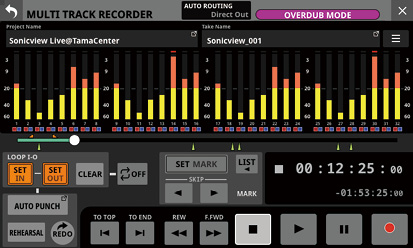
2.Tap the button to start playback.
3.Tap the SET IN button at the punch in point and the SET OUT button at the punch out point.
The set points are shown above the progress bar as ![]() and
and ![]() .
.
NOTE
Punch in/out points can also be set when stopped.
Set the in and out points at least 200 ms apart. If the interval is less than 200 ms, the following message will appear and the later point will not be set.
|
Invalid I/O. Interval too short. |
Trying to set the out point before the in point or the in point after the out point will fail and the following message will appear. Set the in point so that it is before the out point.
|
Invalid I/O. Please set IN and OUT in order. |
Tap the CLEAR button to clear set punch in and out points.
4.Press the button to stop playback.
5.Tap the AUTO PUNCH button to open the MULTI TRACK RECORDER - MENU Screen and turn on the automatic punch in/out function.
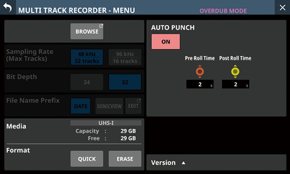
6.Tap the ![]() button at the top left of the screen to return to the MULTI TRACK RECORDER Screen.
button at the top left of the screen to return to the MULTI TRACK RECORDER Screen.
NOTE
By setting only the punch in point, you can start recording with automatic punch in and then continue recording until you tap the or button to stop.
By setting only the punch out point, you can start recording by tapping the button and then stop recording with automatic punch out.
Setting pre roll and post roll points
When using automatic punch in/out, set the amount of playback time before the punch in point (pre roll point) and the amount after the punch out point before playback stops (post-roll point).
1.Open the MULTI TRACK RECORDER - MENU Screen when the MTR is stopped. (See “MULTI TRACK RECORDER - MENU Screen”.)
2.Use LCD knob 6, which is lit red, to adjust the Pre Roll Time, and use LCD knob 7, which is lit yellow, to adjust the Post Roll Time.
Pre Roll Time: 0 – 10 seconds (default: 2 seconds)
Post Roll Time: 0 – 10 seconds (default: 2 seconds)
3.Tap the ![]() button at the top left of the screen to return to the MULTI TRACK RECORDER Screen.
button at the top left of the screen to return to the MULTI TRACK RECORDER Screen.
Rehearsing punching in and out
You can rehearse before punch in/out recording. In rehearsal, recording will not occur, but monitoring will be the same as if recording.
1.Confirm that the AUTO PUNCH button appears red on the MULTI TRACK RECORDER Screen.
2.Tap the REHEARSAL button on the MULTI TRACK RECORDER Screen to turn it on, highlighting it.
3.Turn on REC READY for the tracks to use with automatic punch in/out. (See “REC READY/INPUT MONITOR settings”.)
4.Tap the button.
Auto punch in/out rehearsal starts.
The transport starts playback from the pre-roll point. Both track playback and input source signals can be monitored. (See “Setting pre roll and post roll points”.)
When the punch in point is reached, only the input source signal will be monitored. The button will blink, showing that it rehearsal mode is active.
When the punch out point is reached, both track playback and input source signals will be monitored. The button will become gray.
When the set Post Roll Time has elapsed after the punch out point, playback will automatically stop and the button will blink. (See “Setting pre roll and post roll points”.)
Rehearsal can be repeated.
Using automatic punching in and out
Follow these procedures to punch in and out automatically and record.
1.Confirm that the AUTO PUNCH button appears red on the MULTI TRACK RECORDER Screen.
2.Tap the REHEARSAL button on the MULTI TRACK RECORDER Screen to turn it off, making it appear gray.
3.Turn on REC READY for the tracks to use with automatic punch in/out. (See “REC READY/INPUT MONITOR settings”.)
4.Tap the button.
The transport starts playback from the pre-roll point. Both track playback and input source signals can be monitored. (See “Setting pre roll and post roll points”.)
When the punch in point is reached, only the input source signal will be monitored, and the button will appear lit.
When the punch out point is reached, both track playback and input source signals will be monitored. The button will become gray.
When the set Post Roll Time has elapsed after the punch out point, playback will automatically stop and the button will blink. (See “Setting pre roll and post roll points”.)
NOTE
The following message will appear if the button is tapped when the AUTO PUNCH button is lit red but the punch in and out points have not been set.
Tap the button after setting the punch in and out points.
|
Cannot execute AUTO PUNCH. Set both I/O points. |
The following message will appear if the button is tapped during MTR playback when the AUTO PUNCH button is lit red.
Tap the button after stopping the MTR.
|
Cannot execute AUTO PUNCH. Stop the MTR. |
Undoing auto punch in/out operations (UNDO function)
If you want to redo punching in and out, the operation last conducted can be undone.
When a project is loaded or the unit is turned off, information about previous operations will be lost, so undoing and redoing them will no longer be possible.
NOTE
Files used for undoing are sometimes saved on the SD card. Those files can be deleted if the SD card loaded in the IF-MTR32 is removed and reinserted.
Undoing the most recent punch in/out operation
Tap the UNDO button on the MULTI TRACK RECORDER Screen to start undoing and open a message.
When undoing completes, the state before the previous operation will be restored and the message will close.
Redoing an undone operation
After undoing, tap the REDO button on the MULTI TRACK RECORDER Screen to start redoing and open a message.
When redoing completes, the state before undoing will be restored and the message will close.
1.Open the BROWSE MTR Screen when the MTR is stopped. (See “MULTI TRACK RECORDER - BROWSE Screen”.)
2.Tap the ![]() button at the right of the take name that you want to rename to open a menu window.
button at the right of the take name that you want to rename to open a menu window.
3.Tap the Rename button to open the Rename Screen where the name of the selected take can be changed.
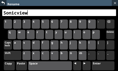
4.Change the take name.
The combination of characters input can be changed depending on the status of the Caps lock and Shift keyboard buttons on the Rename Screen. See “Changing the keyboard keys” for details about changing the keyboard.
5.Tap the Enter button to change the take name and return to the BROWSE MTR Screen.
NOTE
Changed take names must be at least 1 character and no more than 16 characters.
To cancel take renaming, tap the ![]() button at the top left of the screen.
button at the top left of the screen.
If a take with the same name already exists in the same folder when the Enter button is tapped, the following message will appear. Input a different name.
|
This name already exists. Please enter another name. |
Specified takes can be deleted.
Deleting unnecessary takes when the SD card space is low can create more open space.
NOTE
Files might be saved on the SD card for using the UNDO function in OVERDUB MODE. Those files can be deleted if the SD card loaded in the IF-MTR32 is removed and reinserted.
1.Open the BROWSE MTR Screen when the MTR is stopped. (See “MULTI TRACK RECORDER - BROWSE Screen”.)
2.Tap the ![]() button at the right of the take that you want to delete to open a menu window.
button at the right of the take that you want to delete to open a menu window.
3.Tap the DELETE button to open a message confirming whether or not to delete the selected take.
Tap the CANCEL button to close the confirmation message.
Tapping the OK button will delete the selected take and close the confirmation message.
Importing files that have been recorded on other devices
Audio files that meet the following conditions can be imported and played as takes. Moreover, files that were created on an IF-MTR32 (multitrack recording) card and meet the following conditions can be played as is.
File format: BWF/WAV
Sampling frequency: 48 kHz, 96 kHz
Quantization bit depth: 16-bit, 24-bit, 32-bit
Number of channels: 1
[File name first half]_[2-digit track number].wav
Examples:
SONICVIEW_001_01.wav (track 1 file)
SONICVIEW_001_02.wav (track 2 file)
:
SONICVIEW_001_31.wav (track 31 file)
SONICVIEW_001_32.wav (track 32 file)
ATTENTION
Punching in/out is not possible with takes that contain 16-bit tracks. For this reason, selecting takes that contain 16-bit tracks is not possible in OVERDUB MODE.
NOTE
WAV files named “[File name first half]_[2-digit track number].wav” with 2-digit track numbers from “01” to “32” when the sampling frequency is 48 kHz (“01” to “16” when the sampling frequency is 96 kHz) are recognized as a single take.
Single-digit track numbers have “0” placed at the number beginnings, for example “01” and “02”.
WAV files with the following “[2-digit track number]” values in their names are recognized as individual takes.
48kHz sampling frequency: 33 and higher
96kHz sampling frequency: 17 and higher
WAV files without “[2-digit track number]” values in their names are recognized as individual takes.
Always use an IF-MTR32 to format SD cards before using them with an IF-MTR32 for the first time. SD cards formatted by an IF-MTR32 are optimized for improved performance.
Operation of this unit might be affected when using an SD card that has been formatted by a computer or other device.
1.Use the IF-MTR32 to format the SD card. (See “ Format buttons”.)
NOTE
When formatted by an IF-MTR32, a “PROJECT” folder will automatically be created at the root level.
2.Remove the formatted SD card and load it in an SD card reader connected to a computer.
3.When a card has been formatted by an IF-MTR32, the computer will recognize it as a drive named “IF-MTR32”.
4.Copy the audio files that you want to load to a folder on the “IF-MTR32”.
5.When finished copying, remove the SD card from the card reader and load it in the IF-MTR32.
Using imported files with this unit
If audio files have been added to the current project, those that can be played will automatically be recognized as takes.
When audio files have been added outside the current project, if the added folder is selected as the current project on the BROWSE MTR Screen, those files that can be played will automatically be recognized as takes.
Marks can be used to cue for playback, for example.
In addition to use with this unit, mark information added to WAV files can be used with software, for example, that supports the BWF format.
When playing or recording, the SET button on the MULTI TRACK RECORDER Screen can be tapped to add a mark at the current point.
When a mark is added, a pop-up showing the mark number appears on the display.
icons appear below the playback progress bar at the positions where marks are set.
Marks added during recording/playback will automatically be saved in the WAV file when recording/playback stops.
Marks added when stopped will automatically be saved in the WAV file at the following times.
When playback is started and then stopped after they have been set
When switching to a different take
NOTE
Punch in/out points are types of marks, but they are different from marks set using the SET MARK button in the following ways.
Marks set using the SET MARK button are saved in WAV files.
Punch in/out points are not saved in WAV files and are discarded by the following operations.
Changing the MTR operation mode
Switching projects or takes
Starting recording when in LIVE RECORDING or VIRTUAL SOUND CHECK mode
Turning off the power for the unit
The following two methods are available.
Moving forward/backward one at a time
When stopped, paused or playing back, tap the / MARK SKIP button on the MULTI TRACK RECORDER Screen to move (skip) from the current location to the previous/next mark.
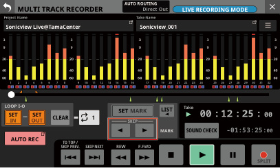
Moving by selecting from a list
1.When stopped, paused or playing back, tap the ![]() button on the MULTI TRACK RECORDER Screen to open a window that shows mark list information.
button on the MULTI TRACK RECORDER Screen to open a window that shows mark list information.
2.Turn LCD knob 1 to select the mark at the desired destination time.
3.Tap the LOCATE button to move (skip) to the position of the selected mark.
NOTE
Tap the IN or OUT point button in the mark list to move (skip) to the corresponding time.
Marks can be cleared when stopped, paused or playing back.
The following two methods are available.
Selecting from a list and deleting
1.When stopped, paused or playing back, tap the ![]() button on the MULTI TRACK RECORDER Screen to open a window that shows mark list information.
button on the MULTI TRACK RECORDER Screen to open a window that shows mark list information.
2.Turn LCD knob 1 to select the mark to be deleted.
3.Tap the DELETE button to delete that mark.
NOTE
Repeat steps 2 – 3 to delete multiple marks.
Moving to the mark and deleting
Move to the position of the mark to be deleted and tap the SET MARK button on the MULTI TRACK RECORDER Screen to delete that mark.
When a mark is deleted, a pop-up will appear on the display.
View the setting states of an IF-ST2110 (ST 2110 card) and other information on this screen.
Audio Network Config. page
This shows the setting state of the IF-ST2110 (ST 2110 card).
HOME (Source / Destination) page
This shows the transmission/reception states of the IF-ST2110 (ST 2110 card).
Tap Menu Screen > Rear Panel Setup > ST 2110 Setup to open this page.
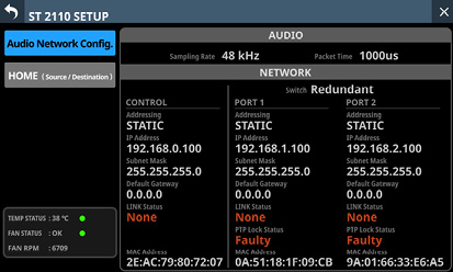
ATTENTION
Only one IF-ST2110 card can be used at a time. If two IF-ST2110 cards are installed, only the one in SLOT 1 can be used.
After the power is turned on, an installed IF-ST2110 (ST 2110 card) needs about 2 1/2 minutes before it can input and output audio. This time will vary according to the setup of the network used by the IF-ST2110.
.jpg)
Page selection buttons
Tap these buttons to switch the page shown.
|
Button appearance |
Content |
|
Audio Network Config. |
Shows audio and network setting states |
|
HOME (Source / Destination) |
Shows lists of source and destination streams |
Status display
This shows the status of the IF-ST2110.
TEMP STATUS
A temperature indicator is shown.
|
Indicator |
TEMP STATUS indicator |
Meaning |
|
Green |
OK |
Temperature is within normal range (81.9ºC or lower) |
|
Yellow |
ALERT |
Temperature is almost outside normal range (82.0ºC – 84.9ºC) |
|
Red |
FAILURE |
Temperature is not in normal range (85.0ºC or higher) |
FAN STATUS, FAN RPM
These show a cooling fan operation status indicator and its rotation speed.
|
Indicator |
FAN STATUS |
Meaning |
|
Green |
OK |
Normal |
|
Red |
FAILURE |
Malfunctioning |
AUDIO setting states
This shows the status of IF-ST2110 audio signals and clock.
|
Item |
Content |
|
Sampling rate |
This shows the sampling frequency setting for the IF-ST2110. |
|
Packet Time |
This shows the audio data packet time setting. |
IF-ST2110 NETWORK status (CONTROL)
This shows the setting state of the IF-ST2110 CONTROL connector.
|
Item |
Content |
|
Addressing |
This shows the IP address setting mode name of the CONTROL connector. |
|
IP Address |
If the Addressing item is set to “AUTO”, this will show the assigned IP address. If it is set to “STATIC”, this will show the IP address set by the user. |
|
Subnet mask |
If the Addressing item is set to “STATIC”, this will show the subnet mask set by the user. NOTE If the Addressing item is set to “AUTO”, the subnet mask will not be shown. |
|
Default Gateway |
If the Addressing item is set to “STATIC”, this will show the default gateway set by the user. NOTE If the Addressing item is set to “AUTO”, a default gateway will not be shown. |
|
LINK Status |
This shows the CONTROL connector link status. This will be shown in red if there is a problem with transmission. |
|
MAC Address |
This shows the MAC address of the CONTROL connector. |
IF-ST2110 NETWORK status (PORT 1 / PORT 2)
This shows the setting states of the IF-ST2110 PORT 1 and PORT 2 connectors.
|
Item |
Content |
|
Switch |
This shows whether the SMPTE ST 2022-7 (redundant system) function is enabled or disabled.
|
|
Addressing |
This shows the name of the IP address setting mode for the PORT connector. |
|
IP Address |
If the Addressing item is set to “AUTO”, this will show the assigned IP address. If it is set to “STATIC”, this will show the IP address set by the user. |
|
Subnet mask |
If the Addressing item is set to “STATIC”, this will show the subnet mask set by the user. NOTE If the Addressing item is set to “AUTO”, the subnet mask will not be shown. |
|
Default Gateway |
If the Addressing item is set to “STATIC”, this will show the default gateway set by the user. NOTE If the Addressing item is set to “AUTO”, a default gateway will not be shown. |
|
LINK Status |
This shows the PORT connector link status. This will be shown in red if there is a problem with transmission. |
|
PTP Lock Status |
This shows the PTP synchronization state.
|
|
MAC Address |
This shows the MAC address of the PORT connector. |
HOME (Source / Destination) page
.jpg)
Page selection buttons
Tap these buttons to switch the page shown.
|
Button appearance |
Content |
|
Audio Network Config. |
Shows audio and network setting states |
|
HOME (Source / Destination) |
Shows lists of source and destination streams |
Source area
This shows a list of streams transmitted from the IF-ST2110 (ST 2110 card).
The STATUS items show the stream connection states of the IF-ST2110 expansion card medoa ports (PORT 1 / PORT 2).
|
Indicator |
Connection status |
|
|
The transmission status is good. |
|
|
Some connections have problems. The number of problems is shown with a numeral. |
|
|
Connection has not been achieved. The number of problems is shown with a numeral. |
NOTE
Tapping a number will open a message with details about the problem.
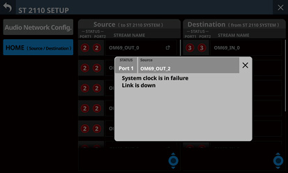
The STREAM NAME item shows the name assigned to the Source stream.
Tap the ![]() icon to open the Source Information window.
icon to open the Source Information window.
.jpg)
Labels of Sonicview modules that are transmission sources
Slot number and channel in slot of transmission sources
Channels in streams transmitted from IF-ST2110 (ST-2110 card)
Scroll knob and scrollbar
This scroll bar shows the position of the setting items currently shown on the screen relative to the Source area () stream list.
NOTE
To view setting items not shown in the Source area (), swipe the setting items area up and down to scroll the screen.
LCD knob 5, which is lit light blue, can also be turned to scroll the screen.
Destination area
This shows a list of streams being received by the IF-ST2110 (ST 2110 card).
The STATUS items show the stream connection states of the IF-ST2110 expansion card medoa ports (PORT 1 / PORT 2).
|
Indicator |
Connection status |
|
|
The transmission status is good. |
|
|
Some connections have problems. The number of problems is shown with a numeral. |
|
|
Connection has not been achieved. The number of problems is shown with a numeral. |
NOTE
Tapping a number will open a message with details about the problem.
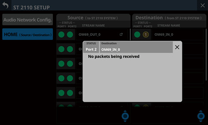
The STREAM NAME item shows the name assigned to the Destination stream.
Scroll knob and scrollbar
This scroll bar shows the position of the setting items currently shown on the screen relative to the Destination area () stream list.
NOTE
To view setting items not shown in the Destination area (), swipe the setting items area up and down to scroll the screen.
LCD knob 8, which is lit light blue, can also be turned to scroll the screen.
Using TASCAM Sonicview Control to control this unit
This unit can be controlled remotely over a network using the dedicated TASCAM Sonicview Control application.
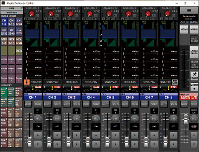
Make network settings to connect this unit and TASCAM Sonicview Control on the Network Setup Screen. (See “Network Setup screen”.)
NOTE
For details about the TASCAM Sonicview Control application, see its manual.
TASCAM Sonicview Control and its application manual can be downloaded from the TASCAM website.
Sonicview 16XP
https://tascam.com/us/product/sonicview_16xp/support
Sonicview 24XP
https://tascam.com/us/product/sonicview_24xp/support
Controlling this unit with the Ember+ remote control protocol
Number of Ember+ devices that can be connected
Multiple Ember+ devices can be connected to this unit, and connection with 12 Ember+ devices has been confirmed.
However, the actual number of devices that can be connected could vary depending on the network environment.
Monitoring and control overview
This unit can be monitored and controlled over a network using Ember+.
For detailed operation procedures, see “TASCAM Sonicview 16/24 Remote Control Specifications (Ember+ Edition)”.
This unit can have a maximum of 12 Ember+ devices connected to it simultaneously.
NOTE
Ember+ is a control protocol developed by the Lawo Group.
Note about meter data acquisition
Meter data cannot by acquired with Ember+.
For detailed specifications related to meter data acquisition, see “TASCAM Sonicview 16/24 Remote Control Specifications (Meter data Protocol Edition)”.
This unit can acquire meter data with a maximum of 12 devices connected to it simultaneously.
These specifications can be downloaded from the following TASCAM website pages.
TASCAM Sonicview 16/24 Remote Control Specifications (Ember+ Edition)
TASCAM Sonicview 16/24 Remote Control Specifications (Meter data Protocol Edition)
Sonicview 16
https://tascam.com/us/product/sonicview_16xp/support
Sonicview 24
https://tascam.com/us/product/sonicview_24xp/support
Monitoring this unit with SNMP
SNMP (Simple Network Management Protocol) is a protocol that monitors and controls communication devices on a network based on a management information database called an “MIB”.
This unit supports SNMPv1 and SNMPv2, enabling its status to be checked over a network.
When SNMP management software can be used, by installing it on a computer, this unit can be monitored from that computer.
For details, check the operation manual of the software being used.
List of parameters supported by this unit for SNMP monitoring
|
Clock Status |
|
Sampling Rate |
|
Clock Master |
|
Slot 1 |
|
Slot 2 |
|
Media SD |
|
Media USB |
|
Recorder Status |
|
Player Status |
|
System Temperature |
|
System Temperature Status |
|
CPU Temperature |
|
CPU Temperature Status |
|
DSP Temperature |
|
DSP Temperature Status |
|
FAN Speed (RPM) |
|
FAN Status |
|
MTR Status |
|
System Version |
|
error list |
This is a special operation mode for calibrating faders and touchscreens.
Depending on the operating conditions and environment, discrepancies could develop in fader reading and movement positions as well as touchscreen detection positions.
These discrepancies can be adjusted through calibration.
Starting and ending calibration mode
Starting up in calibration mode
While pressing the TALKBACK and SENDS ON FADER keys, turn the unit power on.
Keep pressing the TALKBACK and SENDS ON FADER keys until the CALIBRATION MODE Screen appears on the right touchscreen.
.jpg)
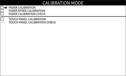
Ending calibration mode
Turn the unit power off.
The CALIBRATION MODE Screen opens on the right touchscreen.
Except during the following menu operations, the touchscreens other than the right one will be completely off (appear black).
TOUCH PANEL CALIBRATION
TOUCH PANEL CALIBRATION CHECK
Calibration mode menu operations
1.Turn LCD knob 1 below the right touchscreen to move the cursor (<<) on the CALIBRATION MODE screen to the desired item.
.jpg)
2.After moving the cursor (<<) to the desired item, press LCD knob 1 to select that item.
3.After the selected item completes properly, a check ( ![]() ) will be added to the corresponding checkbox and the cursor will move to the next item.
) will be added to the corresponding checkbox and the cursor will move to the next item.
NOTE
Pressing the HOME key while an item is being executed will cancel that item and reopen the CALIBRATION MODE Screen.
The fader position read value (A/D conversion value) and top panel fader scale value can be calibrated.
ATTENTION
During fader calibration, step 2 below must be executed for every channel fader and the MASTER fader. Be aware that separate calibration is not possible.
1.Turn LCD knob 1 to move the cursor (<<) to “FADER CALIBRATION”, and then press LCD knob 1.
This opens the FADER CALIBRATION operation screen.
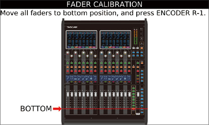
2.The positions of the faders to be calibrated are indicated by a red line on the operation screen.
Manually move each fader to the scale position indicated on the operation screen so the fader positions are visually aligned.
After completing each positioning, press LCD knob 1 (ENCODER R-1) to confirm the scale position. (This will be recorded in the internal memory of the unit.)
The order of fader scale positions to be calibrated is as follows.
−∞ (BOTTOM) −60 dB −20 dB 0 dB 10 dB (TOP)
During calibration of each fader, the read values of faders will be shown on the corresponding channel screens.
3.Fader calibration is complete after 10 dB (TOP) fader positioning is conducted.
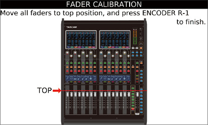
Press LCD knob 1 (ENCODER R-1) to reopen the CALIBRATION MODE Screen.
A check ( ![]() ) will be added to the FADER CALIBRATION item and the cursor (<<) will move to the next item.
) will be added to the FADER CALIBRATION item and the cursor (<<) will move to the next item.
NOTE
Pressing the HOME key while calibration is being conducted will cancel calibration and reopen the CALIBRATION MODE Screen. In this case, a check ( ![]() ) will not be added to that item.
) will not be added to that item.
Speed calibration of each fader can be conducted automatically.
1.Turn LCD knob 1 to move the cursor (<<) to “FADER SPEED CALIBRATION”, and then press LCD knob 1.
This opens the parameter screen for each fader.
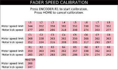
|
Model |
Meaning |
|
Sonicview 16 |
L/R 1–8, MASTER |
|
Sonicview 24 |
L/C/R 1–8, MASTER |
2.Press the LCD 1 knob (ENCODER R-1) for the parameter screen to start fader speed calibration.
“Calibrating…” will be shown at the top of the parameter screen during speed calibration.
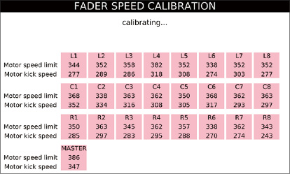
There are multiple calibration phases. Please wait for all of them to complete.
The color bar LED at the top of the fader section will light as follows according to the progress of the calibration process.
Red: beginning of corresponding calibration phase
Orange: middle of corresponding calibration phase
Green: corresponding calibration phase complete
One calibration phase is complete when all of the color bar LEDs at the top of the fader section become green. Calibration will automatically continue to the next phase.
3.After speed calibration has completed for all faders, the CALIBRATION MODE Screen will reopen, a check ( ![]() ) will be added next to the FADER SPEED CALIBRATION item, and the cursor (<<) will move to the next item.
) will be added next to the FADER SPEED CALIBRATION item, and the cursor (<<) will move to the next item.
NOTE
Pressing the HOME key while calibration is being conducted will cancel calibration and reopen the CALIBRATION MODE Screen. In this case, a check ( ![]() ) will not be added to that item.
) will not be added to that item.
The faders that have been calibrated can be checked to confirm that they can move to the correct positions.
1.Turn LCD knob 1 to move the cursor (<<) to “FADER CALIBRATION CHECK”, and then press LCD knob 1.
This opens the FADER CALIBRATION CHECK operation screen.
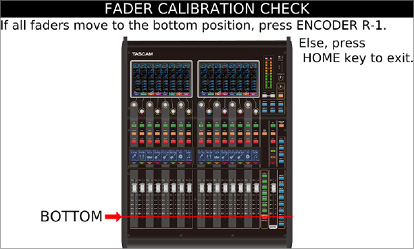
2.The movement positions of the faders to be checked are indicated by a red line on the operation screen.
First, each fader will be moved automatically to the “∞ (BOTTOM)” position.
NOTE
The confirmation order of fader movement positions is as follows.
−∞ (BOTTOM) 0 dB −60 dB 10 dB (TOP) −20 dB
3.Visually confirm the movement position of each fader.
If there are no problems with the fader movement positions, press LCD knob 1 (ENCODER R-1).
Each time LCD knob 1 (ENCODER R-1) is pressed, each fader will automatically move to the position indicated on the operation screen. Confirm visually that it moves to the correct position.
If there is a problem with a fader movement position, press the HOME Key to cancel the confirmation process. Then, conduct calibration again (“FADER CALIBRATION”).
During confirmation of each fader, the movement positions of faders will be shown on the corresponding channel screens.
4.The fader calibration check is complete after the −20 dB fader movement position is confirmed.
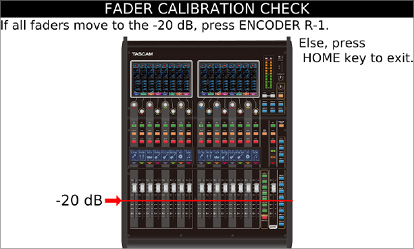
Press LCD knob 1 (ENCODER R-1) to reopen the CALIBRATION MODE Screen.
A check ( ![]() ) will be added to the FADER CALIBRATION CHECK item and the cursor (<<) will move to the next item.
) will be added to the FADER CALIBRATION CHECK item and the cursor (<<) will move to the next item.
NOTE
Pressing the HOME key during operation confirmation will cancel it and reopen the CALIBRATION MODE Screen. In this case, a check ( ![]() ) will not be added to that item.
) will not be added to that item.
The touch panel functions of the touchscreens can be calibrated.
The Sonicview 16 has 2 touchscreens
The Sonicview 24 has 3 touchscreens
1.Turn LCD knob 1 to move the cursor (<<) to “TOUCH PANEL CALIBRATION”, and then press LCD knob 1.
First, the TOUCH PANEL CALIBRATION Screen will open on the left touchscreen.
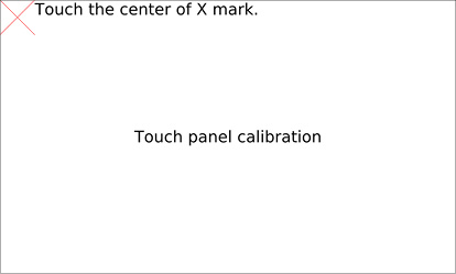
2.Use a stylus* to touch the center of the “” mark momentarily.
A calibration value will be read from the position where the stylus is removed from the screen.
*Use a stylus designed for touchscreens to conduct calibration.
Pressing or tapping the surface of a touchscreen with something made of metal (for example, a fine-tipped screwdriver) could damage the surface and make touch operation unusable.
3.Touch panel calibration is conducted on three corners of the touchscreen in the following order.
Top left (1st) top right (2nd) right (3rd)
When a “” mark is shown in each corner, following the instructions on the screen, momentarily touch the center of the with the stylus.
After calibration of one touchscreen is complete, a “” mark will appear in the corner of the next touchscreen.
.jpg)
4.After calibration has completed for all touch panels, the CALIBRATION MODE Screen will reopen, a check ( ![]() ) will be added next to the TOUCH PANEL CALIBRATION item, and the cursor (<<) will move to the next item.
) will be added next to the TOUCH PANEL CALIBRATION item, and the cursor (<<) will move to the next item.
NOTE
Pressing the HOME key while calibration is being conducted will cancel calibration and reopen the CALIBRATION MODE Screen. In this case, a check ( ![]() ) will not be added to that item.
) will not be added to that item.
The positions captured by touchscreen calibration can be checked.
The Sonicview 16 has 2 touchscreens
The Sonicview 24 has 3 touchscreens
ATTENTION
Conduct a TOUCH PANEL CALIBRATION CHECK after completing a TOUCH PANEL CALIBRATION.
If a TOUCH PANEL CALIBRATION has not been conducted, accurate confirmation of positions is not possible.
1.Turn LCD knob 1 on the CALIBRATION MODE Screen to move the cursor (<<) to the desired item, and then press LCD knob 1.
2.First, the TOUCH PANEL CALIBRATION CHECK Screen will open on the left touchscreen.
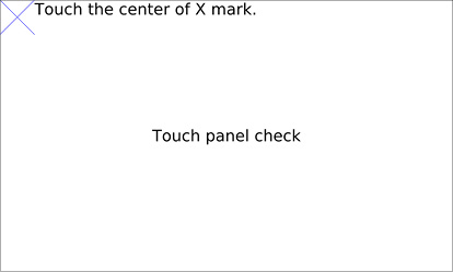
3.Use a stylus* to touch the center of the “” mark.
*Use a stylus designed for touchscreens to conduct calibration.
Pressing or tapping with something made of metal (for example, a fine-tipped screwdriver) could damage the surface of the touchscreen and make touch operation unusable.
4.Touch panel confirmation is conducted on three corners of the touchscreen in the following order.
Top left (1st) top right (2nd) right (3rd)
After “—” marks appear in each corner and all calibration is complete, “” marks will appear in the corners of the next touchscreen.
.jpg)
5.If the position of touch panel calibration and the touched position are correct, the “” mark in the touched position will disappear and a “” mark will appear in the next confirmation position.
If the touched position is offset from the center of the “” mark, a guide line will be shown in the X and Y directions while touching continues.
If the guide line is moved while touching, and the point of intersection of the “” mark and guide match and calibration has been successful, the guide line and the “” mark will disappear.
If the point of intersection of the touched point and the guide line are separated, touch panel calibration might not have been completed properly.
In this case, redo touch panel calibration from the beginning, and then check the touch panel calibration again.
6.After checking calibration has completed for all touch panels, the CALIBRATION MODE Screen will reopen, a check ( ![]() ) will be added next to the TOUCH PANEL CALIBRATION CHECK item, and the cursor (<<) will move to the next item.
) will be added next to the TOUCH PANEL CALIBRATION CHECK item, and the cursor (<<) will move to the next item.
NOTE
Pressing the HOME key during operation confirmation will cancel it and reopen the CALIBRATION MODE Screen. In this case, a check ( ![]() ) will not be added to that item.
) will not be added to that item.
This unit has shortcuts that combine the simultaneous use of keys and the touchscreen, for example, to easily execute certain operations.
Pressing something at the same time as the HOME key will reset that parameter to its standard value. (Brightness adjustment is excluded.)
|
Shortcut operation |
Explanation |
|
Press a SEL key while pressing the HOME key on the top panel |
|
|
Tap the SEND level area on the touchscreen while pressing the HOME key on the top panel |
This sets the following parameters to 0 dB.
|
|
Tap the PAN area on the touchscreen while pressing the HOME key on the top panel |
This sets the following pan/balance settings to center (C).
|
|
Tap the EQ gain area on the touchscreen while pressing the HOME key on the top panel |
This sets the EQ gain settings to 0 dB on the MODULE (EQ) Screens of each module. |
|
Turn any LCD knob while pressing the HOME key on the top panel |
This adjusts the brightness of all the touchscreens, channel screens, various indicators and the lamp connected to the LAMP connector on the rear panel at the same time. |
|
Press and turn any LCD knob while pressing the HOME key on the top panel |
This adjusts the brightness of all the touchscreens and channel screens at the same time. |
While pressing the MENU key, press a key to open its settings screen. (Adjusting contrast is excluded.)
|
Shortcut operation |
Explanation |
|
|
Press the TALKBACK key while pressing the MENU key on the top panel |
This opens the TALKBACK page of the TALKBACK / MONITOR / SOLO / OSC SETUP Screen on the touchscreen. |
|
|
Press the SOLO or SOLO CLEAR key while pressing the MENU key on the top panel |
This opens the SOLO/OSCILLATOR page of the TALKBACK / MONITOR / SOLO / OSC SETUP Screen on the touchscreen. |
|
|
Press a LAYER KEYS 1–7 while pressing the MENU key on the top panel |
This opens the Layer Key SETUP Screen for the selected layer on the touchscreen. |
|
|
Press a USER KEYS A–F or USER KEYS 1–12 key while pressing the MENU key on the top panel |
This will open one of the following screens that corresponds to the function assigned to USER KEYS A–F or USER KEYS 1–12. |
|
|
USER key function |
Screen recalled by MENU+USER key |
|
|
Unassigned |
USER KEY setting screen for the depressed USER key |
|
|
Snapshot |
Snapshot List Screen |
|
|
Monitor |
MONITOR 1/2 page of the TALKBACK / MONITOR / SOLO / OSC SETUP screen |
|
|
SOLO |
SOLO/OSCILLATOR page of the TALKBACK / MONITOR / SOLO / OSC SETUP Screen |
|
|
OSC |
SOLO/OSCILLATOR page of the TALKBACK / MONITOR / SOLO / OSC SETUP Screen |
|
|
Talkback |
TALKBACK page of the TALKBACK / MONITOR / SOLO / OSC SETUP Screen |
|
|
LED Indication |
Nothing will happen |
|
|
Sends On Fader |
Nothing will happen |
|
|
Recorder/Player |
RECORDER/PLAYER Screen |
|
|
MTR |
MULTI TRACK RECORDER Screen |
|
|
Insert ON/OFF |
MODULE (OVERVIEW) Screen |
|
|
Send On/Off |
MODULE (SEND/ PAN) Screen for module where Parameter 1 is set |
|
|
Mute |
Mute Group Assign Screen if the operation target is Mute Group 1–8. Nothing if the operation target is not Mute Group 1–8. |
|
|
Tap Tempo |
FX MODULE (FX) Screen for the assigned number |
|
|
Screen |
Screen where Parameter 1 and 2 are set |
|
|
Turn an LCD knob while pressing the MENU key on the top panel |
This adjusts the contrast of the channel screen that corresponds to that knob. |
|
If you are having trouble with the operation of this unit, please try the following before seeking repair.
If these measures do not solve the problem, please contact the store where you purchased this unit or TASCAM customer support service.
Power will not turn on
Confirm that the power plug and other connectors are inserted completely.
No sound is output
Confirm that the input and output routings and bus assignments are correct.
Check connections with the monitoring system again. Check the volume of the amplifier as well.
Confirm that the monitoring sources are correctly selected.
Are that channel faders raised to suitable levels?
Confirm that the MASTER fader is raised to a suitable level.
Confirm that the headphones or MONITOR OUT volume is raised to a suitable level.
Are any of the channel MUTE () or SOLO () keys on?
There is noise
Confirm that the connection cables do not have connection issues.
Changed settings are forgotten
This unit saves settings at one-minute intervals.
Since saving could fail depending on when the power is turned off, use the Save Current Settings item on the Menu Screen to save the current settings in the internal memory before turning the power off.
Touchscreen operations are not possible
If the system detects that touchscreen operations have stopped working, the following message will appear on the channel screens.
On Sonicview 16XP

On Sonicview 24XP

Follow the instructions in the message, and press and hold the HOME and MENU keys for at least five seconds to restart the system and enable touchscreen operation.
Audio will continue to be output without interruption, but fader and mute operations will not be possible while restarting.
Since restarting will take some time to complete, conduct it when it will not cause trouble.
Fader, key and LCD knob operations are not possible
If the system detects that fader, key and LCD knob operations have stopped working, the following message will appear on the touchscreen.
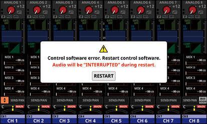
Tap the RESTART buttons to open a restart confirmation window.
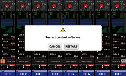
Tap the RESTART button on the confirmation screen to restart the system and enable fader, key and LCD knob operations.
Note that while restarting audio output will stop.
Since restarting will take some time to complete, conduct it when it will not cause trouble.
Parameters on the touchscreen can be operated but do not affect the sound
Trouble might have occurred with the signal processing device. If the system detects trouble with the signal processing control device, the following message will appear on the touchscreen and the channel screen.
On Sonicview 16XP

On Sonicview 24XP

Tap the RESTART buttons to open a restart confirmation window.
Tap the RESTART button on the confirmation screen to restart the system and enable proper LCD knob operations. Alternatively, follow the instructions in the message on the Channel Screen, and press and hold the HOME and MENU keys for at least five seconds to restart the system.
Note that while restarting audio output will stop.
Since restarting will take some time to complete, conduct it when it will not cause trouble.
Simultaneous processing capabilities
Inputs: 52
Mono: 40
Stereo: 2 pairs
FX Return: 4 pairs
Buses: 32
MIX buses (AUX/GROUP switchable): 22
MAIN L/R bus: 1 stereo
FX SEND buses: 4 pairs
Internal FX: 4
Input ports
96 kHz: 160 ports maximum (Sonicview 24XP), 152 ports maximum (Sonicview 16XP)
48 kHz: 256 ports maximum (Sonicview 24XP), 248 ports maximum (Sonicview 16XP)
MIC/LINE: 24 (Sonicview 24XP), 16 (Sonicview 16XP)
ST IN (RCA): 4 (2 stereo)
Dante: 32 (96 kHz), 64 (48 kHz)
SLOT: 32 × 2 slots (96 kHz), 64 × 2 slots (48 kHz)
USB AUDIO: 32
Internal player: 2 (1 stereo)
OSC: 1
TALKBACK: 1
Output ports
96 kHz: 148 ports maximum
48 kHz: 244 ports maximum
OUTPUT (analog): 16
Dante: 32 (96 kHz), 64 (48 kHz)
SLOT: 32 × 2 slots (96 kHz), 64 × 2 slots (48 kHz)
USB AUDIO: 32
MONITOR OUT (analog): 2 (1 stereo)
Internal recorder: 2 (1 stereo)
Input and output ports
Analog insert I/O: 2
MIC/LINE inputs 15/16 (Sonicview 24XP)
MIC/LINE inputs 7/8 (Sonicview 16XP)
Signal processing
Mixer engine: 96kHz/54-bit floating-point arithmetic
ADC: 96 kHz/32-bit
DAC: 96 kHz/24-bit
Digital I/O sampling frequencies: 96 kHz, 48 kHz
Signal Delay
|
48 kHz |
ms |
Routing details |
|
A to A |
0.510 |
MIC/LINE IN |
|
A to A |
0.620 |
MIC/LINE IN |
|
D to D |
0.498 |
SLOT MADI IN |
|
A to D |
0.458 |
MIC/LINE IN |
|
D to A |
0.571 |
SLOT MADI IN |
|
D to A |
0.666 |
SLOT MADI IN |
|
96 kHz |
ms |
Routing details |
|
A to A |
0.510 |
MIC/LINE IN |
|
A to A |
0.620 |
MIC/LINE IN |
|
D to D |
0.104 |
SLOT MADI IN |
|
A to D |
0.261 |
MIC/LINE IN |
|
D to A |
0.374 |
SLOT MADI IN |
|
D to A |
0.468 |
SLOT MADI IN |
0 dBu = 0.775 Vrms
Mic amp EIN (equivalent input noise)
−128 dBu or less
Frequency response
MIC/LINE IN to OUTPUT (Analog)
20 Hz - 40 kHz: +0 dB, −1.0 dB (JEITA)
Dynamic range
108 dB or more (MIC/LINE IN to OUTPUT (Analog), PAD = OFF, TRIM at minimum, D.Ref = −20 dBFS, Clock master = INT, JEITA)
110 dB or more (MIC/LINE IN to Dante OUT, PAD = OFF, TRIM at minimum, JEITA)
112 dB or more (Dante IN to OUTPUT (Analog), Clock master = INT, JEITA)
Distortion
0.002% or less (MIC/LINE IN to OUTPUT (Analog), Input at +4 dBu, PAD = OFF, TRIM at minimum, JEITA)
0.002% or less (MIC/LINE IN to Dante OUT, Input at +4 dBu, PAD = OFF, TRIM at minimum, JEITA)
0.002% or less (Dante IN to OUTPUT (Analog), Input at 0 dBFS, JEITA)
Crosstalk
100 dB or more (MIC/LINE IN to OUTPUT (Analog), 1 kHz sine wave, JEITA)
D.Ref: Digital Reference Level setting
Analog audio input and output ratings
0 dBu = 0.775 Vrms, 0 dBV = 1 Vrms
MIC/LINE input jacks
Sonicview 16XP: 1-16
Sonicview 24XP: 1-24
Connectors: XLR-3-31 equivalent (1: GND, 2: HOT, 3: COLD)
Input levels:
PAD off
Maximum input level: +12 dBu (TRIM at minimum)
Minimum input level: −62 dBu (TRIM at maximum)
PAD on
Maximum input level: +32 dBu (TRIM at minimum)
Minimum input level: −42 dBu (TRIM at maximum)
Input impedance: 5.0 kΩ or higher
NOTE
+48V phantom power can be supplied to each MIC/LINE input jack separately.
LINE IN (BAL) jacks
Sonicview 16XP: 9-16
Sonicview 24XP: 17-24
Connectors:6.3mm (1/4”) TRS phone jacks (Tip: HOT, Ring: COLD, Sleeve: GND)
Input levels:
PAD off
Maximum input level: +12 dBu (TRIM at minimum)
Minimum input level: −62 dBu (TRIM at maximum)
PAD on
Maximum input level: +32 dBu (TRIM at minimum)
Minimum input level: −42 dBu (TRIM at maximum)
Input impedance: 5.0 kΩ or higher
INSERT jacks
Sonicview 16XP: 7-8
Sonicview 24XP: 15-16
Connectors:6.3mm (1/4”) TRS phone jacks (Tip: SEND, Ring: RETURN, Sleeve: GND)
RETURN (Ring)
Maximum input level: +18 dBu
Nominal input level: −2 dBu
Input impedance: 5.0 kΩ or higher
SEND (Tip)
Maximum output level: +18 dBu
Nominal output level: −2 dBu
Output impedance: 100 Ω or less
TALKBACK input jack
Connectors: XLR-3-31 equivalent (1: GND, 2: HOT, 3: COLD)
Maximum input level: +10 dBu
Minimum input level: −65 dBu
Gain adjustment range: 0 – 55 dB
Input impedance: 5.0 kΩ or higher
NOTE
+48V phantom power can be supplied.
ST IN 1–2 L/R jacks
Connectors: RCA pin jacks
Maximum input level: +6 dBV
Nominal input level: −10 dBV
Headroom: 16 dB
Input impedance: 10 kΩ or higher
OUTPUT 1-16 jacks
Connectors: XLR-3-32 equivalent (1: GND, 2: HOT, 3: COLD)
Output impedance: 100 Ω or less
Nominal output level:
+6 dBu (D.Ref: −9 dBFS, A.Ref:+6 dBu)
+4 dBu (D.Ref: −14/−16/−18/−20 dBFS, A.Ref: +4 dBu)
0 dBu (D.Ref: −18/−20 dBFS, A.Ref: 0 dBu)
Maximum output level:
+15 dBu (D.Ref: −9 dBFS, A.Ref: +6 dBu)
+18 dBu (D.Ref: −18 dBFS, A.Ref: 0 dBu)
+20 dBu (D.Ref: −20 dBFS, A.Ref: 0 dBu)
+18 dBu (D.Ref: −14 dBFS, A.Ref: +4 dBu)
+20 dBu (D.Ref: −16 dBFS, A.Ref: +4 dBu)
+22 dBu (D.Ref: −18 dBFS, A.Ref: +4 dBu)
+24 dBu (D.Ref: −20 dBFS, A.Ref: +4 dBu)
D.Ref: Digital Reference Level setting
A.Ref: Analog Reference Level setting
MONITOR OUT L/R jacks
Connectors: XLR-3-32 equivalent (1: GND, 2: HOT, 3: COLD)
Maximum output level: +24 dBu
Nominal output level: +4 dBu
Output impedance: 100 Ω or less
Phones jack
Connectors:6.3mm (1/4”) stereo phone jack, 3.5mm (1/8”) stereo mini jack
Maximum output: 100 mW + 100 mW (32Ω load, when connected to only one jack)
Digital audio input/output ratings
Dante PRIMARY/SECONDARY connectors
Connector: etherCON Cat5e compatible connector*
Transmission protocol: Dante
Gigabit Ethernet standard: 1000BASE-T (IEEE 802.3ab)
Cables: category 5e or faster STP cables
*etherCON is a registered trademark of Neutrik AG.
USB Audio
Sampling Rate: 48 kHz, 96 kHz
Bit Depth: 32 bit/24 bit/16 bit
Number of inputs: 32 channels (Input to this unit)
Number of outputs: 32 channels (Output from this unit)
FOOTSWITCH jack
Connector: 6.3mm (1/4”) TS phone jack (Tip: HOT, Sleeve: GND)
ETHERNET connector
Connector: RJ-45
Compatible standards: 100BASE-TX, 1000BASE-T
GPIO connector
Connector: 25-pin D-sub (8-in/8-out, female, inch-standard)
See “GPIO connector overview” for details about the GPIO connector and assignments.
Other input and output specifications
USB port (Top panel)
Connector: USB Type-C
Protocol: USB 2.0 HIGH SPEED (480 Mbps)
USB port (Rear panel)
Connector: USB Type-B
Protocol: USB 2.0 HIGH SPEED (480 Mbps)
LAMP jack
Connector: XLR 4-pin female (pin 4: +12V, pin 3: GND)
Power supply voltage: 0 V – +12 V
Maximum output: 5 W
WORD IN connector
Connector: BNC
Input level: 0.5–5 Vp-p
Input impedance: 75 Ω ±10% (termination resistance on)*
Input frequency: 48, 96 kHz
Allowable frequency deviation: ±100 ppm
*See “ WORD OUT Mode button” in “SYNC CLOCK screen” for details about turning termination resistance on/off.
WORD THRU/OUT connector
Connector: BNC
Output level: equivalent to 5V TTL
Output frequency: 48, 96 kHz
See “ WORD OUT Mode button” in “SYNC CLOCK screen” for details about through/word output switching.
Stereo Recorder specifications
Recording media
SDHC cards (8GB–32GB, Class 10 or more)
SDXC cards (64GB–128GB, Class 10 or more)
USB flash drives (8GB–128GB, playback only)
NOTE
Lists of SD cards and USB flash drives that have been confirmed for use with this unit can be found on the TASCAM website.
Sonicview 16XP
https://tascam.com/us/product/sonicview_16xp/support
Sonicview 24XP
https://tascam.com/us/product/sonicview_24xp/support
Please use SD cards and USB flash drives included in these lists. You can also contact TASCAM customer support.
File System
SDHC card: FAT32
SDXC card: exFAT
USB flash drives: FAT32/exFAT
Recording/playback formats
BWF/WAV
Recording: 48/96 kHz, 24-bit, 2-channel
Playback: 48/96 kHz, 16/24-bit, 2-channel
MP3
Playback: 44.1/48 kHz, 32–320 kbps, 2-channel
AAC
Playback: 44.1/48 kHz, 64–320 kbps, 2-channel
Multitrack Recorder specifications
Recording media
SDHC cards (8–32 GB, UHS-I or faster)
SDXC cards (64–512 GB, UHS-I or faster)
NOTE
A list of SD cards that have been confirmed for use with this unit can be found on our web site.
Sonicview 16XP
https://tascam.com/us/product/sonicview_16xp/support
Sonicview 24XP
https://tascam.com/us/product/sonicview_24xp/support
File System
SDHC card: FAT32
SDXC card: exFAT
Recording/playback formats
BWF/WAV (recording is always BWF), monophonic
Sampling frequency
48 or 96 kHz
Number of recording tracks
32 at 48kHz or 16 at 96kHz
Quantization bit depth
When recording: 24bit, 32bit
When playing: 16bit, 24bit, 32bit
Operating system and computer requirements
Check the TASCAM website for the latest information about supported operating systems.
Sonicview 16XP
https://tascam.com/us/product/sonicview_16xp/support
Sonicview 24XP
https://tascam.com/us/product/sonicview_24xp/support
ATTENTION
Operation with each OS was confirmed with standard system setups that met the following conditions. Operation is not guaranteed, however, with all systems that meet the following conditions.
Supported operating systems
Windows 11 64-bit
Windows 10 64-bit
Computer hardware requirements
Windows computer with a USB 2.0 (or higher) port*
*Operation is not guaranteed using the TASCAM driver with ARM64 CPUs.
Supported operating systems
macOS Ventura (13)
macOS Monterey (12)
macOS Big Sur (11)
macOS Catalina (10.15)
Computer hardware requirements
Mac with a USB 2.0 (or higher) port
Power
AC 100-240V, 50/60Hz
Power consumption
Sonicview 16XP: 65W
Sonicview 24XP: 85W
External dimensions
Sonicview 16XP: 472.0 x 228.1 x 554.4 mm
Sonicview 24XP: 690.8 x 228.1 x 554.4 mm
(width × height × depth)
Weight
Sonicview 16XP: 13 kg
Sonicview 24XP: 18 kg
Operating temperature range
0 – 40°C (32 – 104°F)
Illustrations in this reference manual might differ in part from the actual product.
Specifications and external appearance might be changed without notification to improve the product.
Sonicview 16XP
.jpg)
Sonicview 24XP
.jpg)
Sonicview 16XP/24XP Mixer Basic Parameters
Libraries
|
Name |
User |
Preset |
|
Snapshot |
128 |
1 |
|
MODULE INPUT |
128 |
2 |
|
MODULE FX RTN |
128 |
4 |
|
MODULE OUTPUT |
128 |
1 |
|
EQ |
128 |
18 |
|
GEQ |
128 |
0 |
|
GATE/EXP/DE-ESSER |
128 |
11 |
|
COMP/DUCKER |
128 |
12 |
|
FX |
128 |
14 |
Input Modules
|
Function |
Parameter |
steps |
Fine Step (when LCD knob turned without being pressed) |
Coarse Steps (when LCD knob turned while being pressed) |
|
|
Pre Amp |
Analog Gain |
When Analog Reference Level is +4 dBu and Digital Reference Level is -20 dBFS When PAD OFF: +12 dB – +66 dB When PAD ON: −8 dB – +46 dB NOTE See “Preamp analog gain for every reference level” for value ranges for various analog and digital reference levels. |
55 |
1 dB/click |
2 dB/click |
|
PAD |
OFF/ON |
||||
|
Phantom |
OFF/ON |
||||
|
OSC INPUT |
OFF/ON |
||||
|
Phase Sw |
Normal/Reverse |
||||
|
D.TRIM |
−50.0 dB – +20.0 dB |
141 |
0.5 dB/click |
2.0 dB/click |
|
|
HPF |
Switch |
OFF/ON |
|||
|
Freq |
20 Hz – 1.0 kHz |
69 |
1 point/click 1/12 oct/click |
3 step/click 1/4 oct/click |
|
|
DIRECT OUT |
Direct Out Switch |
OFF/ON |
|||
|
Direct Out Point |
INPUT/POST HPF/POST FADER |
||||
|
Direct Out Trim |
−20.0 dB – +20.0 dB |
401 |
0.1 dB/click |
2.0 dB/click |
|
|
INSERT |
Switch |
OFF/ON |
|||
|
Insert Point |
PRE EQ/PRE FADER |
||||
|
GATE/EXP/DE-ESSER |
Dynamics1 Switch |
OFF/ON |
|||
|
Dynamics1 Type |
GATE/EXPANDER/DE-ESSER |
||||
|
GATE |
Gate Threshold |
−80 dB – 0 dB |
81 |
1 dB/click |
4 dB/click |
|
Gate Range |
−60 dB – 0 dB |
61 |
1 dB/click |
3 dB/click |
|
|
Gate Attack |
0 ms – 125 ms |
126 |
1 ms/click |
5 ms/click |
|
|
Gate Hold |
0 ms – 990 ms |
100 |
10 ms/click |
50 ms/click |
|
|
Gate Decay |
5 ms – 5.00 s |
100 |
1 point/click |
5 point/click |
|
|
EXP |
Expander Threshold |
−60 dB – 0 dB |
61 |
1 dB/click |
3 dB/click |
|
Expander Ratio |
1:1, 2:1, 4:1, 8:1. 16:1. 32:1, 64: 1 |
7 |
1 point/click |
1 point/click |
|
|
Expander Knee |
HARD/MID/SOFT |
3 |
1 point/click |
1 point/click |
|
|
Expander Attack |
0 ms – 125 ms |
126 |
1 ms/click |
5 ms/click |
|
|
Expander ReleaseTime |
5 ms - 5.00 s |
100 |
1 point/click |
5 point/click |
|
|
DE-ESSER |
De-Esser Threshold |
−40 dB – 0 dB |
41 |
1 dB/click |
2 dB/click |
|
De-Esser Knee |
HARD/MID/SOFT |
3 |
1 point/click |
1 point/click |
|
|
De-Esser CenterFreq |
1.0 kHz – 10.0 kHz |
91 |
0.1 kHz/step |
0.5 kHz/step |
|
|
De-Esser Q |
1.04 – 17.31 |
28 |
1 point/click |
1 point/click |
|
|
4 BAND EQ |
Switch |
OFF/ON |
|||
|
Band Switch |
OFF/ON |
||||
|
Gain |
−18.0 – +18.0 |
361 |
0.1 dB/click |
1.0 dB/click |
|
|
Freq |
20 Hz – 20.0 kHz |
121 |
1 point/click 1/12 oct/click |
6 point/click 1/2 oct/click |
|
|
Q |
0.10 – 17.31 |
55 |
1 point/click |
3 point/click |
|
|
Type (LO) |
L.Shelf/Bell |
||||
|
Type (HI) |
H.Shelf/Bell/LPF |
||||
|
31 BAND GEQ |
Switch |
OFF/ON |
|||
|
Gain |
−18.0 – +18.0 |
361 |
0.1 dB/click |
1.0 dB/click |
|
|
COMP/DUCKER |
Switch |
OFF/ON |
|||
|
Type |
COMP/DUCKER |
||||
|
Key In Source |
SELF, CH 1–40, MIX 1–22, MAIN L/R |
||||
|
Key In Filter Switch |
OFF/ON |
||||
|
Key In Filter Type |
HPF/BPF/LPF |
||||
|
Key In Filter Freq |
20 Hz – 20.0 kHz |
121 |
1 point/click 1/12 oct/click |
6 point/click 1/2 oct/click |
|
|
Key In Filter Q |
0.10 – 17.31 |
55 |
1 point/click |
3 point/click |
|
|
COMP |
Comp Thresh |
−49 dB – 0 dB |
50 |
1 dB/click |
2 dB/click |
|
Comp Ratio |
1.00:1 – ∞:1 |
21 |
1 point/click |
1 point/click |
|
|
Comp Knee |
HARD HARD MID MID SOFT MID SOFT SMOOTH |
6 |
1 point/click |
1 point/click |
|
|
Comp Attack |
0.02 ms – 125 ms |
135 |
1 point/click |
5 point/click |
|
|
Comp Release |
5 ms – 5.00 s |
100 |
1 point/click |
5 point/click |
|
|
Comp Auto Makeup |
OFF/ON |
||||
|
Comp Output Gain |
0 dB – 20 dB |
21 |
1 dB/click |
1 dB/click |
|
|
DUCKER |
Ducker Threshold |
−60 dB – −6 dB |
5 |
6 dB/click |
6 dB/click |
|
Ducker Attenuation |
−∞, −24, −18, −12, −9, −6, −3 (dB) |
7 |
1 point/click |
1 point/click |
|
|
Ducker HoldTime |
0.1 sec – 5.0 sec |
50 |
0.1 sec/click |
0.1 sec/click |
|
|
Ducker Release Time |
0.1 sec – 5.0 sec |
50 |
0.1 sec/click |
0.1 sec/click |
|
|
DELAY |
Delay Switch |
OFF/ON |
|||
|
Delay Time |
0.0 meter – 117.3 meter 0.0 feet – 384.8 feet 0.00 msec – 341.32 msec |
0.1 meter/click 0.1 feet/click 0.02 msec/click |
2.0 meter/click 5.0 feet/click 5.00 msec/click |
||
|
Delay Point |
INPUT/PRE FADER |
||||
|
Delay Edit Unit |
meter/feet/msec |
||||
|
FADER LEVEL |
−∞ dB, −120 dB – +10.0 dB |
1024 |
1 point/click (−10 dB – +10 dB: 0.05 dB/click) |
40 point/click (−10 dB – +10 dB: 2 dB/click) |
|
|
MUTE |
OFF/ON |
||||
|
MAIN L/R Assign |
OFF/ON |
||||
|
PAN/BAL |
L100 – C – R100 |
201 |
1 point/click |
10 point/click |
|
|
IMAGE |
STEREO 100% – MONO – REVERSE 100% |
101 |
2%/click |
10%/click |
|
|
MODE |
STEREO/L-MONO/R-MONO |
3 |
|||
|
Send |
Send Level |
−∞ dB, −120 dB – +10.0 dB |
1024 |
1 point/click (−10 dB – +10 dB: 0.05 dB/click) |
40 point/click (−10 dB – +10 dB: 2 dB/click) |
|
Send Pan |
L100 – C – R100 |
201 |
1 point/click |
10 point/click |
|
|
Send Switch |
OFF/ON |
||||
|
Send Point |
PRE/POST |
||||
|
DCA |
8 DCAs |
||||
|
Mute Group |
8 Groups |
||||
|
Stereo Link |
OFF/ON |
||||
|
Auto Mixer |
Switch |
OFF/ON |
|||
|
Top Priority Switch |
OFF/ON |
||||
|
Top Priority Group |
A – D |
4 |
|||
|
Group Switch |
OFF/ON |
||||
|
Group Priority Switch |
OFF/ON |
||||
|
Group Lo Cut Switch |
OFF/ON |
||||
|
Group Lo Cut Freq |
125 Hz – 4.00 kHz |
61 |
1 point/click |
3 point/click |
|
|
Group Release Time |
5 msec – 1.00 sec |
70 |
1 point/click |
5 point/click |
|
|
Channel Group Assign |
A – D, --- |
5 |
|||
|
Channel Priority |
OFF/ON |
||||
|
Channel Weight |
−15 – +15 |
31 |
1 dB/click |
1 dB/click |
|
Preamp analog gain for every reference level
|
When Analog Reference Level is +6 dBu and Digital Reference Level is −9 dBFS |
|
|
When PAD OFF |
+3 dB – +57 dB |
|
When PAD ON |
−17 dB – +37 dB |
|
When Analog Reference Level is +4 dBu and Digital Reference Level is −20 dBFS |
|
|
When PAD OFF |
+12 dB – +66 dB |
|
When PAD ON |
−8 dB – +46 dB |
|
When Analog Reference Level is +4 dBu and Digital Reference Level is −18 dBFS |
|
|
When PAD OFF |
+10 dB – +64 dB |
|
When PAD ON |
−10 dB – +44 dB |
|
When Analog Reference Level is +4 dBu and Digital Reference Level is −16 dBFS |
|
|
When PAD OFF |
+8 dB – +62 dB |
|
When PAD ON |
−12 dB – +42 dB |
|
When Analog Reference Level is +4 dBu and Digital Reference Level is −14 dBFS |
|
|
When PAD OFF |
+6 dB – +60 dB |
|
When PAD ON |
−14 dB – +40 dB |
|
When Analog Reference Level is 0 dBu and Digital Reference Level is −20 dBFS |
|
|
When PAD OFF |
+8 dB – +62 dB |
|
When PAD ON |
−12 dB – +42 dB |
|
When Analog Reference Level is 0 dBu and Digital Reference Level is −18 dBFS |
|
|
When PAD OFF |
+6 dB – +60 dB |
|
When PAD ON |
−14 dB – +40 dB |
Output Modules
|
Function |
Parameter |
steps |
Fine Step (when LCD knob turned without being pressed) |
Coarse Steps (when LCD knob turned while being pressed) |
|
|
Insert |
Switch |
OFF/ON |
|||
|
4 BAND EQ |
Switch |
OFF/ON |
|||
|
Band Switch |
OFF/ON |
||||
|
Gain |
−18.0 – +18.0 |
361 |
0.1 dB/click |
1.0 dB/click |
|
|
Freq |
20 Hz – 20.0 kHz |
121 |
1 point/click 1/12 oct/click |
6 point/click 1/2 oct/click |
|
|
Q |
0.10 – 17.31 |
55 |
1 point/click |
3 point/click |
|
|
Type (LO) |
L.Shelf/Bell |
||||
|
Type (HI) |
H.Shelf/Bell/LPF |
||||
|
31 BAND GEQ |
Switch |
OFF/ON |
|||
|
GAIN |
−18.0 – +18.0 |
361 |
0.1 dB/click |
1.0 dB/click |
|
|
COMP/DUCKER |
Switch |
OFF/ON |
|||
|
Type |
COMP/DUCKER |
||||
|
Key In Source |
SELF, CH 1–40, MIX 1–22, MAIN L/R |
||||
|
Key In Filter Switch |
OFF/ON |
||||
|
Key In Filter Type |
HPF/BPF/LPF |
||||
|
Key In Filter Freq |
20 Hz – 20.0 kHz |
121 |
1 point/click 1/12 oct/click |
6 point/click 1/2 oct/click |
|
|
Key In Filter Q |
0.10 – 17.31 |
55 |
1 point/click |
3 point/click |
|
|
COMP |
Comp Thresh |
−49 dB – 0 dB |
50 |
1 dB/click |
2 dB/click |
|
Comp Ratio |
1.00:1 – ∞:1 |
21 |
1 point/click |
1 point/click |
|
|
Comp Knee |
HARD HARD MID MID SOFT MID SOFT SMOOTH |
6 |
1 point/click |
1 point/click |
|
|
Comp Attack |
0.02 ms – 125 ms |
135 |
1 point/click |
5 point/click |
|
|
Comp Release |
5 ms – 5.00 s |
100 |
1 point/click |
5 point/click |
|
|
Comp Auto Makeup |
OFF/ON |
||||
|
Comp Output Gain |
0 dB – +20 dB |
21 |
1 dB/click |
1 dB/click |
|
|
DUCKER |
Ducker Threshold |
−60 dB – −6 dB |
5 |
6 dB/click |
6 dB/click |
|
Ducker Attenuation |
−∞, −24, −18, −12, −9, −6, −3 (dB) |
7 |
1 point/click |
1 point/click |
|
|
Ducker HoldTime |
0.1 sec, 0.5 – 5.0 sec |
11 |
1 point/click |
1 point/click |
|
|
DELAY |
Delay Switch |
OFF/ON |
|||
|
Delay Time |
0.0 meter – 117.3 meter 0.0 feet – 384.8 feet 0.00 msec – 341.32 msec |
0.1 meter/click 0.1 feet/click 0.02 msec/click |
2.0 meter/click 5.0 feet/click 5.00 msec/click |
||
|
Delay Point |
INPUT/PRE FADER |
||||
|
Delay Edit Unit |
meter/feet/msec |
||||
|
FADER LEVEL |
−∞ dB, −120 dB – +10.0 dB |
1024 |
1 point/click (−10 dB – +10 dB: 0.05 dB/click) |
40 point/click (−10 dB – +10 dB: 2 dB/click) |
|
|
MUTE |
OFF/ON |
||||
|
Phase Sw |
Normal/Reverse |
||||
|
Main L/R Assign |
OFF/ON |
||||
|
Pan Bal |
L100 – C – R100 |
201 |
1 point/click |
10 point/click |
|
|
MIX to Main |
Send Level |
−∞ dB, −120 dB – +10.0 dB |
1024 |
1 point/click (−10 dB – +10dB: 0.05 dB/click) |
40 point/click (−10 dB – +10 dB: 2 dB/click) |
|
Send Pan |
L100 – C – R100 |
201 |
1 point/click |
10 point/click |
|
|
Send Switch |
OFF/ON |
||||
|
DCA |
8 DCAs |
||||
|
Mute Group |
8 Groups |
||||
|
Stereo Link |
OFF/ON |
||||
|
Bus Mode |
AUX/GROUP |
||||
|
Pan Link |
OFF/ON |
||||
|
OSC |
OSC Switch |
OFF/ON |
|||
|
OSC Level |
−36 dB – 0 dB |
37 |
1 dB/click |
2 dB/click |
|
|
OSC Type |
Sine Wave/Pink Noise/White Noise |
||||
|
OSC Freq |
100 Hz/440 Hz/1 kHz/10 kHz |
||||
|
Monitor |
Monitor Mono |
OFF/ON |
|||
|
Monitor Dimmer Switch |
OFF/ON |
||||
|
Monitor Dimmer Level |
−40 dB – 0 dB |
41 |
1 dB/click |
2 dB/click |
|
|
Monitor Delay Switch |
OFF/ON |
||||
|
Monitor Delay Time |
0.0 meter – 117.3 meter 0.0 feet – 384.8 feet 0.00 msec – 341.32 msec |
0.1 meter/click 0.1 feet/click 0.02 msec/click |
2.0 meter/click 5.0 feet/click 5.00 msec/click |
||
Sonicview 16XP/24XP Mixer Basic Parameters (FX)
FX common
|
Function |
Parameter |
steps |
Fine Step (when LCD knob turned without being pressed) |
Coarse Steps (when LCD knob turned while being pressed) |
|
|
FX |
FX Input Level |
−∞ dB, −120 dB – +10.0 dB |
1024 |
1 point/click (−10 dB – +10 dB: 0.05 dB/click) |
40 point/click (−10 dB – +10 dB: 2 dB/click) |
|
FX Output Level |
−∞ dB, −120 dB – +10.0 dB |
1024 |
1 point/click (−10 dB – +10 dB: 0.05 dB/click) |
40 point/click (−10 dB – +10 dB: 2 dB/click) |
|
|
FX Mix Level |
0% − 100% |
101 |
1%/click |
5%/click |
|
FX
|
Function |
Parameter |
steps |
Fine Step (when LCD knob turned without being pressed) |
Coarse Steps (when LCD knob turned while being pressed) |
Description |
|
|
REVERB |
TYPE |
HALL/ROOM/STUDIO/LIVE |
4 |
1 point/click |
1 point/click |
Reverb type |
|
PRE DELAY |
0 msec – 200 msec |
201 |
1 msec/click |
10 msec/click |
Time before reverb starts after sound is input |
|
|
REVERB TIME |
0.1 sec – 10.0 sec |
61 |
0.1 sec/click (0 − 5.0 sec) 0.5 sec/click (5.0 − 10.0 sec) |
0.2 sec/click (0 − 5.0 sec) 1.0 sec/click (5.0 − 1 0.0 sec) |
Reverb time |
|
|
SPREAD |
0% – 100% |
101 |
1%/click |
5%/click |
Reverb spread |
|
|
STEREO REVERB |
TYPE |
HALL/ROOM |
2 |
1 point/click |
1 point/click |
Reverb type |
|
PRE DELAY |
0 msec – 200 msec |
201 |
1 msec/click |
10 msec/click |
Time before reverb starts after sound is input |
|
|
REVERB TIME |
0.1 sec – 20.0 sec |
71 |
0.1 sec/click (0 − 5.0 sec) 0.5 sec/click (5.0 − 10.0 sec) 1.0 sec/click (10.0 − 20.0 sec) |
0.2 sec/click 1.0 sec/click 2.0 sec/click |
Reverb time |
|
|
SPREAD |
0% – 100% |
101 |
1%/click |
5%/click |
Reverb spread |
|
|
LO/HIGH GAIN |
−12.0 dB – +12.0 dB |
49 |
0.5 dB/click |
1.0 dB/click |
Shelf filter gain |
|
|
LO FREQ |
125 Hz – 2.0 kHz |
49 |
1 point/click |
3 point/click |
Cutoff frequency of the low-shelf filter |
|
|
HIGH FREQ |
1.00 kHz – 16.00 kHz |
49 |
1 point/click |
3 point/click |
Cutoff frequency of the high-shelf filter |
|
|
PLATE REVERB |
TYPE |
WARM/HARD/BRIGHT/DARK |
4 |
1 point/click |
1 point/click |
Reverb type |
|
PRE DELAY |
0 msec – 200 msec |
201 |
1 msec/click |
10 msec/click |
Time before reverb starts after sound is input |
|
|
REVERB TIME |
0.1 sec – 10.0 sec |
61 |
0.1 sec/click (0 − 5.0 sec) 0.5 sec/click (5.0 − 10.0 sec) |
0.2 sec/click (0 − 5.0 sec) 1.0 sec/click (5.0 − 10.0 sec) |
Reverb time |
|
|
HI DAMP |
500 Hz – 16.0 kHz |
61 |
1 point/click |
3 point/click |
Cutoff frequency of reverb high-frequency attenuation |
|
|
GATE REVERB |
TYPE |
FAST/SLOW |
2 |
1 point/click |
1 point/click |
Gate behavior Fast: Gate opens quickly when Gate Level is exceeded It opens for the set Gate Time. Slow: Gate opens gradually when Gate Level is exceeded It opens completely after the set Gate Time has elapsed. |
|
GATE LEVEL |
−48 dB – 0 dB |
49 |
1 dB/click |
2 dB/click |
Level at which the gate opens |
|
|
GATE TIME |
10 msec – 3.0 sec |
201 |
1 msec/click (0 − 100 msec) 10 msec/click (100 msec − 1.0 sec) 0.1 sec/click (1.0 − 3.0 sec) |
10 msec/click (0 − 100 msec) 100 msec/click (100 msec − 1.0 sec) |
Time that the gate is open |
|
|
MONO DELAY |
DELAY TIME |
1 msec – 3000 msec |
3000 |
1 msec/click |
100 msec/click |
Delay time |
|
FEEDBACK |
0 – 100 |
101 |
1 point/click |
5 point/click |
Feedback amount |
|
|
HI DAMP |
500 Hz – 16.0 kHz |
61 |
1 point/click |
3 point/click |
Cutoff frequency of high-frequency attenuation |
|
|
STEREO DELAY |
DELAY TIME |
1 msec – 1500 msec |
1500 |
1 msec/click |
100 msec/click |
Delay time |
|
FEEDBACK |
0 – 100 |
101 |
1 point/click |
5 point/click |
Feedback amount |
|
|
HI DAMP |
500 Hz – 16.0 kHz |
61 |
1 point/click |
3 point/click |
Cutoff frequency of high-frequency attenuation |
|
|
PING-PONG DELAY |
DELAY TIME |
1 msec – 1500 msec |
1500 |
1 msec/click |
100 msec/click |
Delay time |
|
FEEDBACK |
0 – 100 |
101 |
1 point/click |
5 point/click |
Feedback amount |
|
|
HI DAMP |
500 Hz – 16.0 kHz |
61 |
1 point/click |
3 point/click |
Cutoff frequency of high-frequency attenuation |
|
|
DELAY LCR |
HI DAMP |
500 Hz – 16.0 kHz |
61 |
1 point/click |
3 point/click |
Cutoff frequency of high-frequency attenuation |
|
DELAY TIME L/C/R |
1 msec – 3000 msec |
3000 |
1 msec/click |
100 msec/click |
Delay time |
|
|
FEEDBACK |
0 – 100 |
101 |
1 point/click |
5 point/click |
Feedback amount |
|
|
WET LEVEL L/C/R |
0 – 100 |
101 |
1 point/click |
5 point/click |
Wet level |
|
|
CHORUS |
RATE |
0.05 Hz – 10.0 Hz |
101 |
1 point/click |
5 point/click |
Chorus modulation frequency |
|
DEPTH |
0% – 100% |
101 |
1%/click |
5%/click |
Chorus depth |
|
|
DELAY TIME |
0 msec – 100 msec |
101 |
1 msec/click |
5 msec/click |
Time until wet level is output |
|
|
HI PASS |
22 Hz – 2.00 kHz |
79 |
1 point/click |
3 point/click |
High pass filter that limits the frequency of input signals |
|
|
HI DAMP |
500 Hz – 16.0 kHz |
61 |
1 point/click |
3 point/click |
Cutoff frequency of high-frequency attenuation |
|
|
SPREAD |
0% – 100% |
101 |
1%/click |
5%/click |
Left-right width effect |
|
|
FLANGER |
RATE |
0.05 Hz – 10.0 Hz |
101 |
1 point/click |
5 point/click |
Flanger modulation frequency |
|
DEPTH |
0% – 100% |
101 |
1%/click |
5%/click |
Flanger depth |
|
|
DELAY TIME |
0 msec – 100 msec |
101 |
1 msec/click |
5 msec/click |
Time until wet level is output |
|
|
PHASE |
0 deg – 180 deg |
181 |
1 deg/click |
10 deg/click |
Left-right modulation phase difference |
|
|
PHASER |
RATE |
0.05 Hz – 10.0 Hz |
101 |
1 point/click |
5 point/click |
Phaser modulation frequency |
|
STAGE |
4/8/12/16 |
4 |
1 point/click |
1 point/click |
The number of phase steps |
|
|
RESONANCE |
0 – 10 |
11 |
1 point/click |
1 point/click |
Amount of resonance applied to the feedback sound |
|
|
PHASE |
0 deg – 180 deg |
181 |
1 deg/click |
10 deg/click |
Left-right modulation phase difference |
|
|
PITCH |
PITCH 1/2 |
−24 – +24 |
49 |
1 point/click |
2 point/click |
Shift amount (in semitones) |
|
FINE TUNE 1/2 |
−50 Cent – +50 Cent |
101 |
1 cent/click |
5 cent/click |
Shift amount (in cents) |
|
Sonicview 16XP/24XP Preset List
Gate Library Preset List
|
No. |
TYPE |
NAME |
Parameters |
||||
|
P001 |
GATE |
Floor Tom |
Threshold |
Range |
Attack |
Hold |
Decay |
|
−20 dB |
−40 dB |
0 msec |
60 msec |
320 msec |
|||
|
P002 |
GATE |
Kick in |
Threshold |
Range |
Attack |
Hold |
Decay |
|
−30 dB |
−50 dB |
0 msec |
110 msec |
95 msec |
|||
|
P003 |
GATE |
Kick out |
Threshold |
Range |
Attack |
Hold |
Decay |
|
−35 dB |
−50 dB |
0 msec |
100 msec |
85 msec |
|||
|
P004 |
GATE |
Noise Gate |
Threshold |
Range |
Attack |
Hold |
Decay |
|
−28 dB |
−60 dB |
0 msec |
50 msec |
300 msec |
|||
|
P005 |
GATE |
Rack Tom 1 |
Threshold |
Range |
Attack |
Hold |
Decay |
|
−20 dB |
−40 dB |
0 msec |
60 msec |
380 msec |
|||
|
P006 |
GATE |
Rack Tom 2 |
Threshold |
Range |
Attack |
Hold |
Decay |
|
−20 dB |
−40 dB |
0 msec |
60 msec |
300 msec |
|||
|
P007 |
GATE |
Snare bottom |
Threshold |
Range |
Attack |
Hold |
Decay |
|
−28 dB |
−40 dB |
0 msec |
90 msec |
300 msec |
|||
|
P008 |
EXP |
EXP Snare bottom |
Threshold |
Ratio |
Knee |
Attack |
Release |
|
−27 dB |
4:1 |
Mid |
60 msec |
280 msec |
|||
|
P009 |
EXP |
EXP Tom |
Threshold |
Ratio |
Knee |
Attack |
Release |
|
−28 dB |
4:1 |
Mid |
60 msec |
380 msec |
|||
|
P010 |
DE-ESSER |
DE-ESS Vocal 2k |
Threshold |
Knee |
Center Feq |
Q |
|
|
−28 dB |
Mid |
2.5 kHz |
3.45 |
||||
|
P011 |
DE-ESSER |
DE-ESS Vocal 4k |
Threshold |
Knee |
Center Feq |
Q |
|
|
−28 dB |
Mid |
4.2 kHz |
4.32 |
||||
EQ Library Preset List
|
No. |
NAME |
Parameters |
|||||||
|
P001 |
A.Gtr 1 |
Low |
Low Mid |
Hi Mid |
Hi |
||||
|
Q |
- |
Q |
1.90 |
Q |
- |
Q |
Hi Shelf |
||
|
Freq |
- |
Freq |
397 Hz |
Freq |
- |
Freq |
3.56 kHz |
||
|
Gain |
- |
Gain |
−2.5 dB |
Gain |
- |
Gain |
1.5 dB |
||
|
P002 |
A.Gtr 2 |
Low |
Low Mid |
Hi Mid |
Hi |
||||
|
Q |
4.94 |
Q |
2.02 |
Q |
2.02 |
Q |
Hi Shelf |
||
|
Freq |
140 Hz |
Freq |
375 Hz |
Freq |
3.17 kHz |
Freq |
5.04 kHz |
||
|
Gain |
−3.0 dB |
Gain |
−3.0 dB |
Gain |
+3.5 dB |
Gain |
+1.0 dB |
||
|
P003 |
Bass Line |
Low |
Low Mid |
Hi Mid |
Hi |
||||
|
Q |
7.99 |
Q |
- |
Q |
2.14 |
Q |
- |
||
|
Freq |
132 Hz |
Freq |
- |
Freq |
1.59 kHz |
Freq |
- |
||
|
Gain |
−3.0 dB |
Gain |
- |
Gain |
+4.0 dB |
Gain |
- |
||
|
P004 |
Bass mic |
Low |
Low Mid |
Hi Mid |
Hi |
||||
|
Q |
- |
Q |
2.02 |
Q |
2.02 |
Q |
- |
||
|
Freq |
- |
Freq |
265 Hz |
Freq |
3.00 kHz |
Freq |
- |
||
|
Gain |
- |
Gain |
−5.0 dB |
Gain |
+5.0 dB |
Gain |
- |
||
|
P005 |
E.Gtr |
Low |
Low Mid |
Hi Mid |
Hi |
||||
|
Q |
- |
Q |
1.90 |
Q |
- |
Q |
Hi Shelf |
||
|
Freq |
- |
Freq |
397 Hz |
Freq |
- |
Freq |
3.56 kHz |
||
|
Gain |
- |
Gain |
−2.5 dB |
Gain |
- |
Gain |
+1.5 dB |
||
|
P006 |
Floor Tom |
Low |
Low Mid |
Hi Mid |
Hi |
||||
|
Q |
2.02 |
Q |
1.41 |
Q |
- |
Q |
1.80 |
||
|
Freq |
79 Hz |
Freq |
420 Hz |
Freq |
- |
Freq |
5.04 kHz |
||
|
Gain |
+3.5 dB |
Gain |
−4.0 dB |
Gain |
- |
Gain |
+3.0 dB |
||
|
P007 |
Hi Hat |
Low |
Low Mid |
Hi Mid |
Hi |
||||
|
Q |
- |
Q |
0.92 |
Q |
- |
Q |
- |
||
|
Freq |
- |
Freq |
472 Hz |
Freq |
- |
Freq |
- |
||
|
Gain |
- |
Gain |
−8.0 dB |
Gain |
- |
Gain |
- |
||
|
P008 |
Kick in |
Low |
Low Mid |
Hi Mid |
Hi |
||||
|
Q |
- |
Q |
1.90 |
Q |
2.46 |
Q |
- |
||
|
Freq |
- |
Freq |
315 Hz |
Freq |
4.49 kHz |
Freq |
- |
||
|
Gain |
- |
Gain |
−4.0 dB |
Gain |
+8.0 dB |
Gain |
- |
||
|
P009 |
Kick out |
Low |
Low Mid |
Hi Mid |
Hi |
||||
|
Q |
2.46 |
Q |
1.04 |
Q |
1.41 |
Q |
- |
||
|
Freq |
63 Hz |
Freq |
375 Hz |
Freq |
3.78 kHz |
Freq |
- |
||
|
Gain |
+3.0 dB |
Gain |
−6.0 dB |
Gain |
+7.0 dB |
Gain |
- |
||
|
P010 |
Over Head |
Low |
Low Mid |
Hi Mid |
Hi |
||||
|
Q |
- |
Q |
1.20 |
Q |
- |
Q |
Hi Shelf |
||
|
Freq |
- |
Freq |
445 Hz |
Freq |
- |
Freq |
4.24 kHz |
||
|
Gain |
- |
Gain |
−6.0 dB |
Gain |
- |
Gain |
+1.5 dB |
||
|
P011 |
Rack Tom 1 |
Low |
Low Mid |
Hi Mid |
Hi |
||||
|
Q |
- |
Q |
1.41 |
Q |
- |
Q |
1.41 |
||
|
Freq |
- |
Freq |
472 Hz |
Freq |
- |
Freq |
4.76 kHz |
||
|
Gain |
- |
Gain |
−4.0 dB |
Gain |
- |
Gain |
+6.0 dB |
||
|
P012 |
Rack Tom 2 |
Low |
Low Mid |
Hi Mid |
Hi |
||||
|
Q |
- |
Q |
1.41 |
Q |
- |
Q |
1.04 |
||
|
Freq |
- |
Freq |
397 Hz |
Freq |
- |
Freq |
4.24 kHz |
||
|
Gain |
- |
Gain |
−4.0 dB |
Gain |
- |
Gain |
+4.0 dB |
||
|
P013 |
Ride |
Low |
Low Mid |
Hi Mid |
Hi |
||||
|
Q |
- |
Q |
1.41 |
Q |
- |
Q |
Hi Shelf |
||
|
Freq |
- |
Freq |
397 Hz |
Freq |
- |
Freq |
4.24 kHz |
||
|
Gain |
- |
Gain |
−8.0 dB |
Gain |
- |
Gain |
+1.5 dB |
||
|
P014 |
Snare bottom |
Low |
Low Mid |
Hi Mid |
Hi |
||||
|
Q |
- |
Q |
1.41 |
Q |
2.02 |
Q |
Hi Shelf |
||
|
Freq |
- |
Freq |
297 Hz |
Freq |
3.36 kHz |
Freq |
2.52 kHz |
||
|
Gain |
- |
Gain |
−4.0 dB |
Gain |
+3.0 dB |
Gain |
+2.0 dB |
||
|
P015 |
Snare top |
Low |
Low Mid |
Hi Mid |
Hi |
||||
|
Q |
- |
Q |
1.90 |
Q |
2.02 |
Q |
Hi Shelf |
||
|
Freq |
- |
Freq |
445 Hz |
Freq |
3.36 kHz |
Freq |
2.00 kHz |
||
|
Gain |
- |
Gain |
−3.5 dB |
Gain |
+3.0 dB |
Gain |
+5.0 dB |
||
|
P016 |
Synth Bass |
Low |
Low Mid |
Hi Mid |
Hi |
||||
|
Q |
4.32 |
Q |
- |
Q |
3.84 |
Q |
- |
||
|
Freq |
70 Hz |
Freq |
- |
Freq |
3.17 kHz |
Freq |
- |
||
|
Gain |
+3.0 dB |
Gain |
- |
Gain |
−3.0 dB |
Gain |
- |
||
|
P017 |
Vocal Female |
Low |
Low Mid |
Hi Mid |
Hi |
||||
|
Q |
3.13 |
Q |
1.80 |
Q |
3.45 |
Q |
Hi Shelf |
||
|
Freq |
281 Hz |
Freq |
595 Hz |
Freq |
2.83 kHz |
Freq |
5.04 kHz |
||
|
Gain |
−3.5 dB |
Gain |
−3.5 dB |
Gain |
−2.0 dB |
Gain |
+2.0 dB |
||
|
P018 |
Vocal Male |
Low |
Low Mid |
Hi Mid |
Hi |
||||
|
Q |
4.32 |
Q |
2.87 |
Q |
3.84 |
Q |
Hi Shelf |
||
|
Freq |
210 Hz |
Freq |
375 Hz |
Freq |
4.49 kHz |
Freq |
5.04 kHz |
||
|
Gain |
−3.0 dB |
Gain |
−3.5 dB |
Gain |
−2.0 dB |
Gain |
+3.0 dB |
||
Comp Library Preset List
|
No. |
NAME |
Parameters |
|||||
|---|---|---|---|---|---|---|---|
|
P001 |
A.Gtr |
Threshold |
Ratio |
Knee |
Attack |
Release |
Output Gain |
|
−29 dB |
2.50:1 |
Mid |
1 msec |
200 msec |
+2 dB |
||
|
P002 |
Bass Line |
Threshold |
Ratio |
Knee |
Attack |
Release |
Output Gain |
|
−27 dB |
3.33:1 |
Mid |
30 msec |
230 msec |
+2 dB |
||
|
P003 |
Bass mic |
Threshold |
Ratio |
Knee |
Attack |
Release |
Output Gain |
|
−30 dB |
3.33:1 |
Hard |
20 msec |
125 msec |
+3 dB |
||
|
P004 |
Keyboard |
Threshold |
Ratio |
Knee |
Attack |
Release |
Output Gain |
|
−17 dB |
2.50:1 |
Mid |
50 msec |
200 msec |
+0 dB |
||
|
P005 |
Kick in |
Threshold |
Ratio |
Knee |
Attack |
Release |
Output Gain |
|
−20 dB |
2.86:1 |
Mid |
20 msec |
30 msec |
+3 dB |
||
|
P006 |
Kick out |
Threshold |
Ratio |
Knee |
Attack |
Release |
Output Gain |
|
−19 dB |
2.50:1 |
Mid |
20 msec |
40 msec |
+3 dB |
||
|
P007 |
Snare bottom |
Threshold |
Ratio |
Knee |
Attack |
Release |
Output Gain |
|
−30 dB |
2.50:1 |
Mid |
30 msec |
230 msec |
+0 dB |
||
|
P008 |
Snare top |
Threshold |
Ratio |
Knee |
Attack |
Release |
Output Gain |
|
−26 dB |
3.33:1 |
Mid |
15 msec |
65 msec |
+3 dB |
||
|
P009 |
Synth Bass |
Threshold |
Ratio |
Knee |
Attack |
Release |
Output Gain |
|
−28 dB |
3.33:1 |
Mid |
30 msec |
150 msec |
+0 dB |
||
|
P010 |
Vocal Cho |
Threshold |
Ratio |
Knee |
Attack |
Release |
Output Gain |
|
−28 dB |
3.33:1 |
Mid |
30 msec |
150 msec |
+1 dB |
||
|
P011 |
Vocal Female |
Threshold |
Ratio |
Knee |
Attack |
Release |
Output Gain |
|
−25 dB |
2.50:1 |
Mid |
25 msec |
150 msec |
+3 dB |
||
|
P012 |
Vocal Male |
Threshold |
Ratio |
Knee |
Attack |
Release |
Output Gain |
|
−24 dB |
2.50:1 |
Mid |
25 msec |
200 msec |
+3 dB |
||
FX Library Preset List
|
No. |
FX TYPE |
Name |
Parameters |
|||||||
|
P001 |
REVERB |
Dr Rev |
TYPE |
PRE DELAY |
REVERB TIME |
SPREAD |
||||
|
LIVE |
6 msec |
2.0 sec |
70% |
|||||||
|
P002 |
GT-REV |
Gate Rev |
TYPE |
GATE LEVEL |
GATE TIME |
|||||
|
Fast |
−20 dB |
810 msec |
||||||||
|
P003 |
ST-REV |
Inst Rev |
TYPE |
PRE DELAY |
REVERB TIME |
SPREAD |
LO GAIN |
LO FREQ |
HI GAIN |
HI FREQ |
|
HALL |
20 msec |
2.2 sec |
80% |
3.0 dB |
132 Hz |
2.0 dB |
1.89 kHz |
|||
|
P004 |
PL-REV |
SN Rev |
TYPE |
PRE DELAY |
REVERB TIME |
HI DAMP |
||||
|
BRIGHT |
20 msec |
1.8 sec |
4.00 kHz |
|||||||
|
P005 |
PL-REV |
Vo Rev 1 |
TYPE |
PRE DELAY |
REVERB TIME |
HI DAMP |
||||
|
WARM |
80 msec |
2.8 sec |
8.00 kHz |
|||||||
|
P006 |
REVERB |
Vo Rev 2 |
TYPE |
PRE DELAY |
REVERB TIME |
SPREAD |
||||
|
HALL |
40 msec |
2.4 sec |
70% |
|||||||
|
P007 |
LCR-DLY |
Delay LCR |
HI DAMP |
DELAY TIME L |
DELAY TIME C |
DELAY TIME R |
FEEDBACK |
WET LEVEL L |
WET LEVEL C |
WET LEVEL R |
|
10.1 kHz |
250 msec |
750 msec |
500 msec |
40 |
80 |
80 |
80 |
|||
|
P008 |
MN-DLY |
Mono Delay |
DELAY TIME |
FEEDBACK |
HI DAMP |
|||||
|
500 msec |
40 |
10.1 kHz |
||||||||
|
P009 |
PP-DLY |
Ping-Pong Delay |
DELAY TIME |
FEEDBACK |
HI DAMP |
|||||
|
500 msec |
60 |
10.1 kHz |
||||||||
|
P010 |
ST-DLY |
Stereo Delay |
DELAY TIME |
FEEDBACK |
HI DAMP |
|||||
|
500 msec |
40 |
10.1 kHz |
||||||||
|
P011 |
CHORUS |
Chorus |
RATE |
DEPTH |
DELAY TIME |
HI PASS |
HI DAMP |
SPREAD |
||
|
0.25 Hz |
0% |
40 msec |
125 Hz |
3.36 kHz |
100% |
|||||
|
P012 |
FLANGER |
Flanger |
RATE |
DEPTH |
DELAY TIME |
PHASE |
||||
|
0.20 Hz |
10% |
40 msec |
180 deg |
|||||||
|
P013 |
PHASER |
Phaser |
RATE |
STAGE |
RESONANCE |
PHASE |
||||
|
0.40 Hz |
8 |
2 |
180 deg |
|||||||
|
P014 |
PITCH |
Pitch |
PITCH 1 |
FINE 1 |
PITCH 2 |
FINE 2 |
||||
|
0 |
−10 cent |
0 |
+10 cent |
|||||||
0625. MA-3669H
.jpg)
.jpg)