|
|
D01396920D |


Podcast Recording Console
Reference Manual
|
|
D01396920D |
Podcast Recording Console
Reference Manual
Features
 Mixer that supports creation and distribution of podcasts with up to 4 participants 4 TRS/XLR combo jack mic inputs Phantom power can be activated for inputs individually Multitrack recording directly to SD cards possible with up to 14 tracks 14-in/2-out USB audio interface functions 4 headphone output jacks with independent volume controls Auto Mixer function can keep output levels uniform and regulate volume without distortion Bluetooth connection enables wireless recording of call audio 8 large illuminated sound pads are easy to press and have 8 banks 5-inch color touchscreen enables easy and intuitive operation Included (downloadable) free TASCAM Podcast Editor app covers all aspects of use
Conventions used in this manual
In this manual, we use the following conventions:
SD/SDHC/SDXC memory cards are referred to as “SD cards”. Computers, portable audio devices and other equipment connected to this unit using Bluetooth are called "Bluetooth devices". References to “iOS” in this document also include “iPad OS”. Information shown on the touchscreen is written like this: “OK”. Touchscreen operations are indicated as “tap” when a finger is used to touch an icon and “swipe” when moving left or right on the screen. The “dedicated software” is TASCAM Podcast Editor. Additional information is introduced in the styles below when needed:TIP
These are tips about how to use the unit.
NOTE
These provide additional explanations and describe special cases.
ATTENTION
Failure to follow these instructions could result in damage to equipment or lost data, for example.
 CAUTION
Failure to follow these instructions could result in injury.
Trademarks
TASCAM is a registered trademark of TEAC Corporation. SDXC Logo is a trademark of SD-3C, LLC.
The Bluetooth® word mark and logo are the property of Bluetooth SIG, Inc. and are used by TEAC Corporation with permission. Microsoft and Windows are either registered trademarks or trademarks of Microsoft Corporation in the United States and/or other countries. Apple, Mac, macOS, iPad, iPadOS, Lightning, App Store and iTunes are trademarks of Apple Inc. in the United States and other countries. App Store is a service mark of Apple Inc. IOS is a trademark or registered trademark of Cisco in the U.S. and other countries and is used under license. Android, Google Play and Google Play logo are trademarks of Google Inc. ASIO is a trademark of Steinberg Media Technologies GmbH.
Other company names, product names and logos in this document are the trademarks or registered trademarks of their respective owners.|
Information is given about products in this manual only for the purpose of example and does not indicate any guarantees against infringements of third-party intellectual property rights and other rights related to them. TEAC Corporation will bear no responsibility for infringements on third-party intellectual property rights or other liabilities that occur as a result of the use of this product. |
|
Properties copyrighted by third parties cannot be used for any purpose other than personal enjoyment and the like without the permission of the right holders recognized by copyright law. Always use this equipment properly. TEAC Corporation will bear no responsibility for rights infringements committed by users of this product. |
USB cables
This unit has a USB Type-C port.
Use the included USB cable (Type-C to Type-C) to connect a computer or smartphone to this unit.
If the USB port of the computer or smartphone being connected is not Type-C, however, a different USB cable must be prepared.
Connecting to an iOS device with a lightning portA genuine Apple Lightning to USB Camera Adapter and a commercially-available Type-A to Type-C cable are necessary.
Connecting to a computer or smartphone (that supports OTG) with a USB micro-B portA micro-B to Type-C cable (compatible with USB OTG) is necessary.
Connecting to a computer with a USB Type-A portA commercially-available Type-A to Type-C cable is necessary.
Bluetooth®
This unit has a built-in Bluetooth audio module. This allows input of sound played on Bluetooth devices—computers and portable audio devices that support Bluetooth (A2DP)—as well as output of sound from this unit to other Bluetooth devices.
The Bluetooth function of this unit is not guaranteed to enable connection or operation with all Bluetooth devices.Profiles
This unit supports the following Bluetooth profiles.
A2DP(Advanced Audio Distribution Profile)In order to transfer audio by Bluetooth, the Bluetooth device must support A2DP.
Even if a Bluetooth device supports the same profiles, though, its functions might differ according to its specifications.
Codecs
This unit supports the following codecs. It will automatically select one of them during audio transfer.
SBC AACThe unit will select the appropriate codec to use according to the codec compatibility of the other Bluetooth device and communication conditions.
NOTE
 You cannot select the codec to be used by pressing a button, for example. Due to characteristics of Bluetooth wireless technology, playback from this unit will be slightly delayed compared to playback from the Bluetooth device.
Content protection
This unit supports SCMS-T as a form of content protection when transmitting audio, so it can play protected audio.
Transmission security
This unit supports security functions during Bluetooth transmission in accordance with the Bluetooth standard specifications, but it does not guarantee the privacy of such transmissions.
TEAC CORPORATION will bear no responsibility should an information leak occur during transmission by Bluetooth.
About SD cards
A card is necessary to record and play files with this unit. Prepare one for use.
This unit can use SD cards that are Class 10 or higher and compatible with SD, SDHC or SDXC standards.
A list of SD cards that have been confirmed for use with this unit can be found by accessing the TEAC Global Site (https://teac-global.com).
Check the page for this product.
You can also contact TASCAM customer support service.
TASCAM ID registration
To use the TASCAM Podcast Editor software designed for use with this unit, please create an account on the TASCAM website.
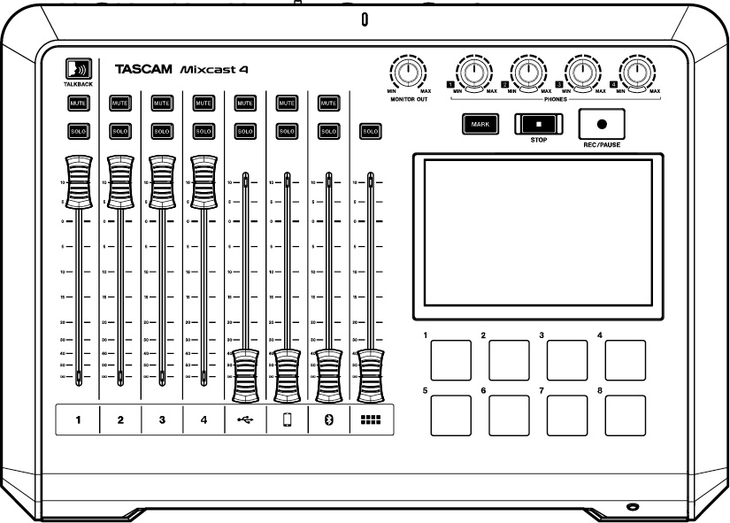
Top panel
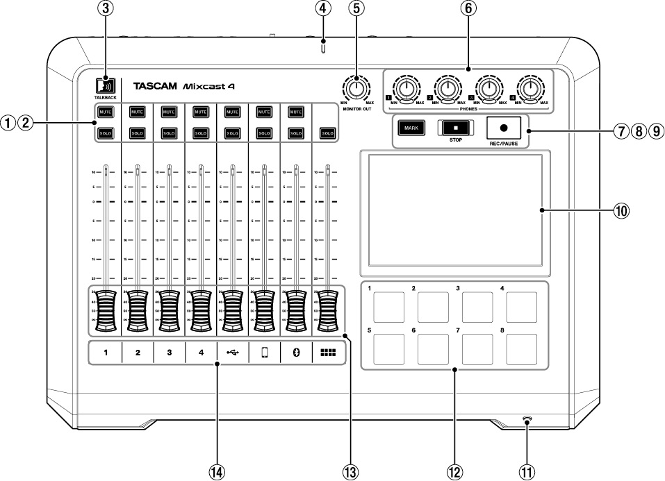
 MUTE buttons
Pressing a MUTE button mutes (silences) the signal input on that channel.
These light red when on. SOLO buttons
Pressing a SOLO button enables the signal input on that channel to be monitored by itself through the PHONES 1 jack on the back or the PHONES (TRRS)  jack on the front. (This does not affect recording.)
These light blue when on. TALKBACK button
While this button is being pressed, the signal input through MIC INPUT 1 is output through the PHONES 2–4 jacks on the back.
(This sound will not be recorded when recording.)
This button lights blue while being pressed. Recording indicator
This lights red while recording. MONITOR OUT knob
Use this to adjust the output of the MONITOR OUT and LINE OUT jacks on the back.
 PHONES
  -
-  knobs
knobs
Connect these to the PHONES  -
-  jacks on the back or the PHONES (TRRS)
  jack on the front.
 MARK button
When playing, recording or paused, press this button to add a mark at the current point.
This lights blue during playback/recording as well as when playback/recording is paused. STOP button
Press this to stop playback or recording.
This lights orange during playback and recording as well as when recording is paused. REC/PAUSE button
Press this to start recording. When recording, press this to pause.
This lights red while recording and blinks red when recording is paused. Touchscreen
This allows input signals to be monitored and shows the operation status of the unit. Various settings can be made by touch operation.
(See "Touchscreen Functions".)
 PHONES (TRRS)
  jack (CTIA standard)
Connect a headset, for example, here.
A headset mic can be input on channel 1 using a menu setting. (CTIA standard)
(See "Connecting headsets (switching Mic 1 input)".)
 SOUND PAD buttons (1-8)
This allows input signals to be monitored and shows the operation status of the unit. Use the TASCAM Podcast Editor software to set the audio sources.
 Channel faders
Use these to adjust the send levels of channel signals.
 Channel indicators
The channel LEDs light red when input overloads are detected. (Adjust input levels if they light frequently.)|
1/2/3/4 |
MIC INPUT 1-4 input signals |
|
|
USB input signals |
|
|
LINE IN L/R or LINE IN (TRRS) input signals |
|
|
Bluetooth input signals |
|
|
Sound pad playback sounds |
Rear panel
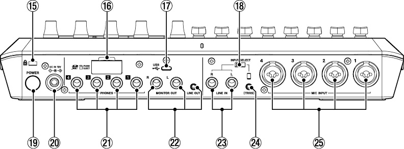
 Kensington Security Slot
 SD card slot
Use this slot to insert SD cards.
 USB port (Type-C)
This is a USB Type-C port. (This supports USB 2.0.)
Use this to connect a computer, smartphone or tablet.
(See "Making USB connections".)
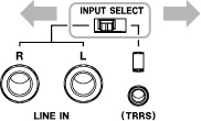
 INPUT SELECT switch
Use this to switch between the LINE IN L/R and LINE IN (TRRS) inputs.
 POWER button
Press this to turn the unit on and off.
(See "Turning the power on and off".)
 DC IN 12V connector
Connect the included AC adapter (PS-P1220E NUT) here.
 PHONES
  -
-  jacks
jacks
Use these standard 6.3mm stereo jacks to connect headphones.
Use adapters (3.5mm stereo mini jack) to connect headphones with mini plugs.
(See "Connecting headphones".)
CAUTION
Before connecting headphones, minimize the volumes with the PHONES  –
– knobs (). Failure to do so might cause sudden loud noises, which could harm your hearing or result in other trouble.
 MONITOR OUT L/R and LINE OUT jacks
Connect monitor speakers (powered speakers or an amplifier and speaker system) to the SUB OUTPUT L/R jacks.
Use the MONITOR OUT knob () on the top to adjust the output levels.
MONITOR OUT L/R jacksConnectors: 6.3mm (1/4") standard TRS jacks
LINE OUT jackConnector: 3.5mm (1/8") stereo mini jack
(See "Connecting recording devices and monitor speakers".)
CAUTION
Before turning the power on and connecting monitor speakers, minimize the volume with the MONITOR OUT knob () on the top. Failure to do so might cause sudden loud noises, which could harm your hearing or result in other trouble.
 LINE IN L/R jacks
Connect a media player or other audio device here.
Set the INPUT SELECT switch to the LINE IN side to use these.Connectors: 6.3mm (1/4") standard TRS jacks
(See "Connecting smartphones, media players and similar devices".)
 LINE IN (TRRS) jack (CTIA standard)
Connect a smartphone or other portable device here.
Set the INPUT SELECT switch () to  . (CTIA standard)
Connector: 3.5 mm (1/8") 4-pole mini jack
(See "Connecting smartphones, media players and similar devices".)
 MIC INPUT 1-4 jacks
Connect dynamic and condenser mics to these.
(For mic connection and mic type selection, See "Connecting microphones" and See "Mic settings".)
CAUTION
When “Condenser” is selected for a MIC INPUT jack in the mic settings, phantom power (+48V) will be turned on. Doing so could damage dynamic mics if they are connected.
Be careful when connecting mics and selecting mic types.
Home Screen
When the unit is turned on, the Home Screen appears on the touchscreen as shown below.
As a rule, touchscreen operations are either touching an icon with a finger (hereafter, “tap”) or moving left/right on the screen (hereafter, “swipe”). (If the response to fingers is poor, operation using a stylus designed for smartphones and tablets is also possible.)
This screen allows input signal levels to be monitored and shows the operation status of the unit. In addition, various function settings can be accessed by tapping the Menu icon on the screen.
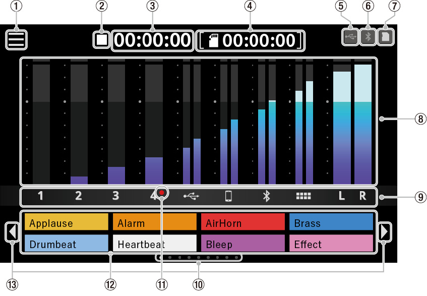
Menu icon
Tap this icon to open the Menu Screen.
Recorder operation status
This icon shows the recorder operation status.
|
Indicator |
Meaning |
|
|
Stop |
|
|
Recording |
|
|
Recording paused |
Recording counter
This shows the current elapsed time (in hours: minutes: seconds) when recording.
SD counter
This shows the remaining time available for recording on the SD card (in hours: minutes: seconds).
USB icon
The  icon appears when connected by USB.
Bluetooth icon
The  icon appears when a Bluetooth device is connected.
The  icon blinks when waiting to pair.
SD card icon
When an SD card is loaded, the  icon appears.
Level meters
These show the levels of the channels.
|
1 - 4, |
Levels sent to the stereo mix |
|
L/R |
Stereo mix levels |
Input channel identifiers
|
Indicator |
Corresponding input jacks |
|
1 – 4 |
MIC INPUT 1-4 jacks |
|
|
USB port |
|
|
LINE IN (TRRS) jack |
|
|
Bluetooth input |
|
|
Sound pads |
|
L/R |
2MIX |
SOUND PAD bank indicator
The position of the SOUND PAD bank currently shown is highlighted.
Condenser mic selected indicator
Red dots will be shown next to mic channel numbers set to “Condenser” in the mic settings.
Sound Pad display
These show the names of the audio files that have been assigned to the Sound Pads.*
Use the dedicated software to set audio sources.
*Pre-assigned effect sounds (included audio sources) are set for the Bank 0 Sound Pads.
SOUND PAD bank switch(  /
/  ) icons
Tap the  icon to switch to the lower bank. Tap the
icon to switch to the higher bank.
Making connections
Connecting audio equipment
The following is an example of connections with this unit.
Precautions before making connections
Carefully read the operation manuals of the devices to be connected and then connect them correctly. Before making connections, turn this unit and all equipment to be connected off (standby). Install all connected devices, including this unit, so that they are powered from the same line. When using a power strip or similar device, be sure to use one that has high current capacity (thick cable) in order to minimize fluctuations in power voltage. CAUTION
Before turning the power on or connecting audio equipment, set the following knobs and faders on this unit and the knobs and faders of the devices being connected to their lowest values. Failure to do so could cause sudden loud noises from monitoring equipment, and this could damage the equipment or harm hearing.
Channel faders (), PHONES  –
–  knobs (), MONITOR OUT knob ()
|
Connection example |
|
|
|
Back |
|
|
|
Front |
Note: For details about – in the illustration above, See "Top panel" and See "Rear panel".
Connecting the power
Use the included AC adapter (PS-P1220E NUT) to connect a power supply to the unit as shown below.
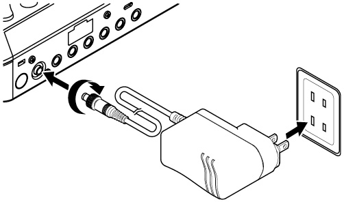
CAUTION
Always connect the included AC adapter (PS-P1220E NUT), which is specified for use with this unit.
Use of a different adapter could cause malfunction, fire or electric shock.
Turning the power on and off
Turning the power on
) on the back to turn the unit on.|
|
|
POWER button ( |
NOTE
A tutorial that explains the unit simply will appear the first time it is turned on after purchase. Then, the Others Screen will open on the touchscreen so that language and Date/Time settings can be made.
(For language, date and time setting instructions, see "Date/ Time Adjust" in See "Other settings".)
|
|
|
Home Screen |
Turning the power off
Press and hold the POWER button () to turn the unit off.
When a pop-up message appears on the touchscreen to confirm turning the power off, release the POWER button.

Tap “Yes” to run the shutdown procedure and turn the unit off.
NOTE
The unit will save various settings before it turns off. This unit has an AUTO POWER OFF function that can automatically turn it off.For details about the AUTO POWER OFF function, see the corresponding section in See "AUTO POWER OFF".
Tutorial overview
When the unit is turned on, a tutorial screen will open to explain the basics of operating the unit. If the tutorial is unnecessary, tap the × at the top right to close the screen. Put a check in the “Hide Tutorial” checkbox in the final tutorial screen to prevent it from being shown in the future.**This tutorial will be shown again if the unit is restored to its default settings.
(To restore the unit to its default settings, in See "Other settings".)
Connecting microphones
Tap the  input icon on the Menu Screen to open the Input Screen
|
|
|
Menu Screen |
 –
–  mic icon to select that mic.
|
|
|
Input Screen |
(The following illustration example shows “Mic1”.)
|
|
|
Level Screen |
Only the Mic 1 screen has “Front” and “Rear” options.After selecting the mic type, tap the  home icon at the top right to return to the Home Screen.
If “Condenser” is selected as the mic setting, +48V power will be supplied to that mic input and a red dot will be shown next to that channel number on the Home Screen.
|
|
|
Home Screen |
CAUTION
Do not connect mics that are compatible with plug-in power. When “Condenser” is selected as the mic setting for a MIC INPUT jack, phantom power (+48V) will be turned on. Doing so could damage dynamic mics if they are connected.Be careful when connecting mics and selecting mic types.
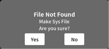
If “Condenser” has been selected, the following message will appear the next time the unit is turned on.
Tap “Yes” to supply phantom power (+48V) to mic inputs that have been set to “Condenser”.
Tap “No” to change the settings of all mic inputs to “Dynamic”.
Connecting headphones
Connect headphones to the PHONES  –
–  jacks () on the back.
CAUTION
Before connecting headphones, minimize the volumes with the PHONES  –
–  knobs (). Failure to do so might cause sudden loud noises from the headphones, which could harm hearing or result in other trouble.
Connecting headsets (switching Mic 1 input)
Connect a headset to the PHONES (TRRS)
jack () on the front.
CAUTION
Before connecting a headset, minimize the level of the PHONES  knob () on the top.
Failure to do so might cause sudden loud noises from the headset, which could harm hearing or result in other trouble.
Using a headset mic
To use the headset mic input as channel 1, set the input to “Front” on the Mic 1 Level Screen.
|
|
|
Level Screen |
To use the MIC INPUT 1 jack () on the back of the unit set the input to “Rear” (default) on the Mic 1 Level Screen.NOTE
Output volume could be reduced if both PHONES  jacks () and PHONES (TRRS)
jack () are used at the same time.
Making USB connections
Using USB to connect a computer, smartphone or tablet makes the following possible.
The SD card in this unit can be used as USB mass storage. Audio can be input and output by using it as a USB audio device.) on the back of this unit and to a computer, smartphone or tablet. USB icon will appear at the top right of its Home Screen.
NOTE
The unit should be connected using the included USB cable* directly to the smartphone, tablet or computer, not through a USB hub.
*When using a USB cable purchased elsewhere, use a high-quality cable (that has USB certification) of the shortest length possible. (See "USB cables".)
Connecting smartphones, media players and similar devices
Connect smartphones and other portable devices as well as media players and other audio devices to the LINE IN (TRRS) or LINE IN jacks on the back of the unit. Doing so allows input of these sound sources.
Audio from a caller can be input by connecting a mobile phone or smartphone to the LINE IN (TRRS) jack of this unit. Likewise, audio from this unit can also be sent to the caller.NOTE
The Mix Minus function is always used on audio output through the LINE IN (TRRS) jack. This prevents the audio from callers being returned to them.
) on the back of the unit according to the type of device being input. When connecting a smartphone or other portable device to the LINE IN (TRRS) jack ()Set the INPUT SELECT switch () to  (TRRS)
When connecting a media player or other audio device to the LINE IN L/R jacks ()Set the INPUT SELECT switch () to LINE IN
 input icon on the Menu Screen to open the Input Screen. Then, tap the
  smartphone icon to make voice settings, referring to See "Smartphone settings".
|
|
|
Input Screen |
Connecting recording devices and monitor speakers
Sound mixed or played back on this unit can be output through the MONITOR OUT L/R jacks () or LINE OUT jack () on its back to monitor speakers (powered monitor speakers or an amp and speaker system).
MONITOR OUT L/R jacks ()For example, connect a recording device or powered monitor speakers that are compatible with standard 6.3mm (1/4") TRS jacks.
LINE OUT jack ()For example, connect these to input connectors that support line input on a recording device.
Use the MONITOR OUT knob on the top to adjust the speaker volume.
NOTE
If the volume cannot be adjusted with the MONITOR OUT knob (), confirm that “Line Level Output” is set to “OFF” in the See "8-5-1. AUDIO" on page 36.
Volume cannot be adjusted when set to “ON”.
CAUTION
Before turning the power on and connecting monitor speakers, minimize the volume with the MONITOR OUT knob () on the top. Failure to do so might cause sudden loud noises, which could harm your hearing or result in other trouble.
Connecting with Bluetooth devices
This unit has a built-in Bluetooth audio module. This enables input of sound played on computers and portable audio devices that support Bluetooth (A2DP) as well as output of sound from this unit to other Bluetooth devices.
Audio from a caller can be input by connecting a smartphone to this unit by Bluetooth. Likewise, audio from this unit can also be sent to the caller.
NOTE
The Mix Minus function is always used on audio output to Bluetooth devices. This prevents the audio from callers being returned to them.
Pairing
Follow the procedures below to enable pairing with a Bluetooth device.
NOTE
Pairing also requires operation of the Bluetooth device.
Refer to the operation manual of the Bluetooth device being used for instructions about how to use it.
 input icon on the Menu Screen to open the Input Screen. Then, tap the
  Bluetooth icon.
|
|
|
Input Screen |
|
|
|
Level Screen |
NOTE
After the unit is turned on, the unit will automatically activate pairing mode for some time. Then, it will deactivate pairing mode.
|
|
|
Level Screen |
NOTE
If connecting does not complete after some time, pairing mode will be deactivated automatically. To reactivate pairing mode, tap the “Pairing” button again.
 Bluetooth icon will appear at the top right of the Home Screen.
SD card insertion, removal and write protection
Loading SD cards
This unit uses SD cards for recording and playback.
This unit can use SD cards that are Class 10 or higher and compatible with SD, SDHC or SDXC standards.
NOTE
This product does not include an SD card.Please purchase any that you need for your uses.
We recommend using SD cards with capacities of at least 64 GB because multitrack recordings of all channel inputs use large amounts of space. A list of SD cards that have been confirmed for use with this unit can be found by accessing the TEAC Global Site (https://teac-global.com).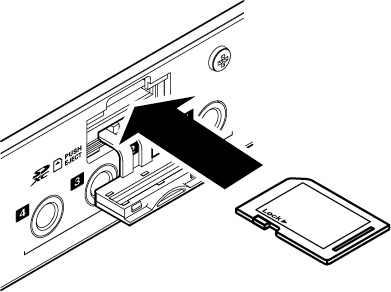
 SD card icon will appear at the top right of the Home Screen.
NOTE
SD cards formatted by this unit are optimized to improve performance during recording. Use this unit to format the SD cards to be used with it.
Errors might occur when recording with this unit using an SD card formatted by a computer or other device.
Removing SD cards
First, turn the unit off or stop operation. Then, gently press the SD card in to eject it, and remove it
CAUTION
Never remove an SD card when the unit is operating (including recording, playing back, or writing data to the SD card).
Doing so could cause proper recording to fail, data to be lost, and sudden loud noises from monitoring equipment, which might damage the equipment, harm hearing or cause other trouble.
) on the back and push the card in gently until it comes out. SD card icon at the top right of the touchscreen will disappear.
SD card write protection switches
SD cards have write-protection switches that prevent writing new data to them.
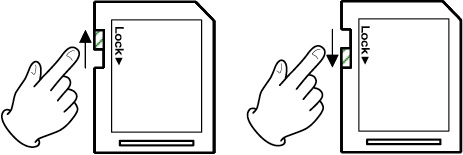
If you slide the write-protection switch to the “LOCK” position, writing will not be possible. Move the write-protection switch to the unlocked position in order to record, erase and otherwise edit data on the card.
Adjusting input levels, audio characteristics and effects
Adjust each input before starting recordings for podcasts.
Adjust the input levels, audio characteristics and effects to prevent distortion by input volumes that are too high or inaudible recording by levels that are too low.
Lowering knob and fader volumes
Before starting input adjustments, set the following knobs and faders on this unit and the knobs and faders of the devices being connected to their lowest values.
Lower channel faders ().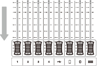
Lower the MONITOR OUT () and PHONES  – ) knobs.
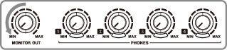
Selecting mics for adjustment
 menu icon on the Home Screen to open the Menu Screen.
|
|
|
Home Screen |
 input icon.
|
|
|
Menu Screen |
 –
–  mic icon for the mic input to adjust.
|
|
|
Input Screen |
|
|
|
Level Screen |
Adjusting mic input levels
This is an example of procedures to adjust MIC INPUT 1.
|
|
|
Level adjustment |
) knob.Adjusting mic input audio characteristics (Voice Setting)
After adjusting the volume peak, adjust the mic input audio characteristics as desired.
|
|
|
Voice Setting selection screen |
The Voice Setting Screen has two pages.
|
|
|
Voice Setting Screen page 1 |
Tap the [<] and [>] buttons at the bottom of the Voice Setting screen to switch between the two pages.
Adjusting the Tone
Tap the Tone switch to turn it on.
Three presets can be selected for Tone. Select Manual to make adjustments instead of using a preset.
|
|
|
Voice Setting Screen page 1 (MIC INPUT 1 jack example) |
Tapping one of the Tone setting icons selects it, highlighting it and turning the function on.
|
Deep |
This emphasizes low frequencies, making the tone deep. |
|
Mid (default) |
This emphasizes middle frequencies. |
|
Bright |
This emphasizes high frequencies, making the tone bright. |
|
Manual |
This allows detailed tone adjustments. Tap the Manual icon to show the
|
Tap the  settings icon to open the Tone Manual Setting Screen. See "Tone Manual settings".
Adjusting the Compressor
|
|
|
Voice Setting Screen page 1 (MIC INPUT 1 jack example) |
Tap the Compressor switch to turn it on.
Two presets can be selected for the Compressor.
Select Manual to make adjustments instead of using a preset.
Tapping one of the Compressor setting icons selects it, highlighting it and turning the function on.
|
Soft (default) |
This naturally compresses loud parts of the sound. |
|
Hard |
This greatly compresses everything to even the level. |
|
Manual |
This allows detailed compressor adjustments. Tap the Manual icon to show the
|
Tap the  settings icon to open the Compressor Manual Setting Screen. See "Compressor Manual settings".
Adjusting the Processing
|
|
|
Voice Setting Screen page 2 (MIC INPUT 1 jack example) |
Tap the Processing switch to turn it on.
Tapping one of the Processing setting icons selects it, highlighting it and turning the function on.
|
De-esser |
Reduce harsh high-frequency sibilant sounds. |
|
Noise Suppressor |
Reduce background noise. |
|
Ducking* |
When a signal is input through MIC INPUT 1, other signal levels will be lowered, making the sound from MIC INPUT 1 stand out. |
*The Ducking setting can only be used with MIC INPUT 1.
The  settings icons will be shown when processing setting functions are on.
Tap a  settings icon to enable detailed settings.
See De-esser manual settings (mic input) for details about De-esser manual settings. See Noise suppressor settings (mic input) for details about Noise Suppressor settings. See Ducking manual settings (mic input) for details about Ducking manual settings.Adjusting mic input effects (Effect Setting)
The following adjustments can be made to change the mic input sound as desired.
The effect function is linked to the Sound Pad buttons ().
By assigning an effect to a pad, its settings can be applied while the pad is pressed.
The effect can only be turned on for one channel.
NOTE
The effect functions that can be assigned to Sound Pads () are “Reverb” and “Voice Changer”.
|
|
|
Effect Setting selection screen |
A confirmation message will appear. Tap “OK” to open the Effect Setting Screen.
The Effect Setting Screen has two pages.
|
|
|
Effect Setting Screen page 1 |
Tap the [<] and [>] buttons at the bottom of the Effect Setting Screen to switch between the first and second pages.
The following settings can be made on the first page of the Effect Setting Screen.
Reverb adjustment
Use the Reverb function to adjust the reverberations and make related settings.
|
|
|
Effect Setting Screen page 1 |
A confirmation message will appear when the reverb switch is turned on. Tap “OK” to turn on the Reverb function.
The following three presets can be selected for Reverb. Select Manual to make adjustments instead of using a preset. Tapping one of the Reverb setting icons selects it, highlighting it and activating that setting.|
Small |
This is equivalent to the “Room” manual reverb setting and has the smallest amounts of reflections and reverb sound. |
|
Medium (default) |
This is equivalent to the “Studio” manual reverb setting and has medium amounts of reflections and reverb sound. |
|
Large |
This is equivalent to the “Hall” manual reverb setting and has the greatest amount of reflections and reverb sound. |
|
DRY/WET |
Move the slider to adjust the amount of the reverb effect. |
|
Manual |
This allows detailed reverb adjustments. Tap the Manual icon to show the
Tapping another icon will make the |
Tap the  settings icon to open the Reverb Manual Setting Screen.
The following settings can be made on the second page of the Effect Setting Screen.
Adjusting the Voice Changer
The Voice Changer function can make voices sound lower or higher by adjusting the pitch.
|
|
|
Effect Setting Screen page 2 |
Turn the Voice Changer switch on to enable the Voice Changer function.
Move the slider or use the [-] and [+] buttons to adjust the pitch.
As necessary, tap the  input icon on the Menu Screen to open the Input Screen, and make the following input adjustments and settings.
|
|
|
Input Screen |
USB settings (see 8-2-2. USB settings) Smartphone settings (see 8-2-3. Smartphone settings) Bluetooth settings (see 8-2-4. Bluetooth settings)Recording
Start podcast recording after completing adjusting the input levels, audio characteristics and effects for each channel.
See "Adding effect sounds while recording" for procedures to switch banks. See "Sound Pad overview" for procedures to add effect sounds and BGM to Sound Pads.NOTE
The Sound Pad bank cannot be changed while recording.
 ] button () on the unit to start recording.
|
|
|
Recording Home Screen |
Press the REC/PAUSE [] button () while recording to pause recording.(The  paused icon will appear when recording is paused.)
|
|
|
Screen when recording is paused |
 ] button () when recording or paused.
The following message will appear.

NOTE
Recording will continue while the message is shown until “Yes” is tapped.
The provisional name will be shown. Use the screen keyboard as necessary to input a new name for the podcast, and tap “OK”.
|
|
|
RENAME Screen |
NOTE
Tap “Aa” on the keyboard to switch between uppercase letters, lowercase letters, and numbers and symbols. If wrong characters are input, tap “Del” to delete one character at a time. Podcast files are saved in the PODCAST folder on the SD card. Saved files are named with the podcast name and “_01.wav” added to the end.If the file size exceeds 4 GB, additional files will be created and named in order with “_02.wav” and “_03.wav” added to their ends.
NOTE
When SD Multi Record is ON, recording to files will occur with the following channel order.|
Channels 1/2/3/4 |
MIC INPUT 1-4 input signals |
|
Channels 5/6 |
USB input signals |
|
Channels 7/8 |
LINE IN L/R or LINE IN (TRRS) input signals |
|
Channels 9/10 |
Bluetooth input signals |
|
Channels 11/12 |
Sound pad playback sounds |
|
Channels 13/14 |
Stereo mix |
When SD Multi Record is off, only the stereo mix will be recorded.Adding effect sounds while recording
Effect sounds and BGM assigned to Sound Pads can be added while recording.
 and
and  icons to switch banks to open the one with the Sound Pads that have the necessary sounds.
|
|
|
Home Screen (switching banks) |
) to play the sounds assigned to them.NOTE
Playing effect sounds and BGM while recording will cause those sounds to also be recorded. The bank cannot be changed while recording. Switch to the necessary bank before beginning recording.Adding marks while recording
Press the MARK button () while recording at positions where events occur to add marks at those points.
This is useful to check content if you want to change it after recording.

The necessary points can be found quickly when editing recorded content in the dedicated software or to overwrite it on the Advanced Screen opened from the PLAY Screen.
Added marks can be checked on the Advanced Screen during playback.
(See "Checking added marks on the Advanced Screen".)
NOTE
The maximum number of marks that can be added to a single podcast is 99.
Playing recordings
This unit can play podcasts recorded on it.
 menu icon on the Home Screen to open the Menu Screen.
|
|
|
Home Screen |
 play icon.
|
|
|
Menu Screen |
This opens the podcast PLAY Screen.
|
|
|
PLAY Screen |
The selected podcast will be highlighted.
 play icon to start playback.
Press the MARK button () while it is lit to add a mark at that point.
(See "Adding marks during playback".)
play icon will change to the pause icon.Tap the pause icon to pause playback.
When paused, it changes to the play icon. Tap the play icon again to resume playback.|
|
|
Screen when stopped |
Press the STOP [] button () when paused to set the playback starting position to the beginning of the podcast. Selecting a different podcast or opening any screen other than the PLAY Screen will stop playback of the podcast.Changing the names of podcasts
Podcast names can be changed using the following procedure.
|
|
|
PLAY Screen |
The selected podcast will be highlighted. rename icon to open the RENAME Screen.
Use the screen keyboard to input a new name for the podcast.
|
|
|
RENAME Screen |
Tap “Aa” on the keyboard to switch between uppercase letters, lowercase letters, and numbers and symbols. If wrong characters are input, tap “Del” to delete one character at a time.Deleting podcasts
|
|
|
PLAY Screen |
 trash icon to open the following message.
Tap “OK” to delete the podcast.
ATTENTION
Deleted podcasts cannot be restored.
Be careful not to use this function mistakenly in order to avoid deleting important data.
Adding marks during playback
By adding marks, points can be found quickly when editing recorded content in the dedicated software or overwriting on the Advanced Screen.
Press the MARK button () during playback to add marks at positions where you want them.
The following message will appear when marks are added.
Added marks can be checked on the Advanced Screen.
Advanced playback functions
Using advanced playback functions, podcasts can be recorded over and checked. On the Playback Screen, tap the Advanced button.
|
|
|
PLAY Screen |
|
|
|
Advanced Screen |
 Play icon
Tap this to play the selected podcast. During playback, the  play icon will change to the pause icon.
 Timeline and slider
The playback position can be changed as desired by moving the slider on the timeline.
 Time jumping controls
Tap the time display field to show and select from the following forward/backward jump times.
1s, 5s, 10s (default), 30sAfter selecting the jump time, tap the  and
and  icons to find the position where overwriting should start.
 SET button
Tap this to move the mark (overwrite starting position) to the slider position.
 CLEAR button
This clears the mark (overwrite starting position) shown by the SET button.
 Mark jump controls
When playing a podcast that already has marks added to it, tap the  and
and  icons to move the slider directly to them on the timeline.
Checking added marks on the Advanced Screen
Added marks can be checked on the Advanced Screen.
Tap the Advanced button to open the Advanced Screen.
|
|
|
PLAY Screen |
If a podcast has marks added to it, they will be shown above the timeline.|
|
|
Advanced Screen |
Tap the  and
and  jump icons to move the slider directly to marks on the timeline.
|
|
|
Advanced Screen |
Deleting added marks on the Advanced Screen
To delete a mark that has been added, when playback is stopped or paused, use the  and
and  mark jump icons to move the slider to the desired mark. Then, press the MARK button () to delete it
|
|
|
Advanced Screen |
The following message will appear when marks are deleted.

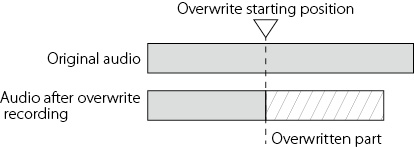
Overwrite recording
A recorded podcast can be recorded over (overwritten) from a mark point added to it or any desired position using the advanced playback functions.
When overwrite recording is conducted, from the time where it starts, the existing audio will be replaced with the new recording.
Overwrite recording from an added mark
Select the podcast to overwrite on the PLAY Screen, and tap the Advanced button to open the Advanced Screen.
 and
and  MARK jump controls to move the slider on the timeline to the point where you want overwrite recording to start. Then, tap the SET button.
|
|
|
Advanced Screen |
This will set the recording starting position, which will be shown as the Overwrite Position mark above the timeline.
|
|
|
Advanced Screen |
NOTE
The overwrite recording starting position will be set after 00:00:01.
] button () on the unit to start overwrite recording. While overwriting, the Overwrite Recording Home Screen will be shown.|
|
|
Overwrite Recording Home Screen |
] button ().The following message will appear.
|
|
|
|
|
Advanced Screen |
play icon on the confirmation screen to check the content of the overwritten recording. If there are no issues, tap “OK”. Tap “Retry” if you want to redo overwrite recording. Since this will open the confirmation message in step 2, press the REC/PAUSE [] button (). To cancel overwriting, tap “DISCARD”.Using TALKBACK functions
By using the TALKBACK function, speaking (from the director) through Mic 1 can be output only to PHONES  –
–  (the participants) during podcast recording, for example.

To use the TALKBACK function, speak through Mic 1 while pressing the TALKBACK button ().While the TALKBACK button () is being pressed, output is through the PHONES  –
–  jacks.
Furthermore, unless the SOLO function is being used, it will also be output through the PHONES  and PHONES (TRRS)
  jacks.
While the TALKBACK button () is being pressed, the Mic 1 input audio will be muted and not recorded. It will not be output from the MONITOR OUT L/R or LINE OUT jacks ().This unit can be used with the functions of a 14-in/2-out USB audio interface by connecting it to a computer, smartphone or tablet by USB.
In addition, the dedicated software* can be used to add effect sounds, background music and other sounds to the Sound Pads as well as to edit podcasts recorded on the unit.
Note: See the TASCAM Podcast Editor operation manual for details about the software.
Sound settings when using with Windows OS
Confirm that a check ( ) is next to “Mic (Mixcast 4)”, and click “Properties (P)”.
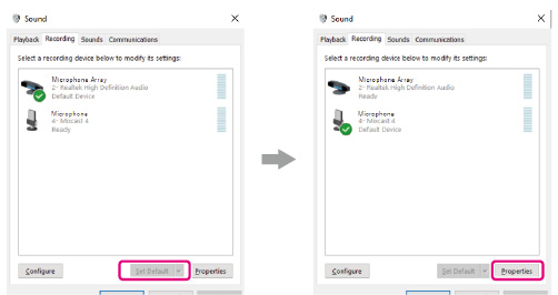
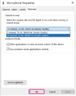
To use TASCAM Podcast Editor or other software that supports multiple channels, select a 14 channel setting. Select a 2-channel setting when using OBS Studio or another application that supports 2-channel audio devices.This completes Windows OS sound settings.
NOTE
By installing a dedicated ASIO driver when using Windows OS, it can also be used with ordinary DAW software that supports ASIO. The dedicated ASIO driver can be downloaded from the website for this product.
Using with Mac OS (audio settings)
 ) app from the Applications folder.
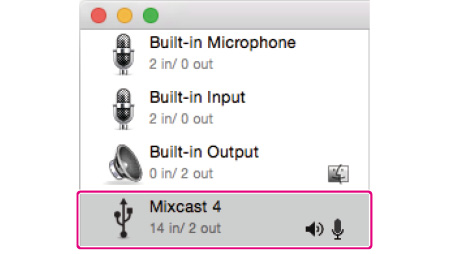
Do not enable “Play Alerts and Sound Effects Through This Device”.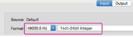
This completes making audio settings for Mac OS.
Using with iOS/iPadOS devices
No sound or audio settings are necessary for connecting and using with iOS and iPadOS devices.
Data output by USB
Data output from this unit will be input to the computer, smartphone or tablet with the following channel order.
For Windows OS, Mac OS, iOS and iPadOS
|
Channels 1/2 |
Stereo mix |
|
Channels 3/4/5/6 |
MIC INPUT 1-4 input signals |
|
Channels 7/8 |
USB input signals |
|
Channels 9/10 |
LINE IN L/R or LINE IN (TRRS) input signals |
|
Channels 11/12 |
Bluetooth input signals |
|
Channels 13/14 |
Sound pad playback sounds |
Sound Pad overview
Effect sounds, background music (BGM) and other audio can be assigned to each of the Sound Pads () on top of the unit. Groups of sound source settings for pad buttons (1–8) are called “banks” in this document. This unit can switch between 9 banks (0–8), allowing a total of 72 different sounds to be played. Up to 8 sounds can be set for the pads in banks 1–8. Bank 0 is preset with sound sources included in the unit.Press the pads to play the sounds assigned to them.
During recording, assigned sounds can be played and various effects can be applied to the recording.
Using the dedicated software, sounds can be transferred to each pad. (See the TASCAM Podcast Editor operation manual for details about the software.) Use the Pad Settings on the Sound Pad Settings Screen to edit the function assignments of each pad (including color, play method and setting clearing). Using PAD Advanced on the Sound Pad Settings Screen, a “Bleep” sound or effect can be set.*The mic effect setting can be assigned to a sound pad and applied.
(See "Adjusting mic input effects (Effect Setting)".)
Using PAD Rec in the Sound Pad settings, recorded sounds and effect sounds can be assigned to each pad.Explanation of Sound Pad Screen functions
Tap the  menu icon on the Home Screen to open the Menu Screen. Then, tap the
  sound pad icon to open the Sound Pad Screen.
|
|
|
Sound Pad Screen |
Pads
Tap a pad to check or change the function assigned to it. These are linked to the Sound Pad buttons on the unit ().
Sound Pad Bank indicators
The number of the currently selected bank is highlighted.
Sound Pad Bank switch icons
Tap the  icon to switch to the lower-numbered bank.
Tap the  icon to switch to the higher-numbered bank.
Pad color setting
The color of the selected pad can be changed.
Trash icon
Tap this icon to clear the settings and functions assigned to the selected pad.
Play Method
This shows how the effect sound or BGM of the selected pad will be output.
The output mode can also be selected and changed.
Tap the button and select one of the following play methods.
|
Latch |
Press once to start playback, and once again to stop it. Press again to play from the beginning. If nothing is done, the file will play to its end before stopping. |
|
Pause |
Press once to start playback, and once again to pause. Press again to resume playback. If nothing is done, the file will play to its end before stopping. |
|
RePlay |
Press once to start playback. Press again to restart playback from the beginning. If nothing is done, the file will play to its end before stopping. |
|
One Shot |
Press once to start playback. The file will play to its end. To stop during playback, press and hold the pad button. |
|
Repeat |
Press once to start playback, and once again to stop it. Press again to play from the beginning. If nothing is done, the file will play repeatedly. |
|
Touch |
The sound will play only while the pad is being pressed. |
Sound source file name
This shows the name of the sound source file shown on the pad.
PAD Settings
The desired color can be selected and set with the pad color setting (). These colors are also applied the Sound Pad buttons on the unit (). How effects and BGM are output can be set with the Play Method button (). PAD Rec
Effect sounds and BGM can be captured from each input signal.
(See "Recording sounds and assigning them to Sound Pads".)
PAD Advanced
Apply mic effect settings.
(See "Assigning effects to Sound Pads".)
Playing Sound Pads
Sound Pads can be played on the Home Screen and MENU Screen.
NOTE
Sound Pads cannot be used during podcast playback on the PLAY Screen or Advanced Screen.
) to check their playback sounds|
|
|
Pad playback |
) to adjust playback levels.|
|
|
Fader adjustment |
Assigning effects to Sound Pads
Mic input sounds can be changed by effects assigned to Sound Pads.
As an example, here we explain the procedure to add a sound that uses the voice changer effect function to Pad 1 of Bank 1.
This effect will be applied when the pad is pressed.
(See "Adjusting mic input effects (Effect Setting)".)
|
|
|
Sound Pad Screen PAD Settings page |
NOTE
Since Bank 0 is preset with the sound sources included in the unit, select Bank 1–8. If the pad in the bank you want to add the effect to already has an assignment, tap the  trash icon and clear that pad, or tap a different pad that is empty.
|
|
|
Sound Pad Screen PAD Settings page |
The desired color can be set.
|
|
|
Sound Pad Screen PAD Settings page |
“Effect” will be shown on Bank 1 Pad 1.
|
|
|
Advanced functions on Sound Pad Screen |
This adds the effect function to Pad 1 of Bank 1.
NOTE
The only playback method for the bleep sound is Touch. The only playback methods for the effect are Latch and Touch.|
|
|
Advanced functions on Sound Pad Screen |
 Home icon at the top right to return to the Home Screen
|
|
|
Sound Pad Screen PAD Settings page |
) button 1.The effect will be applied to the mic input while the button is being pressed
|
|
|
Home Screen |
Clearing Sound Pad effect functions
Use the following procedures to clear effect functions assigned to Sound Pads.
As an example, here we explain the procedure to remove an effect function assigned to Bank 1.
|
|
|
Sound Pad Screen PAD Settings page |
|
|
|
Sound Pad Screen PAD Settings page |
“Effect” is shown in the audio source file name field. Tap the  garbage icon to clear the assigned effect function.
Recording sounds and assigning them to Sound Pads
Sound Pad audio sources can be recorded by this unit.
(The stereo mix of the unit is recorded.)
As an example, here we explain the procedure for recording and adding a sound to Pad 1 of Bank 1.
|
|
|
Sound Pad Screen PAD Settings page |
|
|
|
Sound Pad Screen PAD Settings page |
The desired color can be set. As necessary, select the Play Method on the Sound Pad Screen to set how it plays back.|
|
|
Sound Pad Screen PAD Settings page |
Rec Start” button to start recording.|
|
|
Sound Pad Screen ready to record |
Rec Stop”.|
|
|
Sound Pad Screen ready to stop recording |
Rec Stop” button to stop recording.The provisional name will be shown. Use the screen keyboard as necessary to input a new name.
|
|
|
RENAME Screen |
|
|
|
Sound Pad Screen ready to record |
This completes assigning the recorded sound to Pad 1 of Bank 1.
|
|
|
Sound Pad Screen ready to record |
 Home icon at the top right to return to the Home Screen
|
|
|
Sound Pad Screen PAD Settings page |
) button 1 to play the sound recorded using the Sound Pad Screen recording function.|
|
|
Home Screen |
NOTE
If the playback sound cannot be heard, adjust the Sound Pad fader.
Tap the Menu icon on the Home Screen to open the Menu Screen.
Tap the icons on this screen to access the operations and settings of various functions.
 Menu icon on the Home Screen to open the Menu Screen.
|
|
|
Home Screen |
|
|
|
Menu Screen |
< icon
Tap this icon to return to the screen that was open before this one.
Function name
This shows the function name of the screen being shown.
Function icons
 Inputs
This opens the Input Screen (8-2. Input selection).
 Playback
This opens the podcast PLAY Screen (8-3. Playback settings).
 Sound Pads
This opens the Sound Pad Settings Screen (8-4. Sound pad settings).
 Hardware Settings
This opens the Hardware Settings Screen for the unit (8-5. Hardware Settings).
 SD Settings
This opens the settings screen for SD cards (8-6. SD Settings).
Home icon 
Tap this icon to open the Home Screen.
Tap the  Input icon to open the Input Screen.
|
|
|
Input Screen |
Mic settings (8-2-1. Mic settings)
USB settings (8-2-2. USB settings)
Smartphone settings (8-2-3. Smartphone settings)
Bluetooth settings (8-2-4. Bluetooth settings)
Tap Mic icon  –
–  to open the Level Screen.
(This is an example of procedures to adjust MIC INPUT 1.)
|
|
|
Level Screen (Example: MIC INPUT 1 jack) |
Mic input level (8-2-1-1. Mic input level)
Condenser/Dynamic (mic type) selection (8-2-1-2. Condenser/Dynamic (mic type) selection)
Front/Rear input switch (MIC INPUT 1 only) (8-2-1-3. Front/Rear input switch (MIC INPUT 1 only))
Voice Setting (8-2-1-4. Voice Setting)
Effect Setting (8-2-1-5. Effect Setting)
Use the slider to adjust the level.
(Adjust the mic volume so that it is not too high or low and the volume peak stays in the orange range on the level meter.)
Set the types of mics connected to MIC INPUT 1–4 jacks () to “Dynamic” (default) or “Condenser”.
When “Condenser” is selected, +48V power is provided to the MIC input jack of the selected channel.
NOTE
Red dots will be shown on the Home Screen next to the labels () for channel numbers (1–4) of mic inputs set to “Condenser”.
CAUTION
When “Condenser” is selected, +48V power is provided to that MIC input. Before disconnecting a condenser mic, change the setting to “Dynamic” to turn +48V power off.
(If a dynamic mic is connected to a MIC INPUT 1-4 jack () that is set to “Condenser”, it could be damaged.)
Select “Front” to use the mic input signal of a headset connected to the PHONES (TRRS)  jack ()as the channel 1 input. (This does not apply to MIC INPUT 2–4.)
Select “Rear” (default) to switch to the MIC INPUT 1 jack ().
The Voice Setting Screen has two pages.
Tapping Voice Setting opens the first page of the Voice Setting Screen.
|
|
|
Voice Setting Screen page 1 |
Tap the > button at the bottom of the Voice Setting Screen to switch to the second page.
|
|
|
Voice Setting Screen page 2 (MIC INPUT 1 jack example) |
 Tone switch
Tap this to enable the Tone function, and select one of the following tone settings.
|
Deep |
This emphasizes low frequencies, making the tone deep. |
|
Mid |
This emphasizes middle frequencies. |
|
Bright |
This emphasizes high frequencies, making the tone bright. |
|
Manual |
This allows detailed tone adjustments. Tap this to enable manual tone settings and show the
|
Tap the  settings icon to open the Tone Manual Setting Screen (Tone Manual settings).
 Compressor switch
Tap this to enable the Compressor function, and select one of the following compressor settings.
|
Soft |
This naturally compresses loud parts of the sound. |
|
Hard |
This greatly compresses everything to even the level. |
|
Manual |
This allows detailed compressor adjustments. Tap this to enable manual compressor settings and show the
Tapping another icon will make the |
*Tap the  settings icon to open the Compressor Manual Setting Screen (Compressor Manual settings).
 Processing switch
Tap to select one of the following Processing settings.
|
De-esser |
Tap this to enable the De-esser and show the
|
|
Noise Suppressor |
Reduce background noise. Tap this to enable the Noise Suppressor and show the
|
|
Ducking* |
When a signal is input through MIC INPUT 1, other signal levels will be lowered, making the sound from MIC INPUT 1 stand out. Tap this to enable ducking and show the
|
*The ducking function can only be used with MIC INPUT 1. It is not available for MIC INPUT 2–4.
**Use the  setting icons to access detailed adjustments. Tap them to open the following screens.
De-esser Manual Setting Screen (De-esser manual settings (mic input)) Noise Suppressor Setting Screen (Noise suppressor settings (mic input)) Ducking Manual Setting Screen (Ducking manual settings (mic input))Tone Manual settings
The Tone Manual Setting Screen has two pages.
(Tap the [>] button at the bottom of the Tone Manual Setting Screen to switch to the second page (Exciter).)
This first page of the Tone Manual Setting Screen is shown first.
Tone Manual Setting Screen page 1On the first page of the Tone Manual Setting Screen, the volumes of the high and low frequencies in the input sound can be adjusted (equalization).
|
|
|
Tone Manual Setting Screen page 1 |
Bass (low-frequency)/treble (high-frequency) adjustment switchesTap these to switch between high and low frequency adjustment screens.
ResetTap this to restore changed settings to default values.
BypassTap to bypass Tone adjustments.
Move the slider or tap the - and + buttons to adjust the following values.
FrequencyThis sets the boundary for high or low frequencies.
For bass, the volume of sound lower than this frequency can be adjusted.
For treble, the volume of sound higher than this frequency can be adjusted.
GainUse this knob to adjust the volume of the high or low frequencies.
Tone Manual Setting Screen page 2 (Exciter)The Exciter can be adjusted on Tone Manual Setting Screen page 2. The exciter emphasizes sounds higher than the set high-frequency.
|
|
|
Tone Manual Setting Screen page 2 (Exciter) |
ResetTap this to restore changed settings to default values.
BypassTap to bypass the Exciter.
Enable switchTap this to enable the Exciter. The Exciter operates using the settings made on Tone Manual Setting Screen page 2.
Move the slider or tap the - and + buttons to adjust the following values.
FrequencyThis sets the high frequency range to emphasize. Sounds higher than this frequency will be emphasized.
RatioThis adjusts the amount that high frequencies are emphasized.
GainThis adjusts the volume of high-frequency sounds.
Compressor Manual settings
When the input volume exceeds the threshold level, this function compresses the volume variation range, reducing volume differences.
|
|
|
Compressor Manual Setting Screen |
ResetTap this to restore changed settings to default values.
BypassTap to bypass compressor adjustments.
Move the slider or tap the - and + buttons to adjust the following values.
ThresholdThis sets the level that will cause the compressor to start.
RatioThis sets the compression ratio for the input volume.
AttackThis sets the time until the compression reaches the compression ratio setting after the input volume exceeds the threshold.
ReleaseThis sets the amount of time until the compression stops and the sound returns to its uncompressed level after the input sound goes below the threshold level.
GainThis sets the amount of output sound amplification.
When the volume is compressed, the output level becomes lower than the input level. By using the Gain setting to amplify the output signal, the level can be restored to close to the input level.
De-esser manual settings (mic input)
|
|
|
De-esser Manual Setting Screen |
ResetTap this to restore changed settings to default values.
BypassTap to bypass the de-esser.
Move the slider or tap the - and + buttons to adjust the following values.
ThresholdThis sets the level that will cause the de-esser to start. The de-esser will reduce harsh high-frequency sounds, including sibilance, that exceed the threshold.
FrequencyThis sets the frequency that will be affected by the de-esser. Sounds higher than this frequency will be reduced.
Noise suppressor settings (mic input)
The Noise Suppressor Setting Screen has two pages.
(Tap the [>] button at the bottom of the Noise Suppressor Setting Screen to switch to the second page.)
The first page of the Noise Suppressor Setting Screen is shown first.
The following settings can be made on the first page of the Noise Suppressor Setting Screen.|
|
|
Noise Suppressor Setting Screen page 1 |
ResetTap this to restore changed settings to default values.
BypassTap to bypass Noise Suppressor adjustments.
Move the slider or tap the - and + buttons to adjust the following values.
Low Cut Filter FrequencySounds lower than the set frequency will be cut.
Noise Gate AttenuateThis adjusts the amount of output volume attenuation. Sounds below the threshold level will be reduced to the level set here.
The following settings can be made on the second page of the Noise Suppressor Setting Screen.|
|
|
Noise Suppressor Setting Screen page 2 |
ResetTap this to restore changed settings to default values.
BypassTap to bypass Noise Suppressor adjustments.
Move the slider or tap the - and + buttons to adjust the following values.
ThresholdThis sets the level that will cause the noise suppressor to start. When the input sound goes below the threshold level, its volume will be restricted to the set Attenuate level.
AttackThis sets the time until the set Attenuate level is reached after the input volume goes below the threshold.
ReleaseThis sets the amount of time until the attenuation stops and the sound returns to its normal level after the input sound goes above the threshold level.
Ducking manual settings (mic input)
This opens the Ducking Manual Setting Screen.
NOTE
The ducking function can only be used with MIC INPUT 1.
It is not available for MIC INPUT 2–4.
|
|
|
Ducking Manual Setting Screen |
ResetTap this to restore changed settings to default values.
BypassTap to bypass ducking adjustments.
Move the slider or tap the - and + buttons to adjust the following values.
ThresholdThis sets the level that will cause ducking to start. When the input level of MIC INPUT 1 exceeds this level, the volume of all other inputs will be reduced.
AttackThis sets the time until the volume of other inputs is reduced to the level set by Attenuate after the MIC INPUT 1 volume exceeds the threshold level.
ReleaseThis sets the amount of time until the attenuation of other inputs stops and their sounds return to normal levels after the MIC INPUT 1 volume goes below the threshold level.
AttenuateThis adjusts the amount that volume is reduced for inputs other than MIC INPUT 1. This sets the level to which the volume of other inputs is reduced after the MIC INPUT 1 sound exceeds the threshold level.
Effect functions (reverb and voice changer) can be assigned to sound pads and used on mic inputs.

Check the message, and tap “OK” to open the first page of the Effect Setting Screen.
The Effect Setting Screen has two pages.
(Tap the [>] button at the bottom of the Effect Setting Screen to switch to the second page.)
|
|
|
Effect Setting Screen page 1 |
 Reverb switch (Reverb switch)
|
|
|
Effect Setting Screen page 2 |
 Voice Changer switch (Voice Changer switch)
Reverb switch
Reverb can only be applied to one input channel. Reverb and voice changer effects cannot be used at the same time.

Confirm the message, and tap “OK” to turn the switch on and enable selecting from the following Reverb settings.
Use the reverb to add reverberation to the sound, which is useful for various kinds of performance.
|
Small |
This has the smallest amounts of reflections and reverb sound. |
|
Medium (default) |
This setting is between small and large. |
|
Large |
This has the greatest amount of reflections and reverb sound. |
|
DRY/WET |
Move the slider to adjust the amount of the reverb effect. |
|
Manual |
This allows detailed reverb adjustments.
|
*Tap the  settings icon to open the Reverb Manual Setting Screen (Reverb manual settings).
Voice Changer switch
Reverb can only be applied to one input channel. Reverb and voice changer effects cannot be used at the same time.

Confirm the message, and tap “OK” to turn the switch on and enable the Voice Changer settings.
The Voice Changer function can raise and lower the pitch of the input sound. The pitch can be raised or lowered by up to one octave.
Use the slider and the - and + buttons to adjust the Pitch.
Reverb manual settings
|
|
|
Reverb Manual Setting Screen |
Tapping one of the Reverb Manual setting icons selects it, highlighting it and activating that setting.
Reverb Type selectionDepending on the reverb type, the density and level of the reverb sound changes.
|
Hall |
Reverb sound like a concert hall |
|
Room |
Reverb sound like being in a room |
|
Live |
Reverb sound like being in a live performance venue |
|
Studio |
Reverb sound like being in a studio |
|
Plate |
Reverb like that made by a plate reverb |
ResetTap this to restore changed settings to default values.
BypassTap to bypass the reverb effect.
Move the slider or tap the - and + buttons to adjust the following values.
Reverb TimeThis adjusts the amount of time that the reverberations continue.
The larger the value, the longer they continue.
Pre DelayThis adjusts the delay time until the first reverberations. The larger the value, the larger the reverberations make the room sound.
DiffusionThis adjusts the width of the reverberations.
Tap the  icon to open the Level Screen.
|
|
|
Level Screen |
USB input level (8-2-2-1. USB input level)
Voice settings (8-2-2-2. Voice settings)
Adjust the device connected by USB so that the volume is not too high or low and the peak stays in the orange range on the level meter.
Tap to open the Voice Setting Screen.
|
|
|
Voice Setting Screen |
 Processing switch (Processing switch)
 Audio Enhancement (Audio Enhancement)
Processing switch
Tap this to enable use of the following effects.
|
De-esser |
Reduce harsh high-frequency sibilant sounds. Tap this to enable the De-esser and show the
|
|
Noise Suppressor |
Reduce background noise. Tap this to enable the Noise Suppressor and show the
|
*Tap the  settings icon to open the De-esser Manual Setting Screen or Noise Suppressor Setting Screen (Noise suppressor settings (USB)).
Audio Enhancement
Tap to enable selection of a scene that suits the input sound.
|
Off |
This disables the scene effect. |
|
Talk |
This evens out the sound of voices to make speaking easier to hear. |
|
Music |
This provides clear music playback. |
De-esser manual settings (USB)
|
|
|
De-esser Manual Setting Screen |
ResetTap this to restore changed settings to default values.
BypassTap to bypass de-esser adjustments.
Move the slider or tap the - and + buttons to adjust the following values.
ThresholdThis sets the level that will cause the de-esser to start. The de-esser will reduce harsh high-frequency sounds, including sibilance, that exceed the threshold.
FrequencyThis sets the frequency that will be affected by the de-esser. Sounds higher than this frequency will be reduced.
Noise suppressor settings (USB)
The Noise Suppressor Setting Screen has two pages.
(Tap the [>] button at the bottom of the Noise Suppressor Setting Screen to switch to the second page.)
The first page of the Noise Suppressor Setting Screen is shown first.
The following settings can be made on the first page of the Noise Suppressor Setting Screen.|
|
|
Noise Suppressor Setting Screen page 1 |
ResetTap this to restore changed settings to default values.
BypassTap to bypass Noise Suppressor adjustments.
Move the slider or tap the - and + buttons to adjust the following values.
Low Cut Filter FrequencySounds lower than the set frequency will be cut.
Noise Gate AttenuateThis adjusts the amount of output volume attenuation. Sounds below the threshold level will be reduced to the level set here.
The following settings can be made on the second page of the Noise Suppressor Setting Screen.|
|
|
Noise Suppressor Setting Screen page 2 |
ResetTap this to restore changed settings to default values.
BypassTap to bypass Noise Suppressor adjustments.
Move the slider or tap the - and + buttons to adjust the following values.
ThresholdThis sets the level that will cause the noise suppressor to start. When the input sound goes below the threshold level, its volume will be restricted to the set Attenuate level.
AttackThis sets the time until the set Attenuate level is reached after the input volume goes below the threshold.
ReleaseThis sets the amount of time until the attenuation stops and the sound returns to its normal level after the input sound goes above the threshold level.
Tap the  smartphone icon to open the Level Screen.
|
|
|
Level Screen |
Smartphone input level (8-2-3-1. Smartphone input level)
Voice settings (8-2-3-2. Voice settings)
Adjust the connected smartphone so that the volume is not too high or low and the peak stays in the orange range on the level meter.
See "Voice settings" for details about the Voice Setting Screen.
Tap the  icon to open the Level Screen.
|
|
|
Level Screen |
Bluetooth input level (8-2-4-1. Bluetooth input level)
Pairing (8-2-4-2. Pairing)
Connection status (8-2-4-3. Connection status)
Voice Setting (8-2-4-4. Voice Setting)
Adjust the connected Bluetooth device so that the volume is not too high or low and the peak stays in the orange range on the level meter.
Tap to start pairing. Make pairing settings on the other Bluetooth device. (See "Connecting with Bluetooth devices".)
Device name of this unit: TASCAM Mixcast Not connected with a Bluetooth device: “Not connected” Connecting with a Bluetooth device: “Connecting…” Connected with a Bluetooth device: “Connected”See "Voice settings" for details about the Voice Setting Screen.
Tap the  play icon to open the podcast PLAY Screen.
|
|
|
PLAY Screen |
Podcast list
This shows the names of podcasts that have been recorded. Tap to select the desired podcast.
Play icon
Tap this to play the selected podcast.
During playback, the play icon will change to the pause icon.
Tap the pause icon during playback to pause playback.
Advanced button
This allows overwrite recording of the selected podcast from the desired position.
Tap it to open the following Advanced Screen.
|
|
|
Advanced Screen |
Play icon
Tap this to play the selected podcast. During playback, the play icon will change to the pause icon.
Timeline and cursor
The playback position can be changed as desired by moving the slider on the timeline.
Time jumping controls
Tap the time display field to show and select from the following forward/backward jump times.
1s, 5s, 10s (default), 30sAfter selecting the jump time, tap the  and
and  icons to find the position where overwriting should start.
SET button
Press the SET button to open a confirmation message. Tap “OK” to show a mark at the set overwrite starting position.
|
|
|
Advanced Screen |
CLEAR button
This clears the mark (overwrite starting position) shown by the SET button.
Mark jump controls
When playing a podcast that already has marks* added to it, tap the  and
and  icons to move the slider directly to them on the timeline.
|
|
|
Advanced Screen |
*See "Adding marks during playback" for information about marks.
Rename icon
Tap to open the following screen keyboard.
Use the screen keyboard to change the podcast name.
|
|
|
RENAME Screen |
Tap “Aa” on the keyboard to switch between uppercase letters, lowercase letters, and numbers and symbols. When input is complete, tap “OK” on the screen keyboard to confirm. If wrong characters are input, tap “Del” to delete one character at a time. Trash icon
Tap the  trash icon to delete the selected podcast.
Tap the  Sound Pad icon to open the settings for Sound Pads assigned in the dedicated software.
|
|
|
Sound Pad Screen |
Pads
Tap a pad to check or change the function assigned to it. These are linked to the Sound Pad buttons on the unit ().
Sound Pad Bank indicators
The number of the currently selected bank is highlighted.
Sound Pad Bank switch icons
Tap the  icon to switch to the lower-numbered bank.
Tap the  icon to switch to the higher-numbered bank.
Pad color setting
The color of the selected pad can be changed.
Trash icon
Tap this icon to clear the settings and functions assigned to the selected pad.
Play Method
This shows how the effect sound or BGM of the selected pad will be output.
The output mode can also be selected and changed.
Tap the button and select one of the following play methods.
|
Latch |
Press once to start playback, and once again to stop it. Press again to play from the beginning. If nothing is done, the file will play to its end before stopping. |
|
Pause |
Press once to start playback, and once again to pause. Press again to resume playback. If nothing is done, the file will play to its end before stopping. |
|
RePlay |
Press once to start playback. Press again to restart playback from the beginning. If nothing is done, the file will play to its end before stopping. |
|
One Shot |
Press once to start playback. The file will play to its end. To stop during playback, press and hold the pad button. |
|
Repeat |
Press once to start playback, and once again to stop it. Press again to play from the beginning. If nothing is done, the file will play repeatedly. |
|
Touch |
The sound will play only while the pad is being pressed. |
Sound source file name
This shows the name of the sound source file shown on the pad.
PAD Settings
The desired color can be selected and set with the pad color setting (). These colors are also applied to the Sound Pad buttons on the unit (). How effects and BGM are output can be set with the Play Method button (). PAD Rec
Effect sounds and BGM can be captured from each input signal.
Operate the channel faders of the input signals you want to record (), and tap the “ Rec Start” button to start recording.
|
|
|
Sound Pad Screen ready to record |
While recording, the “ Rec Stop” button is shown. Tap this to stop recording.|
|
|
Sound Pad Screen ready to stop recording |
PAD Advanced
Apply mic setting effect settings.
(See "Assigning effects to Sound Pads".)
|
|
|
Pad Screen showing advanced options |
None No advanced option set.
Bleep (Mute all other inputs)This sets a bleep sound.
For example, when the bleep sound is assigned to a pad, sound that you do not want to record can be overwritten for as long as the pad is pressed.
NOTE
The beep sound is output at a fixed volume.
(It is not affected by the pad channel fader.)
EffectSettings made on the Effect Setting screen, as explained in See "Mic settings", can be assigned to pads.
For example, a sound adjusted with the Voice Changer function on the Effect Setting Screen for Mic Input 1 can be assigned to a pad, and that sound can be played for as long as the pad is pressed during recording.
Tap the  hardware settings icon to access the following settings.
|
|
|
Hardware Settings Screen |
AUDIO (8-5-1. AUDIO)
MULTI TRACK (8-5-2. MULTI TRACK)
USB DELAY (8-5-3. USB DELAY)
Other settings (8-5-4. Other settings)
Brightness adjustment (8-5-5. Brightness adjustment)
AUTO POWER OFF (8-5-6. AUTO POWER OFF)
Tap the  AUDIO icon to open the Audio Settings Screen.
|
|
|
Audio Settings Screen |
Options: ON, OFF (default)
By turning this function on when conducting a telephone interview or remote recording using a smartphone or computer, the return of sound being recorded and the generation of echo at the other end can be prevented.
Options: ON (default), OFF
By turning this function on, adjustments will be made automatically to keep the output sound at a fixed level while maintaining the balance of the inputs.
Options: ON, OFF (default)
By turning this function on, MUTE switches are automatically activated on channels when their inputs become saturated, suppressing feedback caused when sound from speakers is returned to mics.
Options: ON, OFF (default)
Turning this function on keeps the output level of the MONITOR OUT and LINE OUT jacks at a standard level and disables the MONITOR OUT knob () on the top of the unit. This setting is turned off when the unit is turned off.
Options: Pre-Fader, Post-Fader (default)
When Pre-Fader is selected, input sounds can be heard before they are affected by fader and muting settings.
Tap the  MULTI TRACK icon to open the Multi Track Screen.
|
|
|
Multi Track Screen |
Options: ON (default), OFF
When on, 14 channels, including all inputs and the stereo mix, will be recorded. When off, only the stereo mix will be recorded.
Options: ON, OFF (default)
When this function is on, the pre-fader audio will be multitrack recorded. The stereo mix, however, will record the post-fader audio, including effects.
NOTE
These settings are also applied to sound output by USB.
Tap the  USB DELAY icon to open the USB Delay Screen.
|
|
|
USB Delay Screen |
Use the slider and the [-] and [+] buttons to adjust the USB Delay time. (The default value is "0".) The stereo mix signal is delayed by the set time.During live Internet streaming, lags sometimes occur between streamed video and audio when camera video and audio are captured by different devices.
If the video is behind the audio, an offset delay can be added intentionally to the audio from the USB output to correct the lag between the video and audio.
Tap the  other settings icon to open the Others Screen.
|
|
|
Others Screen |
Language (8-5-4-1. Language)
Date/ Time Adjust (8-5-4-2. Date/ Time Adjust)
Factory Reset (8-5-4-3. Factory Reset)
Firmware version (8-5-4-4. Firmware version)
Select the language used for menus and messages.
Options
English: Use English (default setting)
日本語: Use Japanese
Français: Use French
Español: Use Spanish
Deutsch: Use German
Italiano: Use Italian
Русский язык: Use Russian
中文: Use Chinese
한글: Use Korean
Tap this to open the Date/ Time Adjust Screen shown below.
|
|
|
Date/ Time Adjust Screen |
Swipe the year (last two digits of Western calendar), month, date and time up and down to set them.
After checking the input values, tap the “OK” button to confirm.
Tap this to restore the various settings stored in the memory of the unit to their factory default values.
Tap this button to open a confirmation message. Tap “OK” to start initializing.
This shows the current firmware version.
Move the slider left and right to change the brightness of the touchscreen and the unit LEDs.
Move the slider left (toward  ) to make them dimmer or right (toward
  ) to make them brighter
When the AUTO POWER OFF switch is on, the unit will turn itself off automatically if no input signal* (above −60 dBFS) has been detected and no operation has been conducted for 30 minutes.
We recommend leaving the AUTO POWER OFF switch off normally during use.*Even when connected by Bluetooth or USB, the unit will turn off automatically after the above time if no audio is input.
Tap the  SD settings icon to access the following settings.
|
|
|
SD Settings Screen |
SD card space used (8-6-1. SD card space used)
SD card available recording time (8-6-2. SD card available recording time)
SD REC (8-6-3. SD REC)
Rec Stop confirmation (8-6-4. Rec Stop confirmation)
SD Device Mode (8-6-5. SD Device Mode)
Quick Erase (8-6-6. Quick Erase)
Full Erase (8-6-7. Full Erase)
This bar graph shows the amount of space used on the SD card.
This shows the remaining time available for recording on the SD card.
Options: ON (default), OFF
When this function is on, podcasts will be recorded to the SD card. When this is off, podcasts will not be recorded to the SD card. Turn this function off to record only to the dedicated software connected to this unit.Options: ON (default), OFF
If this function is on, a confirmation pop-up message will appear when stopping podcast recording.
Options: ON, OFF (default)
If this function is on, the SD card in this unit can be used as USB mass storage with another device connected by USB.
Tapping this button will open the following message.

ATTENTION
To avoid data loss, follow the procedures for removing media on the computer before removing an SD card from the unit or tapping the Exit button.
Tap “Exit” to end SD Device Mode.NOTE
If use as USB mass storage does not work properly with an Android device, turn on SD Device Mode on this unit before connecting with the Android device.Furthermore, an issue exists with some Android devices that will not recognize this unit as USB mass storage.
For details, see the TEAC Global Site (http://teac-global.com/).
When connection is made, this unit will appear as the “Mixcast4” drive on the device connected by USB. It will appear in Explorer on Windows OS and on the desktop in Mac OS. It will appear inside the File app on iOS devices. This unit’s recording and playback functions cannot be used when it is in SD Device Mode.This formats the SD card quickly.
Tapping this button will open the following message.

Tap “OK” to begin quick formatting.
This formats the SD card completely.
Tapping this button will open the following message.

Tap “OK” to begin full formatting.
NOTE
Both Quick Erase and Full Erase delete all data on the SD card. The writing speeds to SD cards and other storage media that use flash memory tend to decrease after writing occurs repeatedly.If the writing speed decreases, this could have a negative impact on recording.
Using the Full Erase function of this unit should restore the writing speed of the SD card. *
For this reason, we recommend using the Full Erase function at the following times.
Whenever the card has been written to until it became completely full On a regular schedule (about once per month) Before starting important recordings*Writing speed might not be restored depending on the SD card condition (including malfunction and age).
The following is a list of pop-up messages that are shown when errors occur.
Refer to this list if one of these pop-up messages appears on the this unit and you want to check the meaning or determine a proper response.
|
Message |
Meaning and response |
If you are having trouble with the operation of this unit, please try the following before seeking repair.
If these measures do not solve the problem, please contact the store where you bought the unit or TASCAM customer support service.
Power will not turn on
Confirm that the power plug and other connectors are inserted completely.The SD card is not recognized
Confirm that the SD card is inserted completely. Is an SD card supported by the unit loaded?Confirm that SD cards are supported before using them.
Confirm that the SD card being used is properly formatted.Back up necessary data to a computer or other device and format the SD card again.
If the unit stops responding to operations after loading an SD card, a problem is occurring with the SD card connection. Remove and re-insert the SD card.No sound is output
Confirm that the MONITOR OUT and/or PHONES Are any of the channel SOLO or MUTE buttons on? Confirm that mics and other audio sources are connected correctly to the input jacks. Confirm the input level settings and audio source settings are correct.Check the settings of the inputs and the connected equipment again.
Is a monitoring system correctly connected to the MONITOR OUT or LINE OUT jacks?Is the monitoring system set up correctly?
(See "Connecting recording devices and monitor speakers".)
The sound I want to record is distorted
Confirm that the input levels of the channels are suitable.Confirm that the input source levels are not too high.
Confirm that the Voice Setting of each input is suitable. Confirm that the channel faders and the MONITOR OUT knob are not raised too high. Is the monitoring level too high, causing the monitoring system to distort?Recording is not possible
Confirm that the SD card has enough open space. Recording becomes impossible when the podcast name reaches “PODCAST_999”.Playback is not possible
Confirm that the file uses the sampling frequency (48 kHz) and bit depth (24-bit) supported by this unit.There is noise
Confirm that the connection cables do not have contact issues. If this unit is near a TV, radio, power amplifier or other device with a large transformer, noise could occur with this unit or other devices nearby. (See “Precautions for placement and use” in the Owner's Manual.)Sound via Bluetooth breaks up or is noisy
Are there any wireless LAN devices, other Bluetooth devices, microwave ovens or similar equipment nearby?Keep such devices as far away as possible during use.
Try reducing the distance between this unit and the other Bluetooth device. Try changing the positions of this unit and the other Bluetooth device. Depending on the settings of the device connected by smartphone, the operation of apps other than for music playback could cause the sound to break up. In this case, stop operation of apps other than the one used for music playback.Cannot connect or communication is interrupted when using Bluetooth
Confirm that the other Bluetooth device power is on and that its Bluetooth function is on. Confirm that the other Bluetooth device is not too far away.Are there walls or other obstacles, for example, between this unit and the other Bluetooth device?
Try changing the positions of this unit and the other Bluetooth device. Turn the unit off once and restart it. Remove the “TASCAM Mixcast” pairing record from the other Bluetooth device, and try pairing the unit with it again. (See "Connecting with Bluetooth devices".)Cannot pair with another Bluetooth device
Confirm that the other Bluetooth device supports A2DP. Confirm that the other Bluetooth device is in a state that allows transmission. For details, check the operation manual of that Bluetooth device. Turn the power off for both this unit and the other Bluetooth device once. Then, turn them both on and try pairing them again. Turn off Bluetooth devices other than the one that you are trying to pair with. Remove the “TASCAM Mixcast” pairing record from the other Bluetooth device, and try pairing the unit with it again. (See "Connecting with Bluetooth devices".)A computer does not recognize the unit when connected by USB
This unit cannot be used with USB 1.1. Use a USB 2.0 or USB 3.0 port. Do not use a USB hub with this unit. Always connect the unit directly to a USB port on the computer. If the above methods do not resolve the problem, connect the unit to a different USB port on the computer.Feedback occurs when connected by USB
Feedback could occur depending on the settings. Mixing the sound input into the unit with sound from the computer and sending it back to the computer and then to the unit again will cause the sound to be repeated and amplified.When using a DAW or other recording software, turn input monitoring off for all channels.
Noise occurs or sound drops out when connected by USB
When noise and dropouts occur while using this product, the cause is often excessive CPU load on the connected computer. In particular, wireless LAN or antivirus software, for example, running in the background can noticeably cause noise and sound drop outs.
Please try the following basic countermeasures.
NOTE
Depending on the system, compatibility issues with the computer might prevent proper operation.
Please understand beforehand that there are no perfect solutions to ensure problem-free use with every computer.
Checklist when noise occurs or sound drops outConnect this unit by USB directly to the computer.* Do not use a USB hub.
Restart the computer before beginning.
*When using a desktop computer, disconnect all USB devices other than this unit, a keyboard and a mouse. When using a laptop computer, disconnect all USB devices other than this unit.
Always complete all operating system updates and use the latest version.
confirm that the driver is the latest version.
In the “USB settings”, set the “USB selective suspend setting” to “Disabled”. Set “Processor power management” “Minimum processor state” to “100%”.Raise or lower the default setting value of 256 one step at a time,
With software that uses the ASIO driver, open the Settings Panel from the software.
Try connecting to a USB 2.0 port on the computer if it has one.
Recorder specifications
Recording media
|
SD cards |
(64 MB–2 GB) |
|
SDHC cards |
(4 GB–32 GB) |
|
SDXC cards |
(48 GB–512 GB) |
Recording/playback formats
|
WAV |
48 kHz, 24-bit, 2-channel stereo/14-channel poly (BWF format) |
Recordable Channel
14 channels maximum (12 channels + stereo mix)
Analog audio input ratings
MIC INPUT jacks (1-4)
|
Connectors |
XLR/TRS combo jacks |
|
|
XLR |
XLR-3-31 (1: GND, 2: HOT, 3: COLD) |
|
|
TRS |
6.3mm (1/4") standard TRS jacks (Tip: HOT, Ring: COLD, Sleeve: GND) |
|
|
Maximum input level |
+10dBu(when LEVEL at min.) |
|
|
Nominal input level |
−10 dBu (when LEVEL at min.) |
|
|
Minimum input level |
−76.5 dBu (when LEVEL at max.) |
|
|
Gain range |
66.5 dB |
|
|
Input impedance |
2.1 kΩ |
PHONES (TRRS)  jack (CTIA standard)
|
Connector |
3.5 mm (1/8") 4-pole mini jack |
|
|
Maximum input level |
+4 dBV(when LEVEL at min.) |
|
|
Nominal input level |
−16 dBV (when LEVEL at min.) |
|
|
Minimum input level |
−82.5 dBV (when LEVEL at max.) |
|
|
Gain range |
66.5 dB |
|
|
Input impedance |
2 kΩ |
LINE IN (TRRS) jack (CTIA standard)
|
Connector |
3.5 mm (1/8") 4-pole mini jack |
|
|
Maximum input level |
+8 dBV |
|
|
Nominal input level |
−12 dBV |
|
|
Input impedance |
12 kΩ |
LINE IN L/R (balanced) jacks
|
Connectors |
6.3mm (1/4") standard TRS jacks (Tip: HOT, Ring: COLD, Sleeve: GND) |
|
|
Maximum input level |
+24 dBu |
|
|
Nominal input level |
+4 dBu |
|
|
Input impedance |
11 kΩ |
Analog audio output ratings
PHONES jacks ( –
–  )
)
|
Connectors |
6.3mm (1/4") standard stereo jacks |
|
|
Maximum output |
45 mW + 45 mW (0.1% THD+N or less, into 32Ω load) |
PHONES (TRRS)  jack (CTIA standard)
|
Connector |
3.5 mm (1/8") 4-pole mini jack |
|
|
||
LINE OUT (TRRS) jack (CTIA standard)
|
Connector |
3.5 mm (1/8") 4-pole mini jack |
|
|
Maximum output level |
−25 dBu |
|
|
Nominal output level |
−45 dBu |
|
|
Output impedance |
100 Ω |
MONITOR OUT L/R (balanced) jacks
|
Connectors |
6.3mm (1/4") standard TRS jacks (Tip: HOT, Ring: COLD, Sleeve: GND) |
|
|
Maximum output level |
+20 dBu |
|
|
Nominal output level |
+0 dBu |
|
|
Output impedance |
200 Ω |
LINE OUT jack
|
Connectors |
3.5mm (1/8") stereo mini jacks |
|
|
Maximum output level |
+6 dBV |
|
|
Nominal output level |
−14 dBV |
|
|
Output impedance |
200 Ω |
Audio performance
Mic amp EIN (equivalent input noise)
−125 dBu or less (150Ω termination, LEVEL at max.)
Frequency response
|
Mic input jacks (1-4) |
||
|
20 Hz – 20 kHz |
+0.3 dB/−0.3 dB (JEITA) |
|
S/N ratio
101 dB
(Mic input jacks (1-4), channel faders at 0, 20kHz SPCL LPF +A-Weight)
Distortion
0.003%
(Mic input jacks (1-4), 1kHz sine wave, channel faders at 0, 20kHz SPCL LPF)
Crosstalk
95 dB or more
0dBu=0.775Vrms 0dBV=1VrmsRecording times (in hours: minutes)
|
Recording format |
SIZE |
||
|
4 GB |
8 GB |
||
|
24-bit/48kHz WAV |
14 ch. |
0:35 |
1:10 |
|
2 ch. |
4:07 |
8:15 |
|
The recording times shown above are not continuous recording times. They are total recordable times for SD/SDHC/SDXC cards.USB specification
|
Connector |
USB Type-C |
|
|
Formats |
USB2.0 High-Speed, |
USB Audio
|
Sampling Rate |
48 kHz |
|
|
Bit Depth |
24 bit |
|
|
Number of inputs |
14 channels (Output from this unit) |
|
|
Number of outputs |
2 channels (Input to this unit) |
Bluetooth
Output class: 2 (about 10m* unobstructed transmission distance)
Supported profile: A2DP
Supported A2DP codecs: SBC, AAC
Supported A2DP content protection: SCMS-T
*The transmission distance is an estimate. The transmission distance may vary depending on the surrounding environment and radio wave conditions.
Computer system requirements
Check the TEAC Global Site (https://teac-global.com/) for the latest information about supported operating systems.
Operation with each OS was confirmed with standard system setups that met the following conditions.
Operation is not guaranteed, however, with all systems that meet the following conditions.
Windows
Supported operating systems
Windows 10 64-bit
Computer hardware requirements
Windows computer with a USB 2.0 (or higher)
Note: Operation is not guaranteed using the TASCAM driver with ARM64 CPUs.
Mac
Supported operating systems
macOS Big Sur (11)
macOS Catalina (10.15)
Computer hardware requirements
Mac with a USB 2.0 (or higher)
iOS/iPadOS devices
iOS 14 / iPadOS 14
iOS 13 / iPadOS 13
Android devices
Android 11
Android 10
*Compatibility has been confirmed, but this does not guarantee operation with all devices.
Other
Power
Dedicated AC adapter (PS-P1220E NUT), DC12V
Power consumption
12.5 W (maximum)
Weight
2.55 kg
Operating temperature range
0–40ºC
Dimensions
374.8 × 56.5 × 263.6 mm
(width × height × depth, excluding protrusions)
374.8 × 71.2 × 266.7 mm
(width × height × depth, including protrusions)
Dimensional drawings
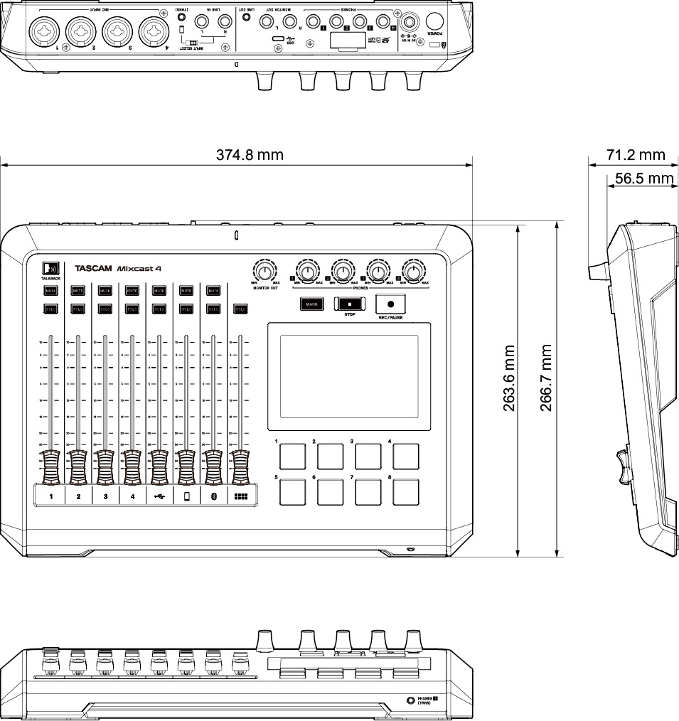
Block diagram
0324.MA-3230D


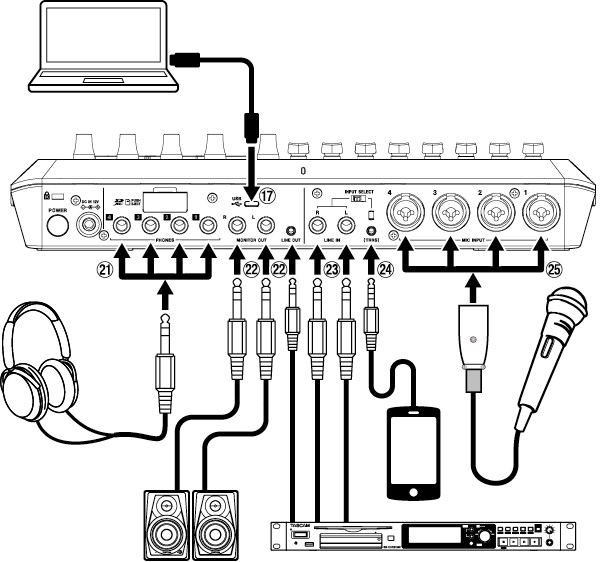
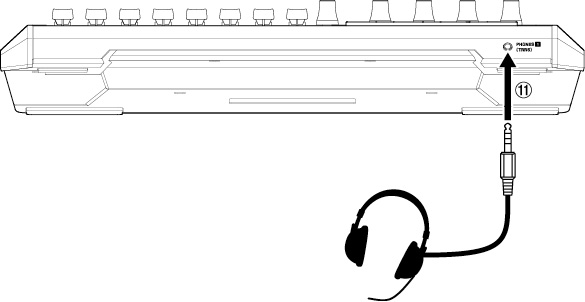
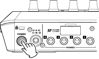
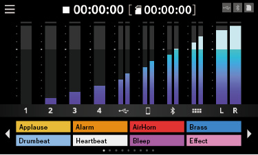
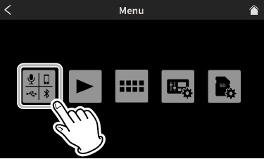
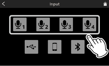
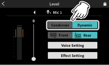
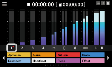
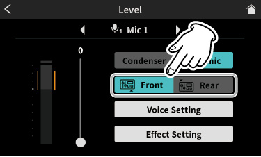
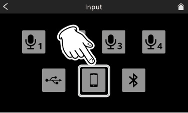
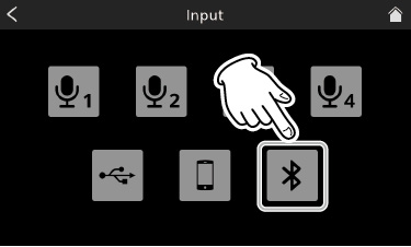
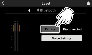
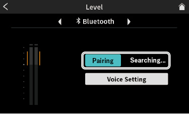


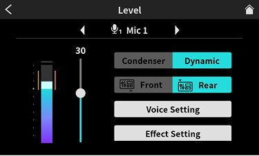
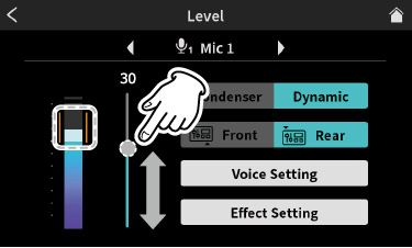
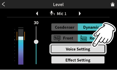
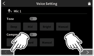
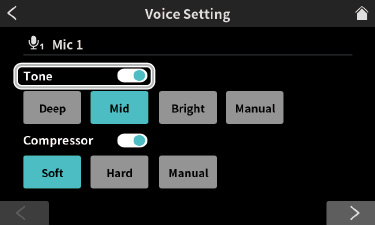


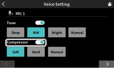


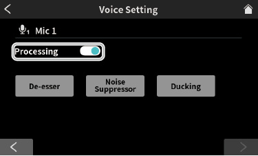
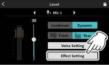
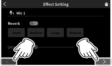
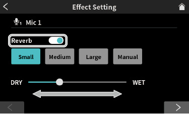


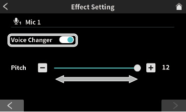
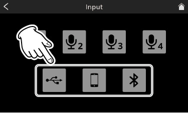
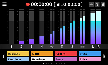

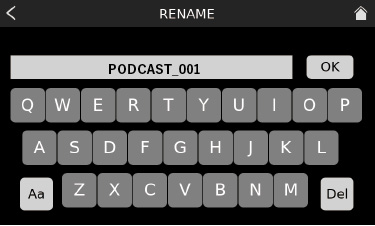
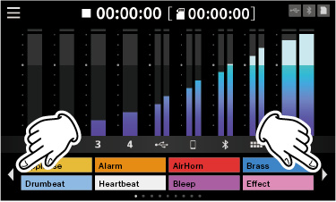
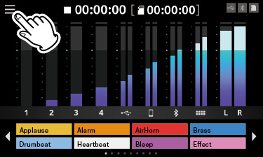
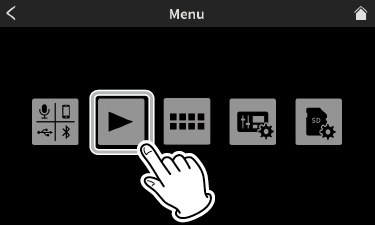
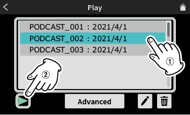
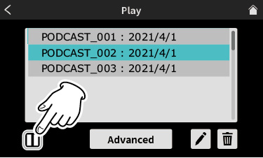
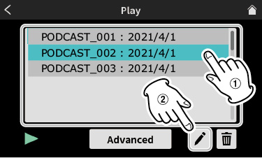
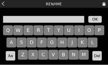
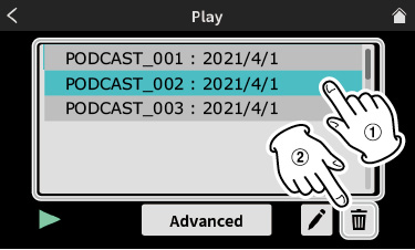


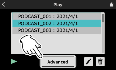
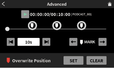
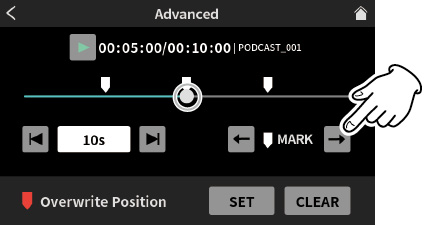
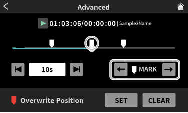
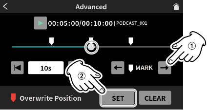
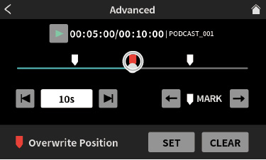
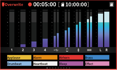

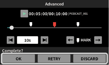

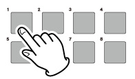
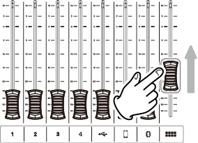
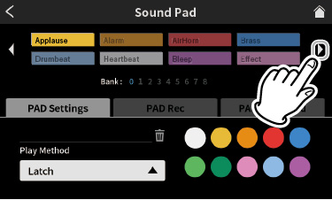
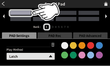
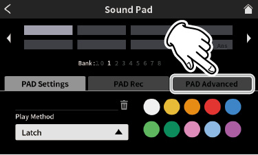
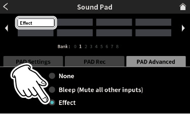
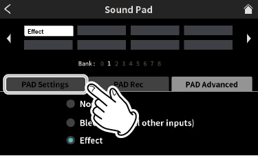
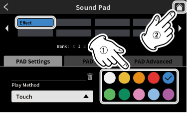
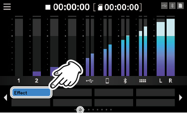

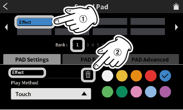

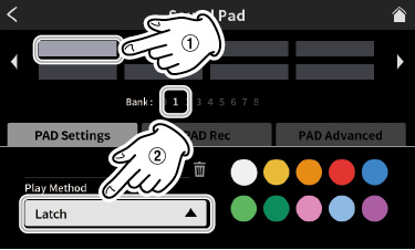

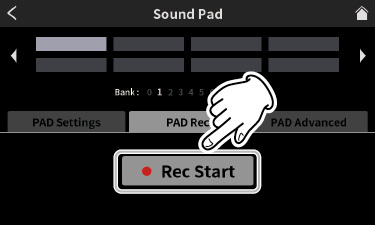
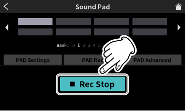
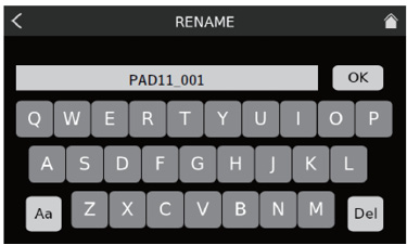
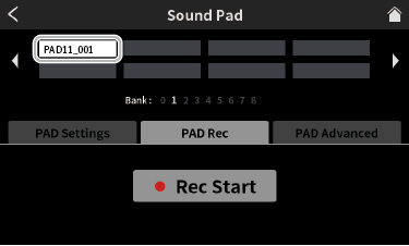
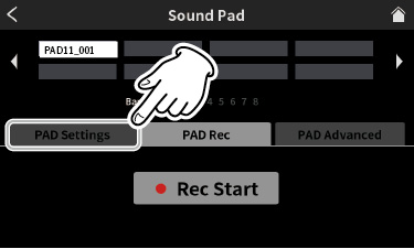
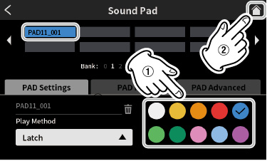
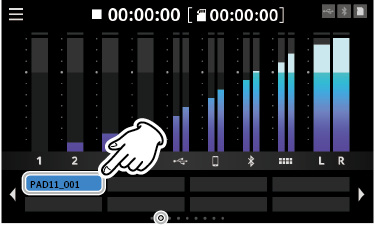

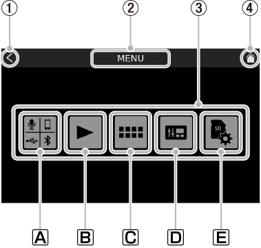
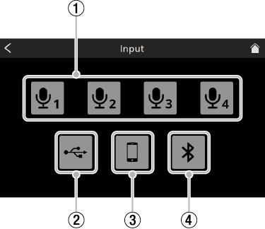
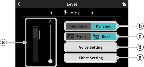
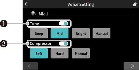
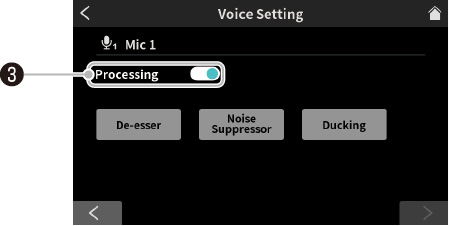


 settings icon disappear.


 setting icon disappear.

 setting icon disappear.

 setting icon disappear.
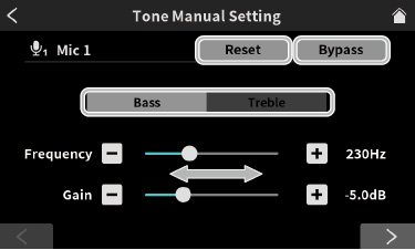
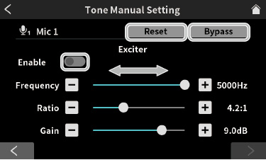
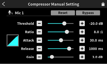
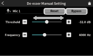
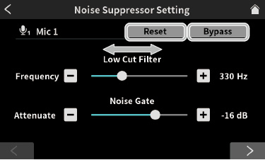

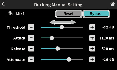
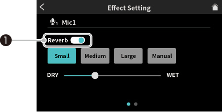
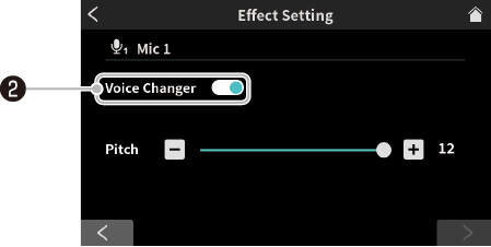


 settings icon disappear.
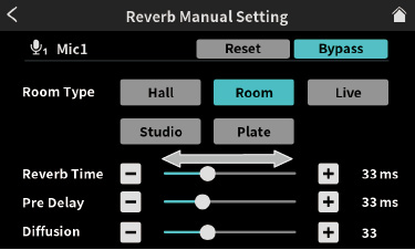
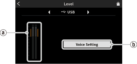
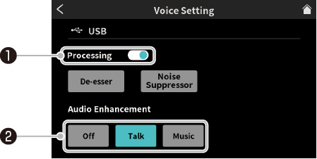


 setting icon disappear.

 setting icon disappear.
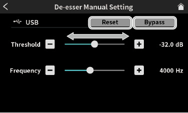
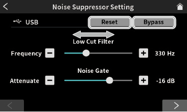
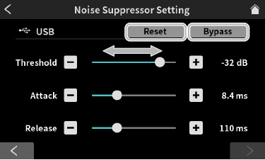
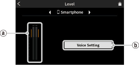
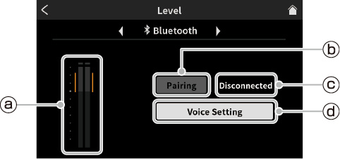
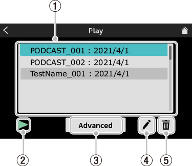
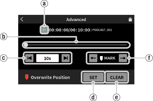
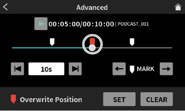
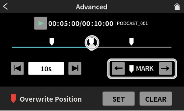

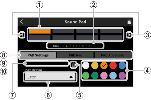
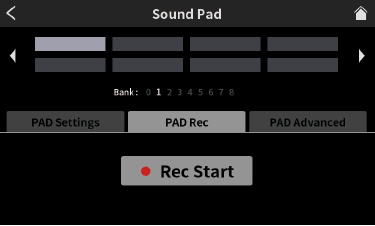
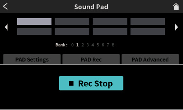
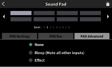
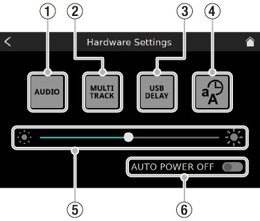
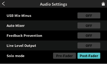
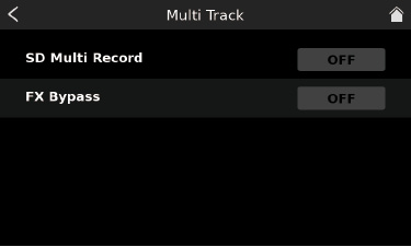
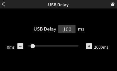
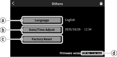
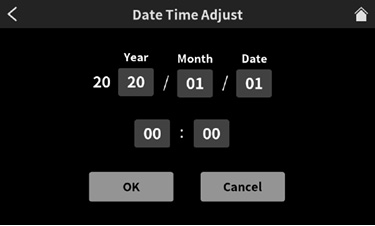
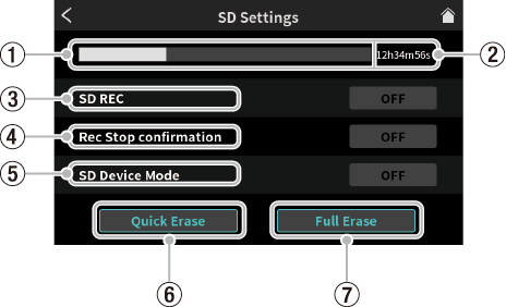
 output splits from PHONES
  output.